Table of Contents
Advertisement
Quick Links
USE AND MAINTENANCE MANUAL
TRANSLATION OF THE ORIGINAL INSTRUCTIONS – ENGLISH
INVERTER
GE 2000 MI
• Gruppo Elettrogeno
• Stromerzeuger
• Generating Set
• Grupo Gerador
• Groupe Electrogene
• Генераторная Установка
• Grupos Electrógenos
• Stroomaggregaten
M A D E
I N
• Skupina generátoru
I T A L Y
language
Codice
Code
Code
Codigo
CK8000119003
Kodezahl
Código
Код
Code
Edizione
Edition
Édition
Edición
04.2020
Ausgabe
Edição
Издание
Editie
Advertisement
Table of Contents

Subscribe to Our Youtube Channel
Related Manuals for Mosa GE 2000 MI


Summary of Contents for Mosa GE 2000 MI
- Page 1 USE AND MAINTENANCE MANUAL TRANSLATION OF THE ORIGINAL INSTRUCTIONS – ENGLISH Codice INVERTER Code Code Codigo CK8000119003 Kodezahl GE 2000 MI Código Код Code Edizione Edition Édition • Gruppo Elettrogeno • Stromerzeuger • Skupina generátoru Edición 04.2020 • Generating Set •...
- Page 3 Thank you for choosing a silent inverter gasoline engine generator set of our company. This manual contains the information on how to do that. Please read it carefully before operating. Operating safely and correctly can help you get the best results. All information in this publication is based on the latest product information available at the time of printing.
-
Page 4: Safety Warnings
SAFETY WARNINGS Personal safety and property safety of you and others are very important. . Please read these messages which is preceded by a symbol carefully. NOTICE DANGER You WILL be KILLED or SERIOUSLY HURT if you don’t follow instructions. WARNING You CAN be KILLED or SERIOUSLY HURT if you don’t follow instructions. -
Page 5: Table Of Contents
CONTENTS SAFETY WARNINGS ............... 2 SAFETY INFORMATION............5 LOCATION OF LABELS ............9 DESCRIPTION ................10 Electrical components............11 CONTROL FUNCTION............12 3 in 1 switch knob..............12 Oil warning light (red) ............12 Overload indicator light (Red)..........13 AC pilot light (Green). - Page 6 MAINTENANCE ..............27 Spark plug inspection............29 Carburetor adjustment............30 Engine oil replacement............30 Air filter ................31 Muffler screen and spark arrester ........32 Fuel tank filter ..............33 Fuel filter ................33 STORAGE................34 Drain the fuel..............34 Engine.
-
Page 7: Safety Information
1. SAFETY INFORMATION Read and understand this owner’s manual before operating your generator. It will help you avoid accidents if you get familiar with your generators safe operation procedures. Never use it indoors Never use it in a wet condition Never directly connect it to a home power system... - Page 8 Keep at least 1 meter away from Never smoke when refueling flammable substances Don’t spill when fueling Stop the engine before refueling...
- Page 9 Connections to a Home Power Supply NOTICE If the generator is to be connected to a home power supply as a standby, connection shall be performed by a professional electrician or by another person with proficient electrical skill. When the loads are connected to the generator, please carefully check whether electrical connections are safe and reliable.
- Page 10 System ground The generator has a system ground that connects the generator frame components to the ground terminals on the AC output receptacles. The generator neutral is floating, which means that the AC stator winding is isolated from the grounding fastener and the AC receptacle ground pins.
-
Page 11: Location Of Labels
LOCATION OF LABELS Please read the following labels before starting the generator. TIP: Keep or replace safety labels as needed. -
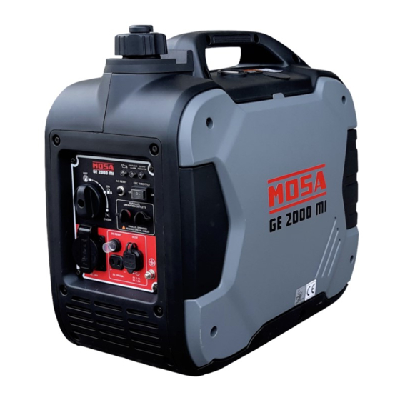
Page 12: Description
DESCRIPTION ① Carrying handle Tank cap breather knob ② ③ Fuel tank cap ④ Control panel ⑤ Recoil starter ⑥ Oil filler cap ⑦ Ventilation grille Muffler ⑧ Spark plug maintenance cover ⑨... -
Page 13: Electrical Components
3.1 Electrical components GE 2000 MI ① Oil warning light ② Indicator light ③ AC pilot light ④ ESC (Engine Smart Control) ⑤ 3 in 1 switch knob (including start/stop switch, fuel valve and choke) ⑥ AC receptacle ⑦ DC receptacle ⑧... -
Page 14: Control Function
4. CONTROL FUNCTION 4.1 3 in 1 switch knob ① Engine switch \fuel valve “OFF”; Ignition circuit is switched off. Fuel is switched off. The engine will not run. ② Engine switch \fuel valve \ chock “ON”; Ignition circuit is switched on. Fuel is switched on. Chock is switched on. The engine can be running. -
Page 15: Overload Indicator Light (Red)
4.3 Overload indicator light (Red) The overload indicator light ① comes on when an overload of a connected electrical device is detected, the inverter control unit overheats, or the AC output voltage rises. Then, the AC protector will trip, stopping power generation in order to protect the generator and any connected electric devices. -
Page 16: Dc Protector
4.5 DC protector The DC protector turns to “OFF” ② automatically when electric device being connected to the generator is operating and current above the rated flows. To use this equipment again, turn on DC protector by pressing its button to “ON” ① ①... -
Page 17: Fuel Tank Cap
Fuel tank cap Remove the fuel tank cap by turning it counterclockwise. Fuel tank cap air vent knob The fuel cap ② is equipped with a vent knob ① to stop the flow of petrol. The air vent knob must be turned to “ON”. This will al- low the fuel to flow to the carburetor and run the engine. -
Page 18: Preparation
5. PREPARATION 5.1 Fuel DANGER Fuel is highly flammable and poisonous. Check “SAFETY INFORMATION” • carefully before filling. Do not overfill the fuel tank, otherwise it may overflow when the fuel warms up • and expands. After fill the fuel, make sure the fuel tank cap •... -
Page 19: Engine Oil
5.2 Engine oil NOTICE The generator has been shipped without engine oil. Do not start the engine till fill with the sufficient engine oil. Place the generator on a level surface. Remove the screws ①, and then remove the cover ②. Remove the oil filler cap ③. -
Page 20: Pre-Operation Check
5.3 PRE-OPERATION CHECK WARNING If any item in the Pre-operation check is not working properly, have it inspected and repaired before operating the generator. The condition of a generator is the owner’s responsibility. Vital components can start to deteriorate quickly and unexpectedly, even if the generator unused. TIP: Pre-operation checks should be made each time the generator is used. -
Page 21: Operation
6. OPERATION WARNING Never operate the engine in a closed area or it may cause unconsciousness and • death within a short time. Operate the engine in a well ventilated area. Belare starting the engine, do not connect any electric devices •... -
Page 22: Starting The Engine
6.1 Starting the engine 1. Turn the ESC switch to “OFF” ①. Turn the knob of the cork of ventilation on “ON” ②. Turn the 3 in 1 switch to “CHOKE” ③ , Ignition circuit is switched on. Fuel is switched on. Hock is switched off. -
Page 23: Stopping The Engine
In ambient temperature below 0°C (32°F), the engine will run at the rated r/ • min (4500 r/min) for 5 minutes to warm up the engine. In ambient temperature below 5°C (41°F), the engine will run at the rated r/ •... -
Page 24: Alternating Current (Ac) Connection
6.3 Alternating Current (AC) connection WARNING Be sure any electric devices are turned off before plugging them in. NOTICE • Be sure all electric devices including the lines and plug connections are in good condition before connection to the generator. •... -
Page 25: Battery Charging
6.4 Battery Charging TIP: The generator DC rated voltage is 12V. • Start the engine first, and then connect the generator to the battery for • charging Before starting to charge the battery, make sure that the DC protector is •... - Page 26 Measure the specific gravity of electrolyte to determine if the battery is fully • charged. At full charge, the electrolyte specific gravity is between 1.26 and 1.28 lt is advisable to check the specific gravity of the electrolytic at least once every •...
-
Page 27: Application Range
6.5 Application range When using the generator, make sure the total load is within rated output of a ge- nerator. Otherwise, generator damage may occur. 0.4-0.75 0.8-0.95 Power fac- (Efficiency 0.85) Rated Rated voltage ≤1,800W ≤1,440W ≤544W output power TIP: Application wattage indicates when each device is used by itself. - Page 28 Do not overload. The total load of all electrical appliances appliance must nol • exceed the supply range of the generator. Overloading will damage the gene- rator. When supplying precision equipment, electronic controllers, PCs, Electronic • computers, microcomputer based equipment or battery chargers, keep the generator a sufficient distance away to prevent electrical interference from the engine.
-
Page 29: Maintenance
MAINTENANCE The engine must be properly maintained to ensure its operation be safe, economy and trouble-free, as well as eco-friendly. In order to keep your gasoline engine in good working condition, it must be perio- dically serviced. The following maintenance schedule and routine inspection pro- cedures must be carefully followed: Frequency First 1 month... - Page 30 NOTICE • If the gasoline engine frequently works under high temperature or heavy load, change the oil every 25 hours. • If the engine frequently work under dusty or other severe circumstances, clean the air filter element every 10 hours; If necessary, change the air filter element every 25 hours.
-
Page 31: Spark Plug Inspection
Spark plug inspection The spark plug is important engine components, which should be checked perio- dically. ① and use the tool ③ remove the spark plug cap ②, and Insert the tool ⑤ Remove the spark plug cap through the hol e from the outside of the cover. ④... -
Page 32: Carburetor Adjustment
7.2 Carburetor adjustment The carburetor is a vital part of the engine. Adjusting should be left to our com- pany authorized dealer with the professional knowledge, specialized date, and equipment to do so properly. 7.3 Engine oil replacement WARNING Avoid draining the engine oil immediately after stopping the engine. The oil is hot and should be handled with care to avoid burns. -
Page 33: Air Filter
Add engine oil to the upper level. Recommended engine oil: SAE SJ 15W-40 Recommended engine oil grade: API Service SE type or higher En- gine oil quantity: 0.35 L Wipe the cover clean, and wipe up any spilled oil. NOTICE Be sure no foreign material enters the crankcase. -
Page 34: Muffler Screen And Spark Arrester
The engine should never run without the foam element; excessive piston and cylinder wear may result. Install the air filter case cover in its original position and tighten the screw. Install the cover and tighten the screws. 7.5 Muffler screen and spark arrester WARNING The engine and muffler will be very hot after the engine has been run. -
Page 35: Fuel Tank Filter
Check the muffler screen and spark arrester. Replace them if damaged. Install the spark arrester. Align the spark arrester projection ⑦ TIP: with the hole ⑧ in the muffler pipe. Install the muffler screen and the muffler cap. Install the cover and tighten the screws. 7.6 Fuel tank filter WARNING Never use the gasoline while smoking or in the... -
Page 36: Storage
Remove the fuel filter ⑥. Clean the fuel filter with gasolinwe. Dry the filter and put it back in its original position. Install the fuel line and clamp, then open the fuel valve to check for leaks. Install the cover and tighten the screws. STORAGE Long term storage of your machine will require some preventive procedures to guard against deterioration. -
Page 37: Engine
Start the engine (See Page 20) and leave it run until it stops. The engine stops in approx. 20 minutes. Time by running out of fuel. TIP: Do not connect with any electrical devices. (unloaded operation) • Duration of the running engine depends on the amount of the fuel left in the •... -
Page 38: Troubleshooting
TROUBLESHOOTING Engine won’t start 1. Fuel systems No fuel supplied to combustion chamber. No fuel in tank ... Supply fuel. ○ Fuel in tank…. Fuel tank cap air vent knob and fuel tap knob to “ON” ○ Clogged fuel filter ..Clean fuel filter. ○... -
Page 39: Specifications
10. SPECIFICATIONS Item 2kW Generator Type Silent Inverter Rated frequency (Hz) 50/60 Rated voltage (V) 110/120/220/230/240 Rated output power (kW) Maximum output power (kW) Power factor ISO8528 G2 Generator Charging Voltage (DC) (V) Charging Current (DC) (A) Overload Protect (DC) Non-fuse Protector According to the directive 2000/14/EC and 2005/88/ECw Acoustic power: 90dBA Acoustic pressure level: 68dBA Tolerance K:2dBA Engine... -
Page 40: Wiring Diagram
WIRING DIAGRAM... - Page 44 MOSA div. della BCS S.p.A. Viale Europa, 59 20090 Cusago (Milano) Italy Tel.+39 - 0290352.1 Fax +39 - 0290390466 www.mosa.it...
Need help?
Do you have a question about the GE 2000 MI and is the answer not in the manual?
Questions and answers