Page 1
language USE AND MAINTENANCE MANUAL TRANSLATION OF THE ORIGINAL INSTRUCTIONS – ENGLISH
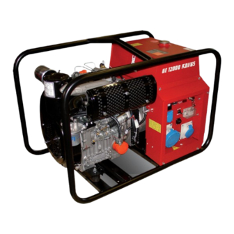
 Codice GE 12000 KDI - GS Code Code GE 14000 KD GS 159219003 Codigo Kodezahl Código Код Edizione Edition Édition • Gruppo Elettrogeno • Stromerzeuger Edición 03.2014 • Generating Set • Grupo Gerador Ausgabe • Groupe Electrogene...
DESCRIPTION OF THE MACHINE GE 12000 KDI/GS GE 14000 KD/GS REV.0-03/14 The generating set is a unit which transforms the mechanical energy, generated by endothermic engine, into electric energy, through an alternator. The assembling is made on a steel structure, on which are provided elastic support which must damp the vibrations and also eliminate sounds which would produce noise.
Page 4
INDEX GE 12000 KDI/GS GE 14000 KD/GS REV.0-03/14 M 1.01 COPYRIGHT M 1.1 NOTES M 1.4 CE MARK M 1.5 TECHNICAL DATA ADVICE M 2.1 SYMBOLS AND SAFETY PRECAUTIONS M 2.6 INSTALLATION AND ADVICE M 2.7 INSTALLATION AND DIMENSIONS UNPACKING M 4.1 TRANSPORT AND DISPLACEMENTS M 6.14...
Page 5
(see page M1.1). All rights are reserved to said Company. It is a property logo of MOSA division of B.C.S. S.p.A. All other possible logos contained in the documen- tation are registered by the respective owners.
Notes REV.0-10/02 INFORMATION INFORMATION OF GENERAL TYPE In the envelope given together with the machine and/or Dear Customer, set you will find: the manual for Use Maintenance and We wish to thank you for having bought a high quality set. Spare Parts, the manual for use of the engine and the tools (if included in the equipment), the guarantee (in the Our sections for Technical Service and Spare Parts will...
Page 7
CE MARK REV.7-02/14 Any of our product is labelled with CE marking attesting its conformity to appliable directives and also the fulfillment of safety requirements of the product itself; the list of these directives is part of the declaration of conformity included in any machine standard equipment. Here below the adopted symbol: CE marking is clearly readable and unerasable and it can be either part of the data-plate.
Page 8
Technical data and machine description GE 12000 KDI/GS GE 14000 KD/GS REV.0-03/14 Technical data GE 12000 KDI/GS GE 14000 KD/GS GENERATOR *Stand-by three-phase power 15 kVA (12 kW) / 400 V / 21.7 A *PRP three-phase power 13.5 kVA (10.8 kW) / 400 V / 19.5 A *Stand-by single-phase power 13.5 kVA (12.1 kW) / 230 V / 58.7 A *PRP single-phase power 12 kVA (10.8 kW) / 230 V / 52.5 A 5 kVA / 230 V / 21.7 A Frequecy 50 Hz 50 Hz Cos ϕ...
Page 9
WARNINGS REV.1-02/14 The installation and general warnings regarding operations are aimed achieving correct use of the machine and/or apparatus in the place where it is used as a genset and/or motor welder. - Advice to the User about the safety: + NB: The information contained in the manual can be changed without notice.
SYMBOLS AND SAFETY PRECAUTIONS REV.2-06/10 SYMBOLS PROHIBITIONS No harm for persons Use only with safety clothing - STOP - Read absolutely and be duly attentive It is compulsory to use the personal protection means given in equip- ment. Use only with safety clothing - Read and pay due attention It is compulsory to use the personal protection means given in equipment.
INSTALLATION AND ADVICE REV.1-06/07 Check that the air gets changed completely and the hot INSTALLATION AND ADVICE BEFORE USE air sent out does not come back inside the set so as to cause a dangerous increase of the temperature. GASOLINE ENGINES Use in open space, air swept or vent exhaust gases, which contain the deathly carbone oxyde, far from the work area.
Page 12
Installazione e dimensioni Luftzirkulation und abmessungen Installation and dimensions Instalación y dimensiones GE 12000 KDI/GS Installation et dimensions GE 14000 KD/GS REV.0-03/14 M1.4 1005 1430...
Page 13
UNPACKING REV.1-02/04 NOTE + Be sure that the lifting devices are: correctly mounted, adequate for the weight of the machine with it’s pack- aging, and conforms to local rules and regulations. When receiving the goods make sure that the product has not suffered damage during the transport, that there has not been rough handling or taking away of parts contained inside the packing or in the set.
Page 14
TRANSPORT AND DISPLACEMENTS COVERED UNITS REV.2-09/11 NOTE Transportation must always take place with the engine off, electrical cables and starting battery disconnected and fuel tank empty. Be sure that the lifting devices are: correctly mounted, adequate for the weight of the machine with it’s packaging, and conform to local rules and regulations.
Page 15
ASSEMBLY CTM 14 6.14 REV.0-03/09 Note: Lift the machine and assemble the parts as shown in the drawing ATTENTION The CTM accessory cannot be removed from the machine and used separately (actioned manually or following vehicles) for the transport of loads or anyway for used different from the machine mo- vements.
Set-up for operation (Engine diesel) Air cooled systems REV.2-03/15 BATTERY WITHOUT MAINTENANCE OIL BATH AIR FILTER The starter battery is supplied alre- Fill the air filter using the same engine oil up to the ady charged and ready for use. level indicated on the filter.
Page 17
Start-up GE 12000 KDI/GS GE 14000 KD/GS REV.0-03/14 REMOTE START (Only EAS version) Check daily The unit can also be started by means of the remote TCM control device, or through the EAS automatic NOTE intervention panel. Do not alter the primary conditions of regulation 1.
Stopping the engine GE 12000 KDI/GS GE 14000 KD/GS REV.0-03/14 SHUT-DOWN FROM FRONT PANEL EMERGENCY SHUTDOWN For shutdown under normal conditions, proceed as To shut down the engine in an emergency situation follows: turn the key (Q1) to the OFF position. 1.
Page 19
Comandi Controls GE 12000 KDI/GS Commandes GE 14000 KD/GS REV.0-03/14 N M N1 Description Description Referenzliste Pos. Descrizione Presa di messa a terra Earth terminal Prise de mise à terre Erdanschluss Presa di corrente in c.a. A.C. socket Prises de courant en c.a. Steckdose AC Filtro aria motore Engine air filter Filtre air moteur Luftfilter Motor Asta livello olio motore Oil level dipstick Jauge niveau huile moteur Ölmess-Stab Tappo caricamento olio motore Engine oil reservoir cap Bouchon remplissage huile moteur Füllverschluss Motoröl Tappo serbatoio Fuel tank cap Bouchon réservoir Füllverschluss Kraftstofftank Silenziatore di scarico...
Page 20
Using the generator REV.3-11/11 are the same. WARNING + In the absence of a load, the values for voltage and frequency can be greater than their nominal values. See It is absolutely forbidden to connect the unit sections on VOLTAGE and FREQUENCY. to the public mains and/or another electrical power source .
Page 21
Using the generator REV.1-09/05 The frequency, and therefore the number of motor SINGLE-PHASE LOADS revolutions, is maintained constant by the motor’s speed Power to monophase utilities by means of three-phase regulation system. generators requires some operating limitations. Generally, this regulator is of a mechanical type and - In single-phase operation, the declared voltage presents a droop from no-load to nominal load which tolerance can no longer be maintained by the regulator...
Page 22
Using the generator REV.1-09/05 DIFFERENTIAL SWITCH USAGE WITH EAS AUTOMATIC START-UP PANEL The differential switch or differential relay guarantee The electricity-generating group in combination with the protection against indirect contacts due to malfunction EAS automatic start-up panel forms a unit for distributing currents towards the ground.
Page 23
ACCESSORY USE REMOTE CONTROL 38.5 TCM 15 - 6 REV.1-07/11 MAKE SURE When the TCM 15 - 6 is used, it is not possible to connect the E.A.S automatic intervention unit. USE OF THE REMOTE CONTROL TCM 15 The coupling of the TCM 15 with the generating set, TCM 15 permits to work far from the set itself.
Page 24
GE 10000-12000 KD/GS-D Engine protection GE 12000 KDI/GS 39.6 GE 14000 KD/GS REV.0-03/14 The engine is equipped with system which shut- downs the engine in the event of low oil pressure and hight temperature. Low oil pressure and hight temperature are also indicated by the red warning lamp fitted on the control panel.
TROUBLE-SHOOTING GE 12000 KDI/GS 40.2 GE 14000 KD/GS REV.0-03/14 WARNING ● Have qualified personnel do maintenance and troubleshooting work. ● Stop the engine before doing any work inside the machine. If for any reason the machine must be operated while working inside, pay attention moving parts, hot parts (exhaust manifold and muffler, etc.) electrical parts which may be unprotected when the machine is open. ● Remove guards only when necessary to perform maintenance, and replace them when the maintenance requiring their removal is com- plete. ● Use suitable tools and clothes ● Do not modify the components if not authorized. - See pag. M1.1 - Problem Possible cause Solution ENGINE The engine does not start up, 1) Lack of fuel in tank or fuel tap closed 1) Refill the tank. Open the fuel tap or starts up and then stops im- 2) Fuel filter clogged 2) Replace mediately...
Page 26
MAINTENANCE REV.1-01/13 WARNING ● Have qualified personnel do maintenance and troubleshooting work. ● Stop the engine before doing any work inside the machine. If for any reason the machine must be operated while working inside, pay at- tention moving parts, hot parts (exhaust manifold and muffler, etc.) electrical parts which may be unprotected when the machine is open.
43.1 MAINTENANCE REV.0-09/05 ATTENTION Maintenance operations on the electricity-generating group prearranged for automatic operation must be carried out with the panel in RESET mode. Maintenance operations on the installation’s electrical panels must be carried out in complete safety by cutting off all external power sources: ELECTRICAL POWER, GROUP and BATTERY.
STORAGE REV.0-06/07 In case the machine should not be used for more than 30 days, make sure that the room in which it is stored presents a suitable shelter from heat sources, weather changes or anything which can cause rust, corrosion or damages to the machine.
Page 29
CUST OFF REV.0-06/07 Have qualified personnel disassemble the In case of necessity for first aid and fire prevention, machine and dispose of the parts, including the see page M2.5. oil, fuel, etc., in a correct manner when it is to be taken out of service.
Page 30
ELECTRICAL SYSTEM LEGENDE REV.10-05/13 A : Alternator E3 : Open circuit voltage switch I6 : Start Local/Remote selector N9 : UP/DOWN button mast B : Wire connection unit F3 : Stop push-button L6 : Choke button O9 : Hydraulic unit solenoid valve C : Capacitor G3 : Ignition coil M6 : Switch CC/CV P9 : Hydraulic unit engine D : G.F.I. H3 : Spark plug N6 : Connector – wire feeder Q9 : Ignitor E : Welding PCB transformer I3 : Range switch O6 : 420V/110V 3-phase transformer...
Page 32
Schema elettrico Electric diagram GE 12000 KDI/GS 61.1 Schemas electriques GE 14000 KD/GS REV.0-03/14 1N4007/1A...
Page 33
Schema elettrico Electric diagram GE 14000 KD/GS 61.2 Schemas electriques REV.0-03/14...
Page 34
Schema elettrico Electric diagram GE 12000 KDI/GS 61.3 Schemas electriques REV.0-03/14...
Need help?
Do you have a question about the GE 12000 KDI GS and is the answer not in the manual?
Questions and answers