Table of Contents
Advertisement
Available languages
Available languages
Quick Links
USE AND MAINTENANCE MANUAL
TRANSLATION OF THE ORIGINAL INSTRUCTIONS – ENGLISH
OPEN FRAME
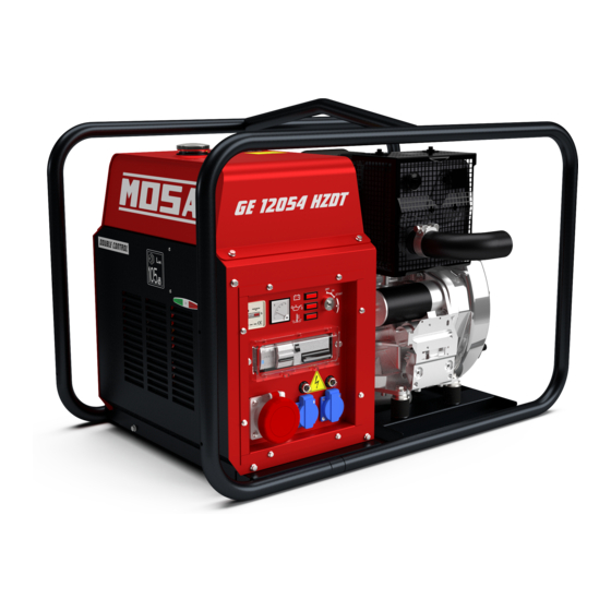
GE 12054 HZDT (STAGE V)
• Gruppo Elettrogeno
• Stromerzeuger
• Generating Set
• Grupo Gerador
• Groupe Electrogene
• Генераторная Установка
• Grupos Electrógenos
• Stroomaggregaten
M A D E
I N
• Skupina generátoru
I T A L Y
language
Codice
Code
Code
Codigo
Kodezahl
CD5R90139003
Código
Код
Code
Kód
Edizione
Edition
Édition
Edición
Ausgabe
03.2020
Edição
Издание
Editie
Edice
Advertisement
Table of Contents

Related Manuals for Mosa GE 12054 HZDT


Summary of Contents for Mosa GE 12054 HZDT
- Page 1 USE AND MAINTENANCE MANUAL TRANSLATION OF THE ORIGINAL INSTRUCTIONS – ENGLISH Codice OPEN FRAME Code Code Codigo GE 12054 HZDT (STAGE V) Kodezahl CD5R90139003 Código Код Code Kód Edizione Edition Édition • Gruppo Elettrogeno • Stromerzeuger • Skupina generátoru Edición...
-
Page 3: Table Of Contents
INDEX 0. GENERAL INFORMATION M1.1 INTRODUCTION ........................PAG. 4 CE MARK ..........................PAG. 5 M1.4 SYMBOLS AND SAFETY PRECAUTIONS ................... PAG. 6 WARNINGS ..........................PAG. 7 M2.1 M2.5... SAFETY RULES ........................PAG. 8 1. GENERAL INFORMATION OF THE MACHINE DESCRIPTION OF THE MACHINE ....................PAG. 10 DATA RECORDING ........................ -
Page 4: Introduction
INTRODUCTION Dear Customer, The Manufacturer shall not be liable for ANY USE OF THE PRO- We wish to thank you for having bought a high quality set. DUCT OTHER THAN THAT PRECISELY SPECIFIED IN THIS Our sections for Technical Service and Spare Parts will work at MANUAL and is thus not liable for any risks which may occur as best to help you if it were necessary. -
Page 5: Ce Mark
CE MARKING GENERATING SETS Any of our product is labelled with CE marking attesting its conformity to appliable directives and also the fulfillment of safety requirements of the product itself; the list of these directives is part of the declaration of conformity included in any machine standard equipment. -
Page 6: Symbols And Safety Precautions
SYMBOLS AND SAFETY PRECAUTIONS SYMBOLS IN THIS MANUAL DANGER - The symbols used in this manual are designed to call your GENERAL ADVICE - If the advice is not respec- attention to important aspects of the operation of the machine ted damage can happen to persons or things. -
Page 7: Warnings
WARNINGS FIRST AID. In case the operator shold be sprayed by accident, from corrosive liquids a/o hot toxic gas or whate- ver event which may cause serious injuries or death, predispose the first aid in accordance with the ruling labour accident standards or of local instructions. -
Page 8: M2.5
NORME DI SICUREZZA GRUPPI ELETTROGENI - TORRI FARO PRESCRIZIONI GENERALI DI SICUREZZA • Non trainare il carrello se i dispositivi di aggancio sono usu- + N.B.: le informazioni contenute nel manuale possono es- rati o danneggiati. sere variate senza preavviso. •... - Page 9 NORME DI SICUREZZA GRUPPI ELETTROGENI - TORRI FARO 2.5.1 PRESCRIZIONI DI SICUREZZA DURANTE LA MANUTEN- PRESCRIZIONI AGGIUNTIVE PER TORRI FARO ZIONE ATTENZIONE • Avvalersi di personale qualificato per effettuare la manuten- zione ed il lavoro di ricerca dei guasti. • E’ obbligatorio fermare il motore prima di effettuare qualsiasi La torre faro è...
-
Page 10: Description Of The Machine
DESCRIPTION OF THE MACHINE The generating set is a unit which transforms the mechanical energy, generated by endothermic engine, into electric energy, through an alternator. The assembling is made on a steel structure, on which are provided elastic support which must damp the vibrations and also eliminate sounds which would produce noise. -
Page 11: Data Recording
RECORDING DATA The manual is for the range of machines indicated on the front cover. With the scope to facilitate the search of the spare parts and maintain information of the bought machine, is necessary to record some data. Please write the requested data inside the squares to side: Model of machine Serial number of the machine Serial number of the engine... -
Page 12: Machine Unpacking
MACHINE UNPACKING NOTE Be sure that the lifting devices are: correctly mounted, adequate for the weight of the machine with it’s packaging, and conforms to local rules and regulations. When receiving the goods make sure that the product has not suffered damage during the transport, that there has not been rough handling or taking away of parts contained inside the packing or in the set. -
Page 13: Transport And Handling Covered Units
TRANSPORT AND HANDLING COVERED UNITS ATTENTION Transportation must always take place with the engine off, electrical cables and starting battery disconnected and fuel tank empty. Be sure that the lifting devices are: correctly mounted, adequate for the weight of the machine with it’s packaging, and conform to local rules and regulations. -
Page 14: Installation
INSTALLAZIONE - INSTALLATION - INSTALLATION INSTALACIÓN - LUFTZIRKULATION - INSTALAÇÃO УСТАНОВКА - INSTALLATIE M1.4 M1.4... -
Page 15: M2.6
InstallatIon advIces environMental conditions General installation criteria Installation of a genset has to be planned by qualified and trained technicians, it has to be carried out by a competent attention organization with qualified personnel and proper equipment. attention Open gensets (SKID) have to be located in an area pro- tected from rain, snow, high humidity and direct exposure to the sun. - Page 16 In order to avoid potentially dangerous situations, area surrounding genset should be isolated so that unauthorized people will not be able to get close to the unit. Even if MOSA Engine and alternator when in operation produce heat: gensets are manufactured according to electromagnetic •...
- Page 17 InstallatIon advIces 2.6.2 Sample of outdoor installation with shelter Floor should be levelled and suitable to sustain genset weight. Thresholds on doors and openings should have a barrier in or- der to avoid liquids leaking. In case it is not possible to provide a door with a barrier, the genset should have a collection base appropriate for the quantity of liquid it contains, in any case dimensions of collection base must be in accordance to the...
- Page 18 InstallatIon advIces 2.6.3 For open gensets installed indoors, we recommend: Electro ventilator capacity can be calculated as follows: • The dimensions of the air outlets be such that they have at least the same area of the radiator; Transmitted heat [Kcal/h] •...
-
Page 19: Set-Up For Operation Diesel Engine
SET-UP FOR OPERATION (DIESEL ENGINE) AIR COOLED SYSTEMS BATTERY WITHOUT MAINTENANCE (WHERE IT IS ASSEMBLED) FUEL The supplied battery is generally ready for use. ATTENTION Connect the cable + (positive) to the pole + of the battery, by properly tightening the clamp. Stop engine when fueling. -
Page 20: Earthing
Earthing Earthing WithOUt grOUnD FaULt intErrUPtEr Earthing With isOmEtEr The protection against electric shock from contact indirect is Machines equipped with insulation resistance monitor allow intentionally not to connect the ground terminal PE (12) to an ensured by the “electrical separation” with equipotential bonding earthing system. -
Page 21: Starting And Stopping Diesel Engine
STARTING AND STOPPING (DIESEL ENGINE) STOPPING Check daily Under normal conditions, use the following procedure: 1) stop the power source, turning off the connected equipment, if they do not have a power switch, open the main switch of NOTE the machine (lever facing down) 2) allow the engine to run without any load for a few minutes Do not alter the primary conditions of regulation and do not touch the sealed parts. -
Page 22: Controls Legende
CONTROLS LEGENDE Hydraulic oil level light Engine control unit EP2 Engine control unit EP6 Welding socket ( + ) E.A.S. connector Welding voltage voltmeter Welding socket ( - ) Exclusion indicating light PTO HI Polarity inverter control Earth terminal Auxiliary current push button Oil pressure indicator A.C. - Page 23 COMANDI - CONTROLS - COMMANDES - MANDOS - BEDIENELEMENTE - COMANDOS СИСТЕМЫ УПРАВЛЕНИЯ - BEDIENING ISOMETER (1x400V - 2x230V) ISOMETER (2x400V - 1x230V) A3-U5-Z2 A3-U5-Z2 N2-Z2 DGVU-I203-032 (1x400V - 2x230V)
-
Page 24: Controls
CONTROLS DESCRIPTION Pos. Description Function Thermal-magnetic circuit breaker General switch for the gen-set. It protects both gen-set and related electrical circuit from over current / short circuit. Thermal-magnetic circuit breaker / 2x16A Curve C 2P - Id=0,03 (for 16A-230V socket) Ground fault interrupter Insulation monitoring Protection device against indirect contact for IT systems (GE neutral not to ground). -
Page 25: M37
Utilizzo del generatore CONDIZIONI OPERATIVE ATTENZIONE POTENZA La potenza elettrica espressa in kVA di un gruppo elettrogeno E’ assolutamente vietato collegare il gruppo alla rete pub- è la potenza disponibile in uscita alle condizioni ambientali di blica e/o comunque con un’altra fonte di energia elettrica. riferimento e ai valori nominali di: tensione, frequenza, fattore E' vietato l’accesso nell'area adiacente al gruppo di potenza (cos ϕ). - Page 26 Utilizzo del generatore 37.1 FREQUENZA In tutti i casi quando il circuito utilizzatore prevede l’avviamento La frequenza è un parametro direttamente dipendente dalla di un motore asincrono è necessario controllare che non vi velocità di rotazione del motore. In funzione del tipo di alterna- siano utenze inserite nell’impianto che a causa della caduta di tore 2 o 4 poli si avrà...
- Page 27 Utilizzo del generatore 37.2 UTILIZZO CON QUADRO D'AVVIAMENTO AU- In caso di intervento della protezione magnetotermica verificare che l’assorbimento totale non superi la corrente nominale del TOMATICO EAS gruppo elettrogeno. Il gruppo elettrogeno abbinato al quadro di avviamento auto- matico EAS forma un complesso per l’erogazione di energia INTERRUTTORE DIFFERENZIALE elettrica entro pochi secondi al mancare della Rete Elettrica L’interruttore differenziale o il relè...
-
Page 28: M39.10 Protezione Motore - Sorvegliatore D'isolamento
ENGINE PROTECTION INSULATION MONITORING 39.10 LEGEND: NOTE Adjustment of Alarm threshold Set-alarm dip-switches Led, pre-allarm indication DO NOT INTERVENE ON THE SETTING OF THE PROTEC- TION SWITCH. BEFORE USING THE MACHINE CHECK Led , power indication Led Alarm indication THE ON WARNING LAMP LIGHTING. Test push-button Reset push-button Adjustment of- PRE-ALARM threshold... -
Page 29: M40.2
RICERCA GUASTI 40.2 Problema Possibile causa Rimedio MOTORE Il motore non si avvia Selettore d'avviamento (I6) (ove montato) in posi- 1) Verificare posizione zione errata Pulsante d'emergenza (L5) premuto Sbloccare Preriscaldo (ove montato) 3) Mancata o insufficiente fase di preriscaldo cande- lette. Avaria nel circuito, riparare. Unità di controllo motore o chiave di avviamento Sostituire difettosi Batteria scarica... - Page 30 RICERCA GUASTI 40.2.1 GENERATORE Assenza di tensione in uscita 1) Intervento protezione per sovraccarico 1) Controllare il carico collegato e diminuire 2) Intervento protezione differenziale 2) Controllare l’isolamento dell’intero sistema: cablaggio, connessioni, carico collegato e verificare che non ci siano perdite d’isolamento che causino correnti di guasto a terra. 3) Protezioni difettose 3) Sostituire 4) Alternatore non eccitato 4) Effettuare la prova di eccitazione esterna come indicato nel manuale specifico dell’alternatore.
-
Page 31: M43
MANUTENZIONE ATTENZIONE Avvalersi di personale qualificato per effettuare la manutenzione ed il lavoro di ricerca dei guasti. E’ obbligatorio fermare il motore prima di effettuare qualunque manu- tenzione alla macchina. A macchina in funzione prestare attenzione a: - Parti rotanti - Parti calde (collettori e silenziatori di scarico, turbine, e/o altro) - Parti in tensione. - Page 32 MANUTENZIONE 43.1 ATTENZIONE • Tutte le operazioni di manutenzione sul gruppo elettrogeno predisposto per l'intervento automatico devono essere effettuate con il quadro in modalità RESET. • Le operazioni di manutenzione sui quadri elettrici dell'impianto devono essere effettuate in completa sicurezza sezionando tutte le fonti di alimentazione esterna: RETE, GRUPPO e BATTERIA.
-
Page 33: M45 Storage And Disassemble
RIMESSAGGIO E DISMISSIONE RIMESSAGGIO DISMISSIONE Avvalersi di personale qualificato per effettuare le oper- Nel caso in cui la macchina non fosse utilizzata per un periodo azioni necessarie alla dismissione. superiore ai 30 giorni, accertarsi che l’ambiente in cui è rimes- sa assicuri un adeguato riparo da fonti di calore, mutamenti meteorologici od ogni quant’altro possa provocare ruggine, Per dismissione s’intendono tutte le operazioni da effettuare,... -
Page 34: Technical Data
TECHNICAL DATA GENERATOR GE 12054 HZDT *Three-phase power Stand-by 12 kVA (9.6 kW) / 400 V / 17.3 A *Three-phase power PRP 11 kVA (8.8 kW) / 400 V / 15.9 A *Single-phase power Stand-by 6 kVA / 230 V / 26 A... - Page 35 DIMENSIONI - DIMENSIONS - DIMENSIONS - DIMENSIONES ABMESSUNGEN - DIMENSÕES - РАЗМЕРЫ - AFMETINGEN 2.7.1 1005 1430...
- Page 36 NOTE...
- Page 37 NOTE...
- Page 38 NOTE...
- Page 40 MOSA div. della BCS S.p.A. Viale Europa, 59 20090 Cusago (Milano) Italy Tel.+39 - 0290352.1 Fax +39 - 0290390466 www.mosa.it...
Need help?
Do you have a question about the GE 12054 HZDT and is the answer not in the manual?
Questions and answers