Advertisement
Overview
This quick start guide provides the basic information you
need to mount and install the FT-04A.
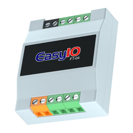
Figure 1: FT-04A front view
Callout
Description
1
Hot (H) and Ground (G) terminals
2
Analog output (AO) 1 and COM terminal
AO2 and COM terminal
3
Universal input (UI) 1 and COM terminal
UI2 and COM terminal
4
Undesignated terminal
FT-04A Quick Start Guide
FT-04A dimensions
See the following figure for the dimensions of the FT-04A.
Figure 2: FT-04A dimensions, mm (in.)
Parts included
•
Five FT-04A controllers
•
One pack sheet
Required tools and parts
One small flathead screwdriver to secure the wires to the
terminal blocks.
Mounting guidelines
Do not mount the controller in a location with any of the
environmental disturbances listed in
to
avoid.
Mounting locations to avoid
•
Areas with excessive moisture, corrosive fumes, or
explosive vapors
•
Locations where excessive vibration or shock occurs
•
Locations with excessive electrical noise, such as large
magnetic interference or variable speed drive modules
Optional mounting accessories
The EIO-FT-Clip is a mounting bracket that you can attach
to the bottom of the EasyIO FT-04 controller. See
for dimensions of the EIO-FT-Clip.
LIT-12014187 Version 1.0
2023-07-27
Mounting locations
Figure 3
EASYIO-FT-04A
Advertisement
Table of Contents

Related Manuals for Johnson Controls FT-04A


Summary of Contents for Johnson Controls FT-04A
- Page 1 LIT-12014187 Version 1.0 2023-07-27 Overview FT-04A dimensions See the following figure for the dimensions of the FT-04A. This quick start guide provides the basic information you need to mount and install the FT-04A. Figure 2: FT-04A dimensions, mm (in.) Figure 1: FT-04A front view Parts included •...
- Page 2 Detaching the FT Clip from any FT series controller Hold the FT-04A controller in one hand and the FT Clip in the other hand. Pull apart the FT-04A controller from the FT clip. FT-04A Quick Start Guide...
- Page 3 Important Use the correct electrostatic discharge precautions throughout installation, setup, and service to avoid damage to the controller and controller components. FT-04A basic input, output, power and serial device wiring setup WARNING Input, output, and 24 VAC Class 2 transformer power input wiring Class 2 devices wiring only –...
- Page 4 Figure 7: FT-04A wiring guide Figure 8: 24 VAC Class 2 transformer power input Callout Description 20 AWG copper stranded wire Controller H terminal G terminal Figure 9: Analog output wiring Callout Description Field device 22 AWG copper stranded twisted wire up to 100 m (328 ft) in length.
- Page 5 Normally open (NO) or normally closed (NC) as required Connecting to a controller with Wi-Fi On the desktop toolbar on your computer, click your Wi-Fi network icon. Find the controller's SSID, then connect to the controller. FT-04A Quick Start Guide...
- Page 6 FT LED states Table 2: FT LED states LED label LED color Normal state State Description Blue 1 Hz blinks 1 Hz blinks Normal operation Fast blink Controller in fault condition or controller in bootloader mode FT-04A Quick Start Guide...
-
Page 7: Troubleshooting
1 V. the command. Disconnect the connected device and verify the The Common Reference is commanded value is present. incorrect. Technical specifications Table 4: FT-04A UL input, output, and communication ratings Specification Description Terminal Power supply • 24 VAC, ± 5% H and G •... - Page 8 Table 5: FT-04A technical specifications Specification Description Controller processor and memory specifications Main processor ESP32 240Mhz Flash memory 16 MB 4 MB Product temperature and humidity specifications Operating temperature 0°C to 50°C (32°F to 122°F) Storage temperature -20°C to 65 °C (-4°F to 150°F)
- Page 9 Compliance Table 6: FT-04A Compliance North America: UL 916 Energy Management Equipment; FCC Class B, Part 15, Subpart C 15.247 This device contains licence-exempt transmitter(s)/receiver(s) that comply with Innovation, Science and Economic Development Canada’s licence-exempt RSS(s). This device complies with part 15 of the FCC Rules.
-
Page 10: Product Warranty
Contact your local Johnson Controls representative: www.johnsoncontrols.com/locations Contact Johnson Controls: www.johnsoncontrols.com/ contact-us © 2023 Johnson Controls. All rights reserved. All specifications and other information shown were current as of document revision and are subject to change without notice. www.johnsoncontrols.com...
Need help?
Do you have a question about the FT-04A and is the answer not in the manual?
Questions and answers