Table of Contents
Advertisement
Quick Links
FX-PCX3721 Expansion Input/Output Module Installation
Instructions
FX-PCX3721-0
Application
The FX-PCX3721 Expansion Input/Output (I/O) Module
is a part of the Facility Explorer FX-PC Series
Programmable Controller family. FX-PCXs expand the
number of points connected to an FX-PCA, FX-PCG, or
FX-PCV programmable controller or to a supervisory
controller to monitor and control a wide variety of HVAC
equipment.
FX-PCX controllers operate on an RS-485 BACnet®
Master-Slave/Token-Passing (MS/TP) Bus as BACnet
Application Specific Controllers (B-ASCs) and integrate
into Johnson Controls® and third-party BACnet systems.
Note: At FX-PCT Release 10.1, a new capability was
introduced allowing FX-PCVs, FX-PCGs, and
FX-PCAs to communicate by using either the
BACnet or the N2 field bus networking protocol.
The operation of the FX-PCX Input/Output Module
is not affected by the selection of the BACnet or
the N2 protocol in the host controller.
North American Emissions
Compliance
Canada
This Class (A) digital apparatus meets all the
requirements of the Canadian Interference-Causing
Equipment Regulations.
Cet appareil numérique de la Classe (A) respecte toutes
les exigences du Règlement sur le matériel brouilleur
du Canada.
United States
This equipment has been tested and found to comply
with the limits for a Class A digital device pursuant to
Part 15 of the FCC Rules. These limits are designed to
provide reasonable protection against harmful
interference when this equipment is operated in a
commercial environment. This equipment generates,
uses, and can radiate radio frequency energy and, if not
installed and used in accordance with the instruction
manual, may cause harmful interference to radio
communications. Operation of this equipment in a
residential area may cause harmful interference, in which
case the users will be required to correct the interference
at their own expense.
FX-PCX3721 Expansion Input/Output Module Installation Instructions
Part No. 24-10144-203, Rev. D
Refer to the
QuickLIT website
Installation
Observe these guidelines when installing the controller:
•
Transport the controller in the original container to
minimize vibration and shock damage.
•
Verify that all parts shipped with the controller.
•
Do not drop the controller or subject it to physical
shock.
Parts Included
•
one FX-PCX controller with removable terminal blocks
(Power, SA, and FC bus are removable)
•
one installation instructions sheet
Materials and Special Tools Needed
•
three fasteners appropriate for the mounting surface
(M4 screws or #8 screws)
•
one 20 cm (8 in.) or longer piece of 35 mm DIN rail
and appropriate hardware for DIN rail mount (only)
•
small straight-blade screwdriver for securing wires in
the terminal blocks
Mounting
Observe these guidelines when mounting an FX-PCX
controller:
•
Ensure the mounting surface can support the
controller, DIN rail, and any user-supplied enclosure.
•
Mount the controller horizontally on 35 mm DIN rail
whenever possible.
•
Mount the controller in the proper mounting position
(Figure
1).
•
Mount the controller on a hard, even surface
whenever possible in wall-mount applications.
•
Use shims or washers to mount the controller securely
and evenly on the mounting surface.
•
Mount the controller in an area free of corrosive
vapors and observe the Ambient Conditions
requirements in
Table
9.
•
Provide for sufficient space around the controller for
cable and wire connections for easy cover removal
and good ventilation through the controller (50 mm
Issued December 5, 2014
for the most up-to-date version of this document.
1
Advertisement
Table of Contents

Related Manuals for Johnson Controls FX-PCX3721


Summary of Contents for Johnson Controls FX-PCX3721
- Page 1 QuickLIT website for the most up-to-date version of this document. Application Installation The FX-PCX3721 Expansion Input/Output (I/O) Module is a part of the Facility Explorer FX-PC Series Observe these guidelines when installing the controller: Programmable Controller family. FX-PCXs expand the •...
-
Page 2: Wall Mount Applications
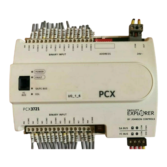
(DIN rail) channel on the back of the controller (Figure 2), and position the controller snugly against the DIN rail. 4. Push the bottom mounting clips inward (up) to secure the controller on the DIN rail. FX-PCX3721 Expansion Input/Output Module Installation Instructions... - Page 3 Figure 3: FX-PCX3721 Physical Features Table 1: FX-PCX3721 Feature Callout Numbers and Descriptions Callout Physical Feature: Description and References Device Address DIP Switch Block (See Setting the Device Addresses) 24 VAC, Class 2 Supply Power Terminal Blocks (See Supply Power Terminal...
-
Page 4: Terminal Blocks And Bus Ports
5. See Table MS/TP Bus, FC bus, and SA bus, refer to the FX-PC for more information. Series Controllers MS/TP Communications Bus Technical Bulletin (LIT-12011670) or MS/TP Communications Bus for BCM System Technical Bulletin (LIT-12011908). FX-PCX3721 Expansion Input/Output Module Installation Instructions... -
Page 5: Supply Power Terminal Block
The SA/FC bus port pin assignment is shown in Figure Note: The supply power wire colors may be different on transformers from other manufacturers. Refer to the transformer manufacturer’s instructions and the project installation drawings for wiring details. FX-PCX3721 Expansion Input/Output Module Installation Instructions... -
Page 6: Termination Details
Wireless Field Bus System Technical Bulletin (LIT-12011660). Termination Details A set of Johnson Controls termination diagrams provides details for wiring inputs and outputs to the controllers. See Table 2 in this section for the applicable termination diagram. Table 2: Termination Details... -
Page 7: Cable And Wire Length Guidelines
Table 3: FX-PCX3721 Terminal Blocks, Functions, Ratings, Requirements, and Cables Terminal Block Terminal Function, Ratings, Requirements Determine Wire Size and Label Label Maximum Cable Length BINARY INPUT IN n Binary Input - Dry Contact Maintained Mode See Guideline A in Table 4 0.01 second minimum pulse width Internal 18 V, 3k ohm... -
Page 8: Sa/Fc Bus And Supply Power Wiring Guidelines
Refer to the FX-PC Series Controllers MS/TP Communications Bus Technical Bulletin (LIT-12011670) or MS/TP Communications Bus for BCM System Technical Bulletin (LIT-12011908) for detailed information regarding wire size and cable length requirements for the SA and FC buses. FX-PCX3721 Expansion Input/Output Module Installation Instructions... -
Page 9: Setup And Adjustments
SA and FC bus applications. Set switch 128 to the controller on the bus. to ON for wireless FC bus applications only. To set the device addresses on FX-PCX controllers: FX-PCX3721 Expansion Input/Output Module Installation Instructions... -
Page 10: Removing The Controller Cover
MS/TP buses. inside of the housing cover. To remove the controller cover: 1. Place your fingernails under the two cover lift tabs (Figure 3) on the sides of the housing cover and FX-PCX3721 Expansion Input/Output Module Installation Instructions... -
Page 11: Setting The End-Of-Line (Eol) Switch
Off Steady = No Data Transmission (N/A - auto baud not supported) On Steady = Communication lost, waiting to join communication ring Amber Off (Except on On Steady = EOL switch in ON position terminating Off Steady = EOL switch in Off position devices) FX-PCX3721 Expansion Input/Output Module Installation Instructions... -
Page 12: Repair Information
Note: The ZFR-USBHA-0 replaces the IA OEM DAUBI_2400 ZigBee USB dongle. For additional information on the ZFR-USBHA-0 ZigBee dongle, refer to the FX-ZFR Series Wireless Field Bus System Technical Bulletin (LIT-12011660) or FX-ZFR Series Wireless Field Bus System Quick Reference Guide (LIT-12011696). FX-PCX3721 Expansion Input/Output Module Installation Instructions... -
Page 13: Technical Specifications
The performance specifications are nominal and conform to acceptable industry standard. For application at conditions beyond these specifications, consult the local Johnson Controls® office. Johnson Controls, Inc. shall not be liable for damages resulting from misapplication or misuse of its products. - Page 14 Building Efficiency 507 E. Michigan Street, Milwaukee, WI 53202 Johnson Controls® is a registered trademark of Johnson Controls, Inc. All other marks herein are the marks of their respective owners.© 2014 Johnson Controls, Inc. Published in U.S.A. www.johnsoncontrols.com FX-PCX3721 Expansion Input/Output Module Installation Instructions...
Need help?
Do you have a question about the FX-PCX3721 and is the answer not in the manual?
Questions and answers