Table of Contents
Advertisement
Quick Links
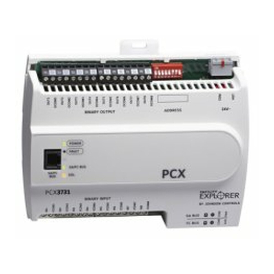
FX-PCX3731 Input/Output Module Installation Instructions
FX-PCX3731-0
Application
The FX-PCX3731 controller is a part of the Facility
Explorer FX-PC Series Programmable Controller family.
FX-PCX controllers expand the number of points
connected to an FX-PCA, FX-PCG, or FX-PCV
programmable controller or to an FX Supervisory
Controller.
FX-PCX controllers operate on an RS-485 BACnet®
Master-Slave/Token-Passing (MS/TP) Bus as BACnet
Application Specific Controllers (B-ASCs) and integrate
into the web-based Facility Explorer system.
Note: At FX-PCT Release 10.1, a new capability was
introduced allowing FX-PCVs, FX-PCGs, and
FX-PCAs to communicate by using either the
BACnet or the N2 field bus networking protocol.
The operation of the FX-PCX Input/Output Module
is not affected by the selection of the BACnet or
the N2 protocol in the host controller.
North American Emissions
Compliance
Canada
This Class (A) digital apparatus meets all the
requirements of the Canadian Interference-Causing
Equipment Regulations.
Cet appareil numérique de la Classe (A) respecte toutes
les exigences du Règlement sur le matériel brouilleur
du Canada.
United States
This equipment has been tested and found to comply with the
limits for a Class A digital device pursuant to Part 15 of the
FCC Rules. These limits are designed to provide reasonable
protection against harmful interference when this equipment
is operated in a commercial environment. This equipment
generates, uses, and can radiate radio frequency energy and,
if not installed and used in accordance with the instruction
manual, may cause harmful interference to radio
communications. Operation of this equipment in a residential
area may cause harmful interference, in which case the users
will be required to correct the interference at their own expense.
FX-PCX3731 Input/Output Module Installation Instructions
Part No. 24-10144-181, Rev. C
Refer to the
QuickLIT website
Installation
Observe these guidelines when installing a controller:
•
Transport the controller in the original container to
minimize vibration and shock damage.
•
Verify that all parts shipped with the controller.
•
Do not drop the controller or subject it to physical
shock.
Parts Included
•
one controller with removable terminal blocks (Power,
SA, and FC bus are removable)
•
one installation instructions sheet
Materials and Special Tools Needed
•
three fasteners appropriate for the mounting surface
(M4 screws or #8 screws)
•
one 20 cm (8 in.) or longer piece of 35 mm DIN rail
and appropriate hardware for DIN rail mount (only)
•
small straight-blade screwdriver for securing wires in
the terminal blocks
Mounting
Observe these guidelines when mounting an FX-PCX
controller:
•
Ensure the mounting surface can support the
controller, DIN rail, and any user-supplied enclosure.
•
Mount the controller horizontally on 35 mm DIN rail
whenever possible.
•
Mount the controller in the proper mounting position
(Figure
1).
•
Mount the controller on a hard, even surface
whenever possible in wall-mount applications.
•
Use shims or washers to mount the controller securely
and evenly on the mounting surface.
•
Mount the controller in an area free of corrosive
vapors and observe the Ambient Conditions
requirements in
Table
9.
•
Provide for sufficient space around the controller for
cable and wire connections for easy cover removal
and good ventilation through the controller (50 mm
[2 in.] minimum on the top, bottom, and front of the
controller).
Issued December 5, 2014
for the most up-to-date version of this document.
1
Advertisement
Table of Contents

Related Manuals for Johnson Controls FX-PCX3731


Summary of Contents for Johnson Controls FX-PCX3731
- Page 1 QuickLIT website for the most up-to-date version of this document. Application Installation The FX-PCX3731 controller is a part of the Facility Explorer FX-PC Series Programmable Controller family. Observe these guidelines when installing a controller: FX-PCX controllers expand the number of points •...
-
Page 2: Wall Mount Applications
(DIN rail) channel on the back of the controller (Figure 2), and position the controller snugly against the DIN rail. 4. Push the bottom mounting clip inward (up) to secure the controller on the DIN rail. FX-PCX3731 Input/Output Module Installation Instructions... - Page 3 Figure 3: FX-PCX3731 Physical Features Table 1: FX-PCX3731 Physical Features Callouts and Descriptions Callout Physical Feature: Description and References Binary Outputs (BOs) Terminal Block (See Table Mounting Clip (Three Total) Device Address DIP Switch Block (See Setting the Device Addresses)
-
Page 4: Terminal Blocks And Bus Ports
For detailed information on configuring and wiring an twisted, shielded cable as shown in Figure 5. See Table MS/TP Bus, FC bus, and SA bus, refer to the FX-PC for more information. Series Controllers MS/TP Communications Bus Technical Bulletin (LIT-12011670). FX-PCX3731 Input/Output Module Installation Instructions... -
Page 5: Supply Power Terminal Block
The SA/FC bus port pin assignment is shown in Figure Note: The supply power wire colors may be different on transformers from other manufacturers. Refer to the transformer manufacturer’s instructions and the project installation drawings for wiring details. FX-PCX3731 Input/Output Module Installation Instructions... -
Page 6: Wireless Network Applications
Field Bus Router Installation Instructions (Part No. 24-10325-29). Termination Details A set of Johnson Controls® termination diagrams provides details for wiring inputs and outputs to the controllers. See the figures in this section for the applicable termination diagrams. Table 2: Termination Details... -
Page 7: Terminal Wiring Guidelines, Functions, Ratings, And Requirements
Inputs/outputs with cables less than 30 m (100 ft) typically do not require an offset in the software setup. Cable runs over 30 m (100 ft) may require an offset in the input/output software setup. FX-PCX3731 Input/Output Module Installation Instructions... -
Page 8: Cable And Wire Length Guidelines
Table 3: FX-PCX3731 Terminal Blocks, Functions, Ratings, Requirements, and Cables Terminal Block Terminal Function, Ratings, Requirements Determine Wire Size and Label Label Maximum Cable Length BINARY INPUT IN n Binary Input - Dry Contact Maintained Mode See Guideline A in Table 4 0.01 second minimum pulse width Internal 18 V, 3k ohm... - Page 9 N/A (24 AWG) stranded copper 61 m (200 ft) twisted wire Figure 8 to select wire size/gauge. Figure 8 to determine Use stranded copper wire cable length. Use twisted wire cable. FX-PCX3731 Input/Output Module Installation Instructions...
-
Page 10: Maximum Cable Length Versus Load Current
Shielded cable is strongly recommended for all SA and FC bus cables. • Refer to the FX-PC Series Controller MS/TP Communication Bus Technical Bulletin (LIT-12011670) for detailed information regarding wire size and cable length requirements for the SA and FC buses. FX-PCX3731 Input/Output Module Installation Instructions... -
Page 11: Setup And Adjustments
SA and FC bus applications. Set switch 128 to the controller on the bus. to ON for wireless FC bus applications only. To set the device addresses on FX-PCX controllers: FX-PCX3731 Input/Output Module Installation Instructions... -
Page 12: Removing The Controller Cover
The controller cover is held in place by four plastic latches that extend from the base and snap into slots on the inside of the housing cover. To remove the controller cover: FX-PCX3731 Input/Output Module Installation Instructions... -
Page 13: Binary Output (Bo) Source Power Selection Jumpers
Figure 11: Example Binary Outputs and the to the latches until they snap into the latched position. Associated Source Power Jumper Positions Figure 10: FX-PCX3731 with Cover Removed Showing EOL Switch Location Binary Output (BO) Source Power Selection Jumpers... -
Page 14: Commissioning The Controllers
Transformer, 120/208/240 VAC Primary to 24 VAC Secondary, 40 VA, Foot Mount, 8 in. Primary Leads and Secondary Screw Terminals, Class 2 Note: Additional Y6x-x Series transformers are also available. Refer to the Series Y63, Y64, Y65, Y66, and Y69 Transformers Product Bulletin (LIT-125755) for more information. FX-PCX3731 Input/Output Module Installation Instructions... -
Page 15: Technical Specifications
24 VAC (nominal, 20 VAC minimum/30 VAC maximum), 50/60 Hz, power supply Class 2 (North America), Safety Extra-Low Voltage (SELV) (Europe) Power Consumption 14 VA maximum for FX-PCX3731-0A only Ambient Conditions Operating: 0 to 50°C (32 to 122°F); 10 to 90% RH noncondensing Storage: -40 to 80°C (-40 to 176°F);... - Page 16 The performance specifications are nominal and conform to acceptable industry standard. For application at conditions beyond these specifications, consult the local Johnson Controls® office. Johnson Controls, Inc. shall not be liable for damages resulting from misapplication or misuse of its products.
Need help?
Do you have a question about the FX-PCX3731 and is the answer not in the manual?
Questions and answers