Table of Contents
Advertisement
Application
The IOM2721 input/output expansion module is part of
the Metasys
system Field Equipment Controller family.
®
Input/Output expansion modules (IOMs) expand the
number of Input/Output points connected to either a
Network Automation Engine (NAE), Network Control
Engine (NCE), Advanced Application Field Equipment
Controller (FAC), Field Equipment Controller (FEC), or
Variable Air Volume Modular Assembly (VMA) to monitor
and control a wide variety of HVAC equipment.
IOMs operate on an RS-485 BACnet
integrate into Johnson Controls
systems. IOMs communicate using the BACnet MS/TP
protocol when directly connected to the FC Bus.
Note: With Release 10.1 or later of the Controller
Configuration Tool (CCT), VMAs, FECs, and FACs
can be configured to communicate using either
the BACnet MS/TP or the N2 field bus networking
protocol. The operation of the IOM is not affected by
the selection of the BACnet MS/TP or the N2 protocol
in the host controller, when the IOM is connected to
the host controller using the SA bus.
North American emissions compliance
United States
This equipment has been tested and found to comply with
the limits for a Class A digital device pursuant to Part 15
of the FCC Rules. These limits are designed to provide
reasonable protection against harmful interference when
this equipment is operated in a commercial environment.
This equipment generates, uses, and can radiate radio
frequency energy and, if not installed and used in
accordance with the instruction manual, may cause
harmful interference to radio communications. Operation
of this equipment in a residential area may cause harmful
interference, in which case the users will be required to
correct the interference at their own expense.
IOM2721 Input/Output Module Installation Guide
MS/TP Bus and
®
and third-party BACnet
®
Canada
This Class (A) digital apparatus meets all the requirements
of the Canadian Interference-Causing Equipment
Regulations.
Cet appareil numérique de la Classe (A) respecte toutes
les exigences du Règlement sur le matériel brouilleur du
Canada.
Installation
Observe these guidelines when installing an expansion
module:
• To minimize vibration and shock damage, transport the
expansion module in the original container.
• Verify that all parts shipped with the expansion module.
• Do not drop the expansion module or subject it to
physical shock.
Parts included
• One MS-IOM expansion module with removable
terminal blocks (Power and SA/FC bus are removable)
• One installation instructions sheet
Materials and special tools needed
• Three fasteners appropriate for the mounting surface
(M4 screws or #8 screws)
• One 20 cm (8 in.) or longer piece of 35 mm DIN rail and
appropriate hardware for DIN rail mount
• Small straight-blade screwdriver for securing wires in
the terminal blocks
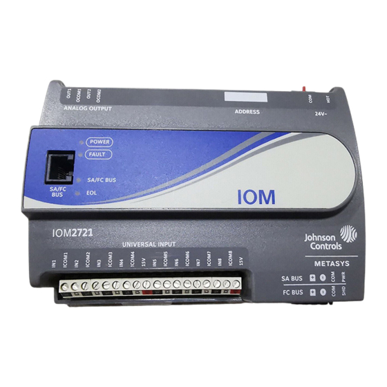
Physical features
The following figure displays the physical features of the
IOM, and the accompanying table provides a description
of the physical features and a reference to further
information where required.
Part No. 24-10144-149 Rev. L
2019-10-18
*2410144149L*
(barcode for factory use
MS-IOM2721
only)
Advertisement
Table of Contents

Related Manuals for Johnson Controls IOM2721


Summary of Contents for Johnson Controls IOM2721
- Page 1 IOM2721 Input/Output Module Installation Guide Part No. 24-10144-149 Rev. L 2019-10-18 Application Canada This Class (A) digital apparatus meets all the requirements The IOM2721 input/output expansion module is part of of the Canadian Interference-Causing Equipment the Metasys system Field Equipment Controller family. ® Regulations.
- Page 2 Figure 1: IOM2721 physical features Table 1: IOM2721 physical features callouts and • Provide for sufficient space around the expansion module for cable and wire connections for easy cover descriptions removal and good ventilation through the expansion Physical feature: description and references module (50 mm [2 in.] minimum on the top, bottom,...
- Page 3 (or anchors). Carefully d'entraîner une décharge électrique et de provoquer des blessures graves, voire mortelles. tighten all of the screws. Important: Do not overtighten the mounting screws. Overtightening the screws may damage the mounting clips. IOM2721 Input/Output Module Installation Guide...
- Page 4 See Table 4 for more information. The other controllers and expansion modules in a daisy-chain SA/FC bus Port pin assignment is shown in Figure 6. configuration using 3-wire twisted, shielded cable as shown in Figure 4. IOM2721 Input/Output Module Installation Guide...
-
Page 5: Terminal Wiring Guidelines, Functions, Ratings, And Requirements
Cable-runs over 30 m (100 ft) may require an offset in network devices. Powering network devices with the input/output software setup. uniform 24 VAC supply power phasing reduces noise, interference, and ground loop problems. The expansion module does not require an earth ground connection. IOM2721 Input/Output Module Installation Guide... - Page 6 Qualified Sensors: 0-2k ohm potentiometer, RTD (1k Nickel See Guideline A in Table 3. [ Johnson Controls sensor], 1k Platinum, and A99B Silicon Temperature Sensor) Negative Temperature Coefficient (NTC) Sensor (10k Type L, 10k JCI Type II, 2.252k Type II) Binary Input - Dry Contact Maintained Mode See Guideline A in Table 3.
- Page 7 • Shielded cable is strongly recommended for all SA and FC bus cables. • Refer to the MS/TP Communications Bus Technical Bulletin (LIT-12011034) for detailed information regarding wire size and cable length requirements for the SA and FC buses. IOM2721 Input/Output Module Installation Guide...
- Page 8 Note: See to determine wire size and cable lengths for cables. Note: The SA Bus and FC Bus wiring recommendations in this table are for MS/TP bus at 38,400 baud. For more information, refer to the MS/TP Communications Bus Technical Bulletin (LIT-12011034). IOM2721 Input/Output Module Installation Guide...
-
Page 9: Termination Details
Termination details See the figures in this section for the applicable termination diagrams. A set of Johnson Controls termination diagrams provides details for wiring inputs and outputs to the controllers. Table 5: Termination details Type of Input/ Type of field device... - Page 10 Output Current Input - Internal Source (3-wire) Current Input - External Source (in Loop) Feedback from EPP-1000 Dry Contact (Binary Input) 0–10 VDC Output to Actuator (External Source) 0–10 VDC Output to Actuator (Internal Source) IOM2721 Input/Output Module Installation Guide...
-
Page 11: Setup And Adjustments
64, 32, 16, 8, 4, 2, and 1. Switches 64 through 1 are device address switches. Switch 128 must be set to off for all hard-wired SA and FC bus applications. Switch 128 must be set to OFF for all hard-wired SA and FC Bus applications IOM2721 Input/Output Module Installation Guide... - Page 12 DIP switch block on the expansion module's cover. The following table describes the FC bus and SA bus device addresses for Johnson Controls MS/ TP communications bus applications. Table 6: SA/FC bus device address descriptions Device Address Use on Descriptions...
-
Page 13: Troubleshooting
BTCVT, which is no longer available for purchase, but continues to be supported. Troubleshooting Observe the Status LEDs on the front of the expansion module. Table 8 provides LED status indicator information for troubleshooting the expansion module. IOM2721 Input/Output Module Installation Guide... -
Page 14: Repair Information
Off Steady = EOL switch in OFF position Repair information If an expansion module fails to operate within its specifications, replace the expansion module. For a replacement expansion module, contact your Johnson Controls representative. IOM2721 Input/Output Module Installation Guide... - Page 15 Refer to the WRZ Series Wireless Room Sensors Product Bulletin (LIT-12000653) for specific WRZ Series Wireless Room Sensors sensor model descriptions. Refer to the Mobile Access Portal Gateway Catalog Page (LIT-1900869) to identify the Mobile Access Portal (MAP) Gateway appropriate product for your region. IOM2721 Input/Output Module Installation Guide...
-
Page 16: Technical Specifications
Canada: UL Listed, File E107041, CCN PAZX7 CAN/CSA C22.2 No.205, Signal Equipment Industry Canada Compliant, ICES-003 Europe: Johnson Controls declares that this product is in compliance with the essential requirements and other relevant provisions of the EMC Directive. Australia and New Zealand: RCM Mark, Australia/NZ Emissions Compliant... - Page 17 Europe NA/SA JOHNSON CONTROLS JOHNSON CONTROLS JOHNSON CONTROLS C/O CONTROLS PRODUCT WESTENDHOF 3 507 E MICHIGAN ST MANAGEMENT 45143 ESSEN MILWAUKEE WI 53202 NO. 32 CHANGJIJANG RD NEW GERMANY DISTRICT WUXI JIANGSU PROVINCE 214028 CHINA IOM2721 Input/Output Module Installation Guide...
- Page 18 © 2019 Johnson Controls. All rights reserved. All specifications and other information shown were current as of document revision and are subject to change without notice. www.johnsoncontrols.com...
Need help?
Do you have a question about the IOM2721 and is the answer not in the manual?
Questions and answers