Table of Contents
Advertisement
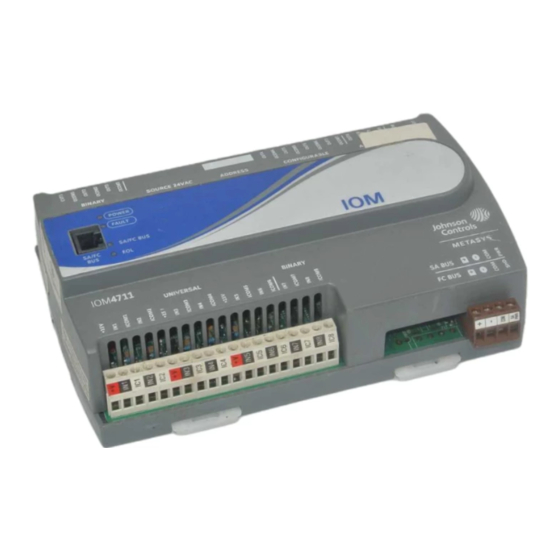
IOM47 Input/Output Module Installation Instructions
MS-IOM4711-x
Application
The IOM47 field controller is part of the Metasys® system
Field Equipment Controller family. Input/Output Module
(IOM) controller expand the number of points connected
to a Network Automation Engine (NAE), Network Control
Engine (NCE), Field Equipment Controller (FEC), or
Advanced Application Field Equipment Controller (FAC)
to monitor and control a wide variety of HVAC equipment.
IOM controllers operate on an RS-485 BACnet®
Master-Slave/Token-Passing (MS/TP) Bus as BACnet
Application Specific Controllers (B-ASCs) and integrate
into Johnson Controls® and third-party BACnet systems.
Note: At CCT Release 10.1 and later, a new capability
was introduced allowing VMAs, FECs, and FACs
to communicate by using either the BACnet or the
N2 field bus networking protocol. The I/O can be
connected through the SA bus to a host controller
that is using either the BACnet or the N2 protocol.
Only the BACnet protocol is supported when the
I/O is connected directly to the trunk using the FC
bus.
Important: In Metasys system smoke control
applications, use only the MS-IOM4711-0U
and MS-IOU4710-0U at Metasys Release
8.1 that are UL 864 UUKL/UUKLC 10th
Edition Smoke Control Listed. For Metasys
system smoke control applications, you
must refer to the Metasys System UL 864
UUKL Tenth Edition Smoke Control System
Technical Bulletin (LIT-12012487) for
detailed requirements and procedures for
installing, commissioning, and operating UL
864 UUKL/UUKLC Listed Metasys system
devices. The UL 864 UUKL/UUKLC listing
for Smoke Control Equipment is voided if
(1) you do not use the required software
tools at the required versions; or (2) you do
not meet the requirements or do not follow
the procedures as documented in the
Metasys System UL 864 UUKL Tenth
Edition Smoke Control System Technical
Bulletin (LIT-12012487).
IOM47 Input/Output Module Installation Instructions
Part No. 24-10144-92, Rev. L
Refer to the
QuickLIT website
North American Emissions
Compliance
Canada
This Class (A) digital apparatus meets all the
requirements of the Canadian Interference-Causing
Equipment Regulations.
Cet appareil numérique de la Classe (A) respecte toutes
les exigences du Règlement sur le matériel brouilleur
du Canada.
United States
This equipment has been tested and found to comply
with the limits for a Class A digital device pursuant to
Part 15 of the FCC Rules. These limits are designed to
provide reasonable protection against harmful
interference when this equipment is operated in a
commercial environment. This equipment generates,
uses, and can radiate radio frequency energy and, if not
installed and used in accordance with the instruction
manual, may cause harmful interference to radio
communications. Operation of this equipment in a
residential area may cause harmful interference, in which
case the users will be required to correct the interference
at their own expense.
Installation
Observe these guidelines when installing a controller:
•
Transport the controller in the original container to
minimize vibration and shock damage.
•
Verify that all parts shipped with the controller.
•
Do not drop the controller or subject it to physical
shock.
Parts Included
•
one controller with removable terminal blocks (Power
and SA/FC bus are removable)
•
one installation instructions sheet
Issued November 2017
for the most up-to-date version of this document.
1
Advertisement
Table of Contents

Related Manuals for Johnson Controls Metasys MS-IOM4711 Series


Summary of Contents for Johnson Controls Metasys MS-IOM4711 Series
- Page 1 Cet appareil numérique de la Classe (A) respecte toutes Application Specific Controllers (B-ASCs) and integrate les exigences du Règlement sur le matériel brouilleur into Johnson Controls® and third-party BACnet systems. du Canada. Note: At CCT Release 10.1 and later, a new capability...
-
Page 2: Materials And Special Tools Needed
Figure 1: Controller Mounting Positions Materials and Special Tools Needed • three fasteners appropriate for the mounting surface (M4 screws or #8 screws) • one 20 cm (8 in.) or longer piece of 35 mm DIN rail and appropriate hardware for DIN rail mount (only) •... - Page 3 Figure 2: Back of Controller Showing Extended Mounting Clips, DIN Rail Channel, and Mounting 4. Hold the controller in place, and insert the screws Dimensions, mm (in.) through the mounting clips and into the holes (or anchors). Carefully tighten all of the screws. Important: Do not overtighten the mounting screws.
-
Page 4: Terminal Blocks And Bus Ports
Table 1: IOM47 Physical Features Callouts and Descriptions Callout Physical Feature Description Analog Output (AO) Terminal Block, 2 – Analog Outputs. (See Table 24 VAC, Class 2 Supply Power Terminal Block. (See Table Cover Lift Tab (One of Two). (See Removing the Controller Cover.) Sensor/Actuator (SA) Bus or Field Controller (FC) Bus Terminal Block. -
Page 5: Supply Power Terminal Block
Figure 4: FC Bus Terminal Block Wiring SA/FC Bus Port The SA/FC bus port on the front of the controller is an RJ-12, 6-position modular jack that provides a connection for devices on the SA bus, a Bluetooth® Wireless Commissioning Converter, or a ZFR/ZFR Pro Wireless Router (depending on which bus the IOM is operating on). -
Page 6: Wireless Network Applications
Wireless Network Applications Figure 7: 24 VAC Supply Power Terminal Block Wiring The controller can also be installed in a wireless application using a ZFR/ZFR Pro Wireless Field Bus Router. Important: Wireless operation is not approved for smoke control applications. Refer to the Metasys System UL 864 UUKL Tenth Edition Smoke Control System Technical Bulletin (LIT-12012487) for detailed... -
Page 7: Termination Details
Termination Details A set of Johnson Controls® termination diagrams provides details for wiring inputs and outputs to the controllers. See the figures in this section for the applicable termination diagrams. Table 2: Termination Details Type of Field Device Type of... - Page 8 Table 2: Termination Details Type of Field Device Type of Termination Diagrams Input/Output Current Input - Internal Source (3 wire) Current Input - External Source (in Loop) Feedback from EPP-1000 Dry Contact (Binary Input) UI or BI 0–10 VDC Output to Actuator CO or AO (External Source) 0–10 VDC Output to Actuator...
- Page 9 Table 2: Termination Details Type of Field Device Type of Termination Diagrams Input/Output 4–20 mA Output to Actuator CO or AO 4–20 mA Output to Actuator CO or AO Voltage (Analog Output) Analog Output (Current) 24 VAC Triac Output (Switch CO or AO Low, External Source) Incremental Control to...
- Page 10 Table 2: Termination Details Type of Field Device Type of Termination Diagrams Input/Output Incremental Control to CO or AO Actuator (Switch High, Externally Sourced) Incremental Control to Actuator (Switch Low, Externally Sourced) 24 VAC Binary Output (Switch Low, Externally Sourced) 24 VAC Binary Output (Switch High, Externally Sourced) Incremental Control to...
-
Page 11: Terminal Wiring Guidelines, Functions, Ratings, And Requirements
Table 2: Termination Details Type of Field Device Type of Termination Diagrams Input/Output Network Stat with Phone Jack SA Bus (Fixed Address = 199) Network Stat with Terminals SA Bus Addressable Network Stat with Terminals SA Bus (Fixed Address = 199) Terminal Wiring Guidelines, In addition to the wiring guidelines in Table... - Page 12 Table Internal 12 V. 15k ohm pull up Qualified Sensors: 0-2k ohm potentiometer, RTD (1k Nickel [Johnson Controls® sensor], 1k Platinum, and A99B Silicon Temperature Sensor) Negative Temperature Coefficient (NTC) Sensor (10k Type L, 10k JCI Type II, 2.252k Type...
- Page 13 Table 3: IOM47 Terminal Blocks, Functions, Ratings, Requirements, and Cables Terminal Block Terminal Function, Ratings, Requirements Determine Wire Size and Label Label Maximum Cable Length ANALOG OUTn Analog Output - Voltage Mode (0–10 VDC) See Guideline C in Table (Outputs) 10 VDC maximum output voltage 10 mA maximum output current Required an external load of 1,000 ohm or more.
- Page 14 Table 3: IOM47 Terminal Blocks, Functions, Ratings, Requirements, and Cables Terminal Block Terminal Function, Ratings, Requirements Determine Wire Size and Label Label Maximum Cable Length CONFIGURABLE OUTn Analog Output - Voltage Mode (0–10 VDC) See Guideline A in Table (Outputs) 10 VDC maximum output voltage 10 mA maximum output current Required an external load of 1,000 ohm or more.
-
Page 15: Cable And Wire Length Guidelines
Cable and Wire Length Guidelines Table 4 defines cable length guidelines for the various wire sizes that may be used for wiring low-voltage (<30 V) input and outputs. Table 4: Cable Length Guidelines for Recommended Wire Sizes for Low-Voltage (<30 V) Inputs and Outputs Guideline Wire Size/Gauge and Type Maximum Cable... -
Page 16: Sa/Fc Bus And Supply Power Wiring Guidelines
In addition to the guidelines in Table 5, observe these SA/FC Bus and Supply Power guidelines when wiring an SA or FC bus and the 24 VAC Wiring Guidelines supply power: Table 5 provides information about the functions, ratings, • Run all low-voltage wiring and cables separate from and requirements for the communication bus and supply high-voltage wiring. -
Page 17: Setup And Adjustments
Note: Controllers ship with switch 128 ON and the Table 6 describes the FC bus and SA bus devices remaining address switches off rendering the addresses for Johnson Controls MS/TP controllers wired slave devices, which do not communications bus applications. operate on MS/TP buses, but will not interfere Refer to the MS/TP Communications Bus Technical with bus operation. -
Page 18: Removing The Controller Cover
Figure 10: IOM47 with Cover Removed Showing EOL Switch and Jumper Positions Table 6: SA/FC Bus Device Address Descriptions Device Use on Description Address 0 to 3 Reserved addresses for wired slave devices (not for use on controllers). (Switch 128 ON) Note: Metasys field controllers ship with switch 128 ON and the remaining address switches off rendering the controllers wired slave... -
Page 19: Input/Output Jumper Settings
Input/Output Jumper Settings UI Current Loop Jumpers The current loop fail-safe jumpers are on the circuit board Binary Output (BO) Source Power under the controller cover near the UI terminals (Figure Selection Jumpers 10). When a UI is defined (in the system software) as a 4-20 mA Analog Input and the UI’s current loop jumper is in the Disabled (default) position (Figure... -
Page 20: Troubleshooting The Controllers
Repair Information that are UL 864 10th Edition UUKL/ORD-C100-13 UUKLC If a controller fails to operate within its specifications, listed for smoke control, contact the Johnson Controls replace the controller. For a replacement controller, Repair Center in Louisville, Kentucky, at 1-502-671-7312. -
Page 21: Technical Specifications
Table 9: Accessories Ordering Information Product Code Number Description NS Series Network Sensors Refer to the NS Series Network Sensors Product Bulletin (LIT-12011574) for specific sensor model descriptions. WRZ Series Wireless Room Refer to the WRZ Series Wireless Room Sensors Product Bulletin (LIT-12000653) for specific Sensors sensor model descriptions. - Page 22 The performance specifications are nominal and conform to acceptable industry standard. For application at conditions beyond these specifications, consult the local Johnson Controls® office. Johnson Controls shall not be liable for damages resulting from misapplication or misuse of its products.
Need help?
Do you have a question about the Metasys MS-IOM4711 Series and is the answer not in the manual?
Questions and answers