Johnson Controls FX-PCX17 Installation Instructions Manual
Expansion input/ output module
Hide thumbs
Also See for FX-PCX17:
- Installation instructions manual (23 pages) ,
- Installation instructions manual (13 pages)
Table of Contents
Advertisement
Quick Links
Application
The FX-PCX17 and FX-PCX27 Expansion Input/Output Modules are part of the Facility Explorer
PC Series Programmable Controller family. FX-PCXs expansion modules expand the number of I/
O points connected to an FX-PCA, FX-PCG, or FX-PCV programmable controller or to a supervisory
controller.
The FX-PCX controllers operate on an RS-485 BACnet
Controls
and third-party BACnet systems.
®
Note: At Controller Configuration Tool (CCT) Release 10.1 and later, a new capability was
introduced allowing FX-PCVs, FX-PCGs, and FX-PCAs to communicate by using either the
BACnet or the N2 field bus networking protocol. The operation of the FX-PCX Input/Output
Module is not affected by the selection of the BACnet or the N2 protocol in the host controller
North American Emissions Compliance
Canada
This Class (A) digital apparatus meets all the requirements of the Canadian Interference-Causing
Equipment Regulations.
Cet appareil numérique de la Classe (A) respecte toutes les exigences du Règlement sur le
matériel brouilleur du Canada.
United States
This equipment has been tested and found to comply with the limits for a Class A digital device
pursuant to Part 15 of the FCC Rules. These limits are designed to provide reasonable protection
against harmful interference when this equipment is operated in a commercial environment.
This equipment generates, uses, and can radiate radio frequency energy and, if not installed
and used in accordance with the instruction manual, may cause harmful interference to
radio communications. Operation of this equipment in a residential area may cause harmful
interference, in which case the users will be required to correct the interference at their own
expense.
Installation
Observe these guidelines when installing an FX-PCX controller:
• Transport the controller in the original container to minimize vibration and shock damage.
• Verify that all parts shipped with the controller.
• Do not drop the controller or subject it to physical shock.
Part No. 24-10144-106 Rev. G
2019-03-22
FX-PCX17 and FX-PCX27 Expansion Input/
Output Module Installation Instructions
MS/TP Bus and integrate into Johnson
®
*2410144106G*
FX-PCX1711 Series, FX-PCX2711 Series
FX-
®
(barcode for factory use only)
Advertisement
Table of Contents

Related Manuals for Johnson Controls FX-PCX17


Summary of Contents for Johnson Controls FX-PCX17
- Page 1 FX-PCX17 and FX-PCX27 Expansion Input/ Output Module Installation Instructions Application The FX-PCX17 and FX-PCX27 Expansion Input/Output Modules are part of the Facility Explorer ® PC Series Programmable Controller family. FX-PCXs expansion modules expand the number of I/ O points connected to an FX-PCA, FX-PCG, or FX-PCV programmable controller or to a supervisory controller.
-
Page 2: Parts Included
• Mount the controller so that the power transformer and other devices do not radiate excessive heat to the controller. • Do not install the controller in an airtight enclosure. FX-PCX17 and FX-PCX27 Expansion Input/Output Module Installation Instructions... -
Page 3: Din Rail Mount Applications
Figure 2. Or, hold the controller up to the wall or surface in a proper mounting position and mark the hole locations through the mounting clips. FX-PCX17 and FX-PCX27 Expansion Input/Output Module Installation Instructions... - Page 4 Important: Do not overtighten the mounting screws. Overtightening the screws may damage the mounting clips. Mounting Features and Dimensions Figure 2: Back of FX-PCX17 or FX-PCX27 Controller showing extended mounting Clips, DIN rail channel and mounting dimensions, mm (in.) FX-PCX17 and FX-PCX27 Expansion Input/Output Module Installation Instructions...
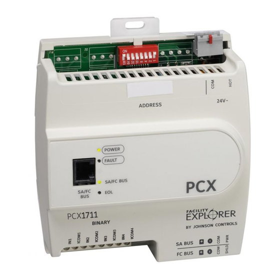
- Page 5 Sensor Actuator (SA) Bus / Field Controller (FC) Bus Terminal Block. See Table 5 for more information. Binary Inputs (BIs) Terminal Block (Not available on FX-PCX17). See Table 3 for more information. End-of-Line (EOL) Switch. See Setting the End-of-Line (EOL) switch for more information.
- Page 6 Do not exceed the controller electrical ratings. Exceeding controller electrical ratings can result in permanent damage to the controller and void any warranty. Important: Use copper conductors only. Make all wiring in accordance with local, national, and regional regulations. Important: FX-PCX17 and FX-PCX27 Expansion Input/Output Module Installation Instructions...
-
Page 7: Terminal Blocks And Bus Ports
When connecting the FX-PCX to an SA bus, wire the bus terminal block plugs on the controller and other SA bus devices in a daisy-chain configuration using 4-wire twisted, shielded cable as shown in Figure 5. See Input and Output wiring guidelines for more information. FX-PCX17 and FX-PCX27 Expansion Input/Output Module Installation Instructions... -
Page 8: Sa/Fc Bus Port
The SA/FC bus port is connected internally to the SA/FC bus terminal block. See Table 5 for more information. The SA/FC Bus Port pin assignment is shown in the Pin Number Assignments figure below. Figure 6: Pin number assignments for sensor, SA bus and FC bus ports on controllers FX-PCX17 and FX-PCX27 Expansion Input/Output Module Installation Instructions... -
Page 9: Supply Power Terminal Block
Figure 8: 24 VAC supply power terminal block wiring Note: The supply power wire colors may be different on transformers from other manufacturers. Refer to the transformer manufacturer’s instructions and the project installation drawings for wiring details. FX-PCX17 and FX-PCX27 Expansion Input/Output Module Installation Instructions... -
Page 10: Wireless Network Applications
Wireless Field Bus Router Installation Instructions (Part No. 24-10325-29). Termination details A set of Johnson Controls termination diagrams provides details for wiring inputs and outputs to the controllers. See the figures in this section for the applicable termination diagrams. Table 2: Termination details... - Page 11 Internal Source Voltage Input (Self-Powered) Current Input - External Source (Isolated) Current Input - Internal Source (2- wire) Current Input - Internal Source (3- wire) Current Input - External Source (in Loop) FX-PCX17 and FX-PCX27 Expansion Input/Output Module Installation Instructions...
- Page 12 Actuator (Switch Low, External Source) 24 VAC Binary Output (Switch Low, Externally Sourced) 24 VAC Binary Output (Switch High, Externally Sourced) Incremental Control to Actuator (Switch High, Externally Sourced) Analog Output (Current) FX-PCX17 and FX-PCX27 Expansion Input/Output Module Installation Instructions...
- Page 13 Input/ Termination diagrams device Output 4-20 mA Output to Actuator Voltage (Analog Output) 4-20 mA Output to Actuator) 0-10 VDC Output to Actuator (External Source) 0-10 VDC Output to Actuator (Internal Source) FX-PCX17 and FX-PCX27 Expansion Input/Output Module Installation Instructions...
-
Page 14: Terminal Wiring Guidelines, Functions, Ratings, And Requirements
• Inputs/outputs with cables less than 30 m (100 ft) typically do not require an offset in the software setup. Cable runs over 30 m (100 ft) may require an offset in the input/output software setup. FX-PCX17 and FX-PCX27 Expansion Input/Output Module Installation Instructions... - Page 15 Wiring ratings and requirements table Table 3: FX-PCX17 and FX-PCX27 terminal blocks, functions, ratings, requirements, and cables Determine wire size Terminal block Terminal Function, ratings, requirements and maximum cable label label length Same as (Universal) 15 VDC Power Source for active (3-wire)
- Page 16 Table 3: FX-PCX17 and FX-PCX27 terminal blocks, functions, ratings, requirements, and cables Determine wire size Terminal block Terminal Function, ratings, requirements and maximum cable label label length Binary Input - Dry Contact Maintained Mode 0.01 second minimum pulse width Internal 18 V, 3k ohm pull up...
- Page 17 Table 3: FX-PCX17 and FX-PCX27 terminal blocks, functions, ratings, requirements, and cables Determine wire size Terminal block Terminal Function, ratings, requirements and maximum cable label label length Analog Output - Voltage Mode (0–10 VDC) 10 VDC maximum output voltage 10 mA maximum output current...
-
Page 18: Cable And Wire Length Guidelines
Table 3: FX-PCX17 and FX-PCX27 terminal blocks, functions, ratings, requirements, and cables Determine wire size Terminal block Terminal Function, ratings, requirements and maximum cable label label length Normal Open Contact The Relay output terminals can Connects OCOM to OUT NO when activated. -
Page 19: Cable Length Guidelines For Recommended Wire Size
Note: Figure 9 applies to low-voltage (<30 V) inputs and outputs only. The required wire size and length for high-voltage (>30 V) Relay Outputs is determined by the load connected to the relay and local electrical codes. FX-PCX17 and FX-PCX27 Expansion Input/Output Module Installation Instructions... -
Page 20: Max Wire Length By Current And Wire Size Graphic
• Refer to the FX-PC Series ControllersMS/TP Communications Bus Technical Bulletin (LIT-12011670) or MS/TP Communications Bus for BCPro System Technical Bulletin (LIT-12011908) for detailed information regarding wire size and cable length requirements for the SA and FC buses. FX-PCX17 and FX-PCX27 Expansion Input/Output Module Installation Instructions... -
Page 21: Comm Bus And Power Supply Terminal Block Rating And Requirements Table
Note: The SA Bus and FC Bus wiring recommendations in this table are for MS/TP bus communications at 38,400 baud. For more information, refer to the FX-PC Series ControllersMS/ TP Communications Bus Technical Bulletin (LIT-12011670) or MS/TP Communications Bus for BCPro System Technical Bulletin (LIT-12011908). FX-PCX17 and FX-PCX27 Expansion Input/Output Module Installation Instructions... -
Page 22: Setup And Adjustments
Set switch 128 to ON only for controllers on an FX-ZFR/ZFR Pro Series Wireless Field Bus application. For all hard-wired SA and FC bus applications, ensure that switch 128 is set to Off. FX-PCX17 and FX-PCX27 Expansion Input/Output Module Installation Instructions... -
Page 23: Removing The Controller Cover
Write each controller's device address on the white label below the DIP switch block on the controller's cover. Table 6 describes the FC bus and SA bus devices addresses for Johnson Controls MS/TP communica- tions bus applications. Refer to the FX-PC Series ControllersMS/TP Communications Bus Technical Bulletin (LIT-12011670) or MS/ TP Communications Bus for BCPro System Technical Bulletin (LIT-12011908) for more information on controller device addresses and how to set them on MS/TP buses. -
Page 24: Cover Removed Eol Switch
Replace the cover by placing it squarely over the base, and then gently and evenly push the cover on to the latches until they snap into the latched position. Cover Removed EOL switch Figure 11: FX-PCX17 or FX-PCX27 with cover removed showing EOL switch location Setting the End-of-Line (EOL) switch About this task: Each controller has an EOL switch, which, when set to ON, sets the controller as a terminating device on the bus. -
Page 25: Commissioning The Controllers
Note: The MAP Gateway serves as a replacement for the BTCVT, which is no longer available for purchase, but continues to be supported. Troubleshooting the Controllers Observe the Status LEDs on the front of the controller and see Table 7 to troubleshoot the controller. FX-PCX17 and FX-PCX27 Expansion Input/Output Module Installation Instructions... -
Page 26: Led Status And Description Table
Table 8: Accessories ordering information Product Code Number Description FX-BTCVT-1 Bluetooth Commissioning Converter, with Bluetooth Technology ® FX-ZFR1811-0 Wireless Field Bus Router Transformer, 120 VAC Primary to 24 VAC secondary, 20 VA, Wall TP-2420 Plug FX-PCX17 and FX-PCX27 Expansion Input/Output Module Installation Instructions... -
Page 27: Technical Specifications
Bus System Technical Bulletin (LIT-12011660) or FX-ZFR Series Wireless Field Bus System Quick Reference Guide (LIT-12011696). Technical specifications Table 9: FX-PCX17 and FX-PCX27 technical specifications FX-PCX1711 Series Expansion Input/Output Module FX-PCX2711 Series Expansion Input/Output Module Product Code Numbers FX-PCX17 and FX-PCX27 Expansion Input/Output Module Installation Instructions... - Page 28 1/4 hp 120 VAC, 1/2 hp 240 VAC 360 VA Pilot Duty at 120/240 VAC (B300) 3 A Non-inductive 24-240 VAC CE Marking (-2 model only): 6 (4) A N.O. or N.C. only, 240 VAC FX-PCX17 and FX-PCX27 Expansion Input/Output Module Installation Instructions...
- Page 29 Note: Mounting space requires an additional 50 mm (2 in.) Depth) space on top, bottom and front face of controller for easy cover removal, ventilation and wire terminations. Weight 0.5 kg (1.1 lb) maximum FX-PCX17 and FX-PCX27 Expansion Input/Output Module Installation Instructions...
- Page 30 Protocol Revision 4 Listed BACnet Application Specific Controller (B-ASC) The performance specifications are nominal and conform to acceptable industry standard. For application at conditions beyond these specifications, consult the local Johnson Controls office. Johnson ® Controls shall not be liable for damages resulting from misapplication or misuse of its products.
Need help?
Do you have a question about the FX-PCX17 and is the answer not in the manual?
Questions and answers