Johnson Controls FX-PCX17 Installation Instructions Manual
Hide thumbs
Also See for FX-PCX17:
- Installation instructions manual (23 pages) ,
- Installation instructions manual (31 pages)
Advertisement
FX-PCX17 and FX-PCX27
Installation Instructions
FX-PCX1711-x
FX-PCX2711-x
Applications
The FX-PCX17 and FX-PCX27 Expansion
Input/Output Modules are part of the Facility Explorer
FX-PC family. FX-PCXs expand the number of inputs
and outputs connected to FX-PCs to monitor and
control a wide variety of Heating, Ventilating, and Air
Conditioning (HVAC) applications.
The FX-PCXs operate on an RS-485 BACnet®
Master-Slave/Token-Passing (MS/TP) Bus and
integrate into the Web based Facility Explorer.
North American Emissions Compliance
Canada
This Class (A) digital apparatus meets all the
requirements of the Canadian Interference-Causing
Equipment Regulations.
Cet appareil numérique de la Classe (A) respecte
toutes les exigences du Règlement sur le matériel
brouilleur du Canada.
United States
This equipment has been tested and found to
comply with the limits for a Class A digital device
pursuant to Part 15 of the FCC Rules. These limits
are designed to provide reasonable protection
against harmful interference when this equipment is
operated in a commercial environment. This
equipment generates, uses, and can radiate radio
frequency energy and, if not installed and used in
accordance with the instruction manual, may cause
harmful interference to radio communications.
Operation of this equipment in a residential area is
likely to cause harmful interference, in which case
the user will be required to correct the interference
at his/her own expense.
Installation
Observe these guidelines when installing an FX-PCX:
•
Transport the FX-PCX in the original container to
minimize vibration and shock damage.
•
Verify that all parts shipped with the FX-PCX.
Refer to the
QuickLIT Web site
•
Do not drop the FX-PCX or subject it to physical
shock.
Parts Included
•
one FX-PCX17 or FX-PCX27 controller with
removable terminal blocks
•
one installation instructions sheet
Materials and Special Tools Needed
•
three fasteners appropriate for the mounting
surface (M4 screws or #8 screws)
•
one 20 cm (8 in.) or longer piece of 35 mm DIN rail
and appropriate hardware for DIN rail mount (only)
•
small straight blade screwdriver for securing wires
in the terminal blocks
Mounting
Observe these guidelines when mounting an FX-PCX:
•
Ensure the mounting surface can support the
FX-PCX, DIN rail, and any user-supplied
enclosure.
•
Mount the FX-PCX on 35 mm DIN rail whenever
possible.
•
Mount the FX-PCX in the proper mounting position
(Figure 1).
•
Mount the FX-PCX on a hard, even surface
whenever possible in wall-mount applications.
•
Use shims or washers to mount the FX-PCX
securely and evenly on the mounting surface.
•
Mount the FX-PCX in an area free of corrosive
vapors and observe the Ambient Conditions in the
Technical Specifications section.
•
Provide for sufficient space around the FX-PCX for
cable and wire connections, easy cover removal,
and good ventilation through the controller (50 mm
[2 in.] minimum on the top, bottom, and front of the
controllers).
•
Do not mount the FX-PCX on surfaces prone to
vibration, such as duct work, or in areas where
electromagnetic emissions from other devices or
wiring can interfere with controller communication.
FX-PCX17 and FX-PCX27 Installation Instructions
Part No. 24-10144-106, Rev. —
Issued April 12, 2011
for the most up-to-date version of this document.
1
Advertisement
Table of Contents

Related Manuals for Johnson Controls FX-PCX17


Summary of Contents for Johnson Controls FX-PCX17
- Page 1 Input/Output Modules are part of the Facility Explorer Parts Included FX-PC family. FX-PCXs expand the number of inputs • one FX-PCX17 or FX-PCX27 controller with and outputs connected to FX-PCs to monitor and removable terminal blocks control a wide variety of Heating, Ventilating, and Air •...
-
Page 2: Din Rail Mount Applications
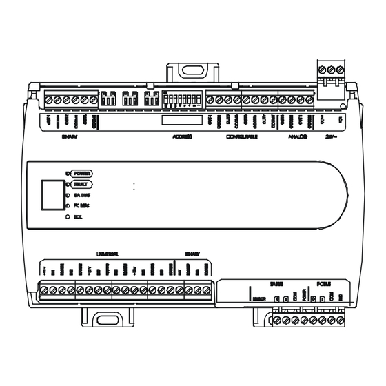
(if necessary). 4. Hold the FX-PCX in place, and insert the screws through the mounting clips and into the holes. Figure 2: Back of FX-PCX17 and FX-PCX27 Carefully tighten all of the screws. Controller Showing Extended Mounting Clips, DIN Rail Channel, and Mounting Dimensions, mm (in.) - Page 3 Figure 3: FX-PCX1711 Controller Physical Features and Wiring Terminals Figure 4: FX-PCX2711 Controller Physical Features and Wiring Terminals FX-PCX17 and FX-PCX27 Installation Instructions...
- Page 4 FX-PCX Terminal Blocks and Bus Ports SA Bus See Figure 3 and Figure 4 for terminal block and bus Terminal Cable Shield Block Plugs port locations on the FX-PCX17 and FX-PCX27 Connection controllers. Observe the following guidelines when wiring an FX-PCX. To Next To Next...
-
Page 5: Wireless Network Applications
FX-PCX and all other network devices so that transformer phasing is uniform across the network devices. Powering network devices with uniform 24 VAC supply power phasing reduces noise, interference, and ground loop problems. The FX-PCX does not require an earth ground connection. FX-PCX17 and FX-PCX27 Installation Instructions... - Page 6 See Guideline A in Table 2. Internal 12 V, 15k ohm pull up Qualified Sensors: 0-2k potentiometer, RTD (1k Nickel [Johnson Controls® sensor], 1k Platinum, and A99B Silicon Temperature Sensor) Negative Temperature Coefficient (NTC) Sensor (10k Type L, 10k JCI Type II, 2.252k Type II) Binary Input - Dry Contact Maintained Mode See Guideline A in Table 2.
- Page 7 183 m (600 ft) twisted wire 0.6 mm (22 AWG) stranded copper the setup software for the input or output point. N/A (24 AWG) stranded copper 107 m (350 ft) twisted wire FX-PCX17 and FX-PCX27 Installation Instructions...
- Page 8 45.7 m (150 ft) 0.6 mm (22 AWG) 30.5 m 100 ft N/A (24 AWG ) 15.2 m 50 ft 0 m 0 ft Load Current (mA) Figure 9: Maximum Wire Length by Current and Wire Size FX-PCX17 and FX-PCX27 Installation Instructions...
- Page 9 See Table 2 to determine wire size and cable lengths for cables other than the recommended cables. The SA Bus and FC Bus wiring recommendations in this table are for MS/TP bus communications at 38.4k baud. For more information, refer to the FX-PC Series Controllers MS/TP Communications Bus Technical Bulletin (LIT-12011670). FX-PCX17 and FX-PCX27 Installation Instructions...
-
Page 10: Setup And Adjustments
Table 4 shows and describes the valid FC Bus and SA Bus devices addresses for Johnson Controls® MS/TP communications bus applications. Table 4: SA/FC Bus Device Address Descriptions Figure 11: FX-PCX17 or FX-PCX27 with Cover Device Description Removed Showing EOL Switch Position Address Reserved for FC Bus supervisory controller. -
Page 11: Troubleshooting
See Table 6 to order accessories. operate within its specifications, replace the unit. For a replacement controller, contact the nearest Johnson Controls representative. Table 6: FX-PCX17 and FX-PCX27 Controller Accessories Ordering Information (Part 1 of 2) Product Code Number Description FX-BTCVT-1... -
Page 12: Technical Specifications
Table 6: FX-PCX17 and FX-PCX27 Controller Accessories Ordering Information (Part 2 of 2) Product Code Number Description AP-TBK4FC-0 Replacement MS/TP FC Bus Terminal, 4-Position, Blue, Bulk Pack AP-TBK3PW-0 Replacement Power Terminal, 3-Position Connector, Gray, Bulk Pack Additional Y6X Series Transformers are also available. Refer to the Series Y63, Y64, Y65, and Y69 Transformers Product Bulletin (LIT-125755) for additional models. - Page 13 The performance specifications are nominal and conform to acceptable industry standard. For application at conditions beyond these specifications, consult the local Johnson Controls® office. Johnson Controls, Inc. shall not be liable for damages resulting from misapplication or misuse of its products.
Need help?
Do you have a question about the FX-PCX17 and is the answer not in the manual?
Questions and answers