
Related Manuals for GEA VARIVENT 24/7 PMO


Summary of Contents for GEA VARIVENT 24/7 PMO
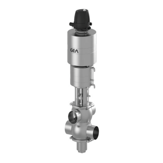
- Page 1 Original Operating Instructions VARIVENT 24/7 PMO Cheese Curd Valve 2.0 Type: M_C/2.0 ® Edition 2018-10-04 430BAL013215EN_1...
- Page 2 Machinery directive.These operating instructions are protected by copyright. All rights reserved. The document may not, in whole or in part, be copied, reproduced, translated or reduced to an electronic medium of machine-readable form without the express permission of GEA Tuchenhagen GmbH. ® ®...
-
Page 3: Table Of Contents
Table of Contents Notes for the Reader ............................6 Binding Character of These Operating instructions ..................6 Notes on the Illustrations ..........................6 Symbols and Highlighting ..........................7 Abbreviations and Terms ..........................8 Safety ................................10 Safety Note ..............................10 Operator's Duties ............................ - Page 4 Hosing Diagram............................. 32 Electrical Connections and Commissioning ....................33 Connecting the valve............................33 Adjusting the Position Detecting Devices......................34 • Adjusting Control top T.VIS A-15 ........................ 34 • Adjusting Control top T.VIS M-15 ....................... 36 • Adjusting the Proximity Switch in the Lantern on Double-Disks Without Balancer........39 •...
- Page 5 Disposal ................................74 • General Notes ............................74 • Valve Actuator Disposal ..........................75 Technical Data .............................. 76 Type Plate ..............................76 Technical Data ............................... 76 Resistance of Sealing Materials ........................78 Pipe Ends ............................... 79 Weights ................................79 Tools ................................80 Lubricants ...............................
-
Page 6: Notes For The Reader
Notes for the Reader Notes on the Illustrations Notes for the Reader The present Operating instructions are part of the user information for the valve. The Operating instructions contain all the information you need to transport, install, commis- sion, operate and carry out maintenance for the valve. Binding Character of These Operating instructions These Operating instructions contains the manufacturer's instructions for the owner of the valve and for all persons who work on or use the valve regarding the procedures to... -
Page 7: Symbols And Highlighting
Notes for the Reader Symbols and Highlighting Symbols and Highlighting In these Operating instructions important information is highlighted by symbols or special formatting. The following examples illustrate the most important types of high- lighting. DANGER Warning: Fatal Injuries. Failure to observe the warning can cause serious damage to health, or even death. ... -
Page 8: Abbreviations And Terms
Notes for the Reader Abbreviations and Terms NOTE Further useful information. Abbreviations and Terms Abbreviation Explanation Indicates the size of spanners width across flats approx. approximately British Standard Unit of measurement of pressure [bar] All pressure ratings [bar/psi] stand for over pressure [bar /psi if this is not explicitly described differently. - Page 9 Notes for the Reader Abbreviations and Terms Abbreviation Explanation Unit of measurement of force [kilonewton] Unit of measurement of volume [litre] max. maximum Unit of measurement of length [millimetre] μm Unit of measurement of length [micrometre] metric Unit of measurement of work [newton metre] 1 Nm = 0.737 lbft NIT OF TORQUE Pound-Force (lb) + Feet (ft)
-
Page 10: Safety
Safety Operator's Duties Safety Safety Note The valve is operationally reliable. It was built according to state-of-the art standards. Nevertheless, the valve can pose dangers, especially if • the valve is not used in accordance with its intended use, • the valve is not used correctly, •... -
Page 11: Qualification Of Staff
Safety Qualification of Staff Qualification of Staff This section contains information about the qualifications that staff working on the valve must have. Operating and maintenance staff must • have the necessary qualification to carry out their tasks, • be instructed with regard to possible dangers, •... -
Page 12: Supplementary Regulations
Safety Supplementary Regulations For work to be carried out on the valve the following user groups are distinguished: User groups Staff Qualifications Operating staff Adequate instruction and sound knowledge in the following areas: • Function of the valve • Valve operating sequences •... -
Page 13: Instructions For The Safe Operation
Safety Instructions for the Safe Operation Instructions for the Safe Operation Dangerous situations during the operation can be avoided by safety-conscious and proactive behaviour of the staff. General Principles To ensure the safe operation of the valve the following principles apply: •... -
Page 14: Installation
Safety Instructions for the Safe Operation Installation For installation, the following principles apply: • Only properly qualified staff is allowed to install, assemble and set the valve into operation. • Ensure that adequate working and traffic areas are available at the place of installa- tion. -
Page 15: Setting Into Operation
Safety Instructions for the Safe Operation Setting into Operation For setting into operation, the following principles apply: • Only allow properly qualified staff to set the valve into operation. • Establish all connections correctly. • The safety devices for the valve must be complete, fully functional and in perfect condition. -
Page 16: Maintenance And Repair
Safety Instructions for the Safe Operation Maintenance and Repair Before starting any maintenance and repair work on the electrical devices of the valve, carry out the following steps in accordance with the "5 safety rules": • Isolate from the power supply •... -
Page 17: Disassembly
Safety Instructions for the Safe Operation Disassembly For disassembly, the following principles apply: • Only allow qualified staff to disassemble the valve. • Before starting disassembly, the valve must be switched off and secured against being switched back on. Work may only be started once any residual energy has been discharged. -
Page 18: Signage
Safety Signage Signage Dangerous points on the valve are indicated by warning signs, prohibition signs and mandatory signs. The signs and notes on the valve must always be legible. Any illegible signs must be replaced immediately. Signs on the valve Sign Meaning General hazard warning... -
Page 19: Residual Risk
Safety Residual Risk Residual Risk Hazard Areas Please observe the following notes: • In the event of malfunctions, shut down the valve (disconnect from the power and air supply) and secure it against being used. • Never reach into the lantern (9) or the valve housing when the valve is switching. Fingers can be crushed or cut off. - Page 20 Safety Residual Risk • If work on live parts cannot be avoided, call in a second person, who can operate the main switch in case of an emergency. • The housing sockets have very sharp edges. When transporting and assembling the valve be sure to wear suitable protective gloves.
-
Page 21: Residual Dangers
Cover or safeguard any adjacent live parts. Spring tension in the actuator Danger to life caused by compression spring in the actuator. Do not open the actuator but return it to GEA Tuchenhagen for proper disposal. Danger of injury Danger presented by moving or The operator must exercise caution and prudence. -
Page 22: Declaration Of Conformity
2006/42/EC Applicable harmonized standards: DIN EN ISO 12100 Authorised representative for compilation Authorised representative – of the technical documentation CE documentation GEA Tuchenhagen GmbH Am Industriepark 2-10 21514 Büchen Büchen, 16/02/2015 Franz Bürmann i.V. Matthias Südel Managing Director Team Leader Product Development ®... -
Page 23: Transport And Storage
Transport and Storage Transport Transport and Storage Scope of Supply On receipt of the valve check whether • the details on the type plate correspond to the data in the order and delivery docu- ments, • the equipment is complete and all components are in good order. Transport For transport, the following principles apply: •... -
Page 24: Storage
Transport and Storage Storage Storage Valves, valve inserts or spare parts should be stored in a dry place, free of vibrations and dust. To avoid damage, leave the components in their original packaging if possible. If, during transport or storage, the valve is going to be exposed to temperatures ≤ 0°C, it must be dried and suitable measures be taken to protect it from damage. -
Page 25: Intended Purpose
The mixproof valves M/2.0 are pressure equipment (without safety function) in the sense of the pressure equipment directive: Directive 97/23/EC. They are classified according to Annex II, article 3, section 3. In the event of any deviations, GEA Tuchenhagen GmbH will supply a special Declaration of Conformity. -
Page 26: Conversion Work
EC Machinery Direc- tive on your own. In general, only original spare parts supplied by GEA Tuchenhagen GmbH should be fitted. This ensures the reliable and economical operation of the valve. -
Page 27: Design And Function
Design and Function Design Design and Function Design Designation Designation actuator lantern control top T.VIS valve disk sealing ring double valve disk rod guide ring lifting actuator sealing disk valve housing O-ring Sterile lock MMU V-ring RA... -
Page 28: Leakageproof Shut-Off
Design and Function Actuator Function Leakageproof Shut-off In mixproof valve M/2.0, the upper and the lower valve housing are each fitted with a valve seat.The chamber between the valve disks is connected to the open environment by an isolation outlet integrated into the lower valve spindle. Should seal damage occur, leaking fluid flows safely into the open. -
Page 29: Installation
Installation Valve with Detachable Pipe Connection Elements Installation Notes on Installation The standard installation position of the valve is upright and in no case more than 15 degrees to the vertical. However, care must be taken to ensure that the valve housing and the pipe system can drain properly. -
Page 30: Valve With Welding Ends
Installation Valve with Welding Ends Valve with Welding Ends This section describes the welding procedure for the valve. Installation position of the valve housing WARNING Spring tension in the valve Danger of injury when opening the clamps (43) as the released spring pretension will suddenly lift the actuator. -
Page 31: Pneumatic Connections
Installation Pneumatic Connections Assemble the valve and depressurize the actuator. The valve disk is lowered. Done NOTE When assembling the valve always replace the housing O-rings to ensure that the valve is tight. Pneumatic Connections Air requirement Size Type Air requirement Air requirement... -
Page 32: Hosing Diagram
Hosing Diagram Date: 2012-03-19 Page: 32 221BAL009233.fm ® VARIVENT Mixproof Valve M/2.0 Hosing Diagram ® Mixproof Valve M-C/2.0 Operating Instructions · VARIVENT Edition 2018-10-04... -
Page 33: Electrical Connections And Commissioning
Electrical Connections and Commissioning Connecting the valve Electrical Connections and Commissioning Connecting the valve DANGER Live parts Electrical shock can result in serious personal injury or death. Only allow properly qualified staff to carry out work on the electrical equipment. ... -
Page 34: Adjusting The Position Detecting Devices
Electrical Connections and Commissioning Adjusting the Position Detecting Devices Adjusting the Position Detecting Devices The control top and lantern sensors are adjusted at the factory. During transportation or installation these settings may alter and re-adjustment may be necessary (see operating instructions Control top T.VIS M-15 or T.VIS A-15). - Page 35 Electrical Connections and Commissioning Adjusting the Position Detecting Devices Within 30 seconds of power up, simultaneously press both black buttons (A, B) on the top of the control top for 3 to 7 seconds. The set-up will proceed automatically. This will take approx. 60 seconds. Do not press any buttons during the 60 second set up procedure irrespective of the colors or flashing of the LED.
-
Page 36: Adjusting Control Top T.vis M-15
Electrical Connections and Commissioning Adjusting the Position Detecting Devices Adjusting Control top T.VIS M-15 For the Start Position of the Valve Disk – Valve Non-actuated Clockwise rotation of the setting screw (1) moves the sensor upwards, anti-clock- Requirement wise rotation downwards. Presetting CAUTION Danger if media are present in the valve when this is actuated! - Page 37 Electrical Connections and Commissioning Adjusting the Position Detecting Devices Turn setting screw (1) of the sensor S1, until light emitting diode D1 at the interface top shines green. Move sensor using the setting screw (1) in the direction of the lower switching edge (4) of the switching range (3) until the diode turnes off.
- Page 38 Electrical Connections and Commissioning Adjusting the Position Detecting Devices Turn setting screw (1) of the sensor S2, until light emitting D2 at the interface top shines yellow. Move sensor using the setting screw (1) in the direction of the upper switching edge (4) of the switching range (3) until the diode turnes off.
-
Page 39: Adjusting The Proximity Switch In The Lantern On Double-Disks Without Balancer
Electrical Connections and Commissioning Adjusting the Position Detecting Devices Adjusting the Proximity Switch in the Lantern on Double-Disks Without Balancer This section only applies for double-disks without balancer on VARIVENT valves D, R, Y and B. Fitting the proximity Carry out the following steps: switch holder Preassemble sliding piece (1), countersunk screw (3) and nut NI (2). - Page 40 Electrical Connections and Commissioning Adjusting the Position Detecting Devices Fitting the proximity Carry out the following steps: switch Remove the adjusting screw. Screw proximity switch M12 (8) into the proximity switch holder until the cleaning connection (7) is reached. Adjusting the prox- Carry out the following steps: imity switch Unscrew the proximity switch by one full turn (360°) to set the gap (a) in the range...
-
Page 41: Adjusting Of The External Sensor In The Lantern
Electrical Connections and Commissioning Adjusting the Position Detecting Devices Adjusting of the external Sensor in the Lantern Fitting the proximity Carry out the following steps: switch holder Place the proximity switch nut (2) against the slot (4.1) from the inside of the lantern (4) and hold it in position with a finger. - Page 42 Electrical Connections and Commissioning Adjusting the Position Detecting Devices Adjusting the prox- Carry out the following steps: imity switch holder Screw the adjusting screw (6) into the proximity switch holder down to the upper edge of the balancer (7). By slightly slackening the countersunk screw, position the proximity switch holder in the slot in the lantern so that the point of the adjusting screw (6) rests on the shoulder of the balancer in the direction of the actuator (A).
- Page 43 Electrical Connections and Commissioning Adjusting the Position Detecting Devices Fitting the Carry out the following steps: proximity switch Remove the adjusting screw (6). Screw the proximity switch M12 (8) into the proximity switch holder up to the balancer (7) together with counter nut (11). Carry out the following steps: Adjusting the proximity switch...
- Page 44 Electrical Connections and Commissioning Adjusting the Position Detecting Devices Fitting the proximity Carry out the following steps: switch holder Place the proximity switch nut (2) against the slot (4.1) from the inside of the lantern (4) and hold it in position with a finger. Fix the sliding piece (1) with the countersunk screw (3) in the orientation shown –...
- Page 45 Electrical Connections and Commissioning Adjusting the Position Detecting Devices By slightly slackening the countersunk screw, position the proximity switch holder in the slot in the lantern so that the point of the adjusting screw (6) rests on the shoulder of the balancer in the direction of the actuator (A). Fix the proximity switch holder in position with the countersunk screw (3).
- Page 46 Electrical Connections and Commissioning Adjusting the Position Detecting Devices Adjusting the Carry out the following steps: proximity switch Unscrew the proximity switch a full rotation (360°), to adjust distance (a) up 0.5 to 1.0 mm. Tighten counternut (11). Secure the connector (10), which has already been electrically connected to the control top, to the proximity switch using the cap nut M12 (10.1).
-
Page 47: Test Procedures For Tuchenhagen Pmo Valve Type M-C/2.0
Electrical Connections and Commissioning Test Procedures for Tuchenhagen PMO Valve Type M-C/2.O Test Procedures for Tuchenhagen PMO Valve Type M-C/2.O Purpose • The purpose of test procedure 1 is for the Regulatory Inspector to check and ensure that the detecting devices which detect and confirm the closed position of the upper and lower seats of the PMO valve respectively (as per PMO Item 15p.(B) - Point 1.b.(2)) are adjusted and functioning properly. -
Page 48: Test Procedure 1
Electrical Connections and Commissioning Test Procedures for Tuchenhagen PMO Valve Type M-C/2.O Test procedure 1 Step 1 The valve should be in the closed position. This can be seen by the GREEN LED on the top of the control top. Step 2 Carry out the following steps: ... -
Page 49: Test Procedure 2
Electrical Connections and Commissioning Test Procedures for Tuchenhagen PMO Valve Type M-C/2.O Test procedure 2 The methology behind test procedure 2 is to allow the Regulatory Inspector to manually force open the seat opposite to the valve housing which is part of an active CIP circuit to ensure that proper control system interlocking is in place. -
Page 50: Cleaning And Passivation
Cleaning and Passivation Cleaning Cleaning and Passivation Cleaning All parts in contact with product must be cleaned at regular intervals. Always observe the safety data sheets issued by the cleaning agent manufacturers. Only use cleaning agents which do not cause damage to the seals and inner valve parts. During pipe cleaning, the cleaning fluid also flows through the valve housings and cleans them. -
Page 51: Examples Of Cleaning By Lifting
Cleaning and Passivation Passivation We recommend that the cleaning parameters for the system should be defined during the test phase in order to save cleaning medium. To optimize seat cleaning, spot checks on the valve are performed after cleaning to ascertain whether the valve seats and the sealing surfaces are clean. -
Page 52: Malfunctions
Malfunctions Malfunctions In the event of malfunctions immediately deactivate the valve and secure it against inad- vertent reactivation. Malfunctions may only be remedied by qualified staff, who must observe the safety instructions. Malfunction Cause Remedy Valve does not work Fault in the Check the system configura- tion control system... -
Page 53: Maintenance
Maintenance Inspections Maintenance Inspections Between the maintenance periods, the valves must be checked for leakage and proper function. Product Contact Seals Carry out the following steps: Regularly check: – Upper sealing ring – Lower sealing ring – V-ring in the valve disks. Deficiency visible at the leakage on the leakage outlet during the closed position of the valve. -
Page 54: Maintenance Intervals
Maintenance Prior to dismantling the Valve Maintenance Intervals To ensure the highest operational reliability of the valves, all wearing parts should be replaced at longer intervals. The actual maintenance intervals can only be determined by the user since they depend on the operating conditions, for instance: •... -
Page 55: Disassembling
Maintenance Disassembling Disassembling Depressurizing the Actuator WARNING Spring tension in the valve Danger of injury when opening the clamps (43) as the released spring pretension will suddenly lift the actuator. Therefore, release the spring tension before detaching the clamps by pressurizing the actuator with compressed air at max. -
Page 56: Removing The Control Top And The Switch Bar
Maintenance Disassembling Removing the Control Top and the Switch Bar No solenoid valve must be actuated electrically or manually. Requirement The pneumatic and electrical connections on the plant side can remain on the control top. IMPORTANT NOTE The permanent magnet on the switch bar (1) is fragile. Damage to the permanent magnet. -
Page 57: Separating The Valve From The Housing
Maintenance Disassembling Separating the Valve from the Housing IMPORTANT NOTE The valve disks (B) are a sensitive components. The sealing surfaces on the valve disks (B) may be damaged. Take care when removing the valve insert from the housing that the valve disks do not hit the valve housing. -
Page 58: Dismantling The Valve Disk
Maintenance Disassembling Dismantling the Valve Disk Carry out the following steps: Remove clamp jointClamp joint (46). Pull actuator (A) out of the lifting actuator (L1). Remove locking flange (L3). Hold carrier (L2) using a tubular hex. box spanner size 36, set the head face spanner at (15.1) and unscrew valve disk (15). -
Page 59: Dismantling The Double Valve Disk
Maintenance Disassembling Dismantling the Double Valve Disk IMPORTANT NOTE The double valve disk and the sealing disk are sensitive components. The sealing surfaces on the double valve disk and the sealing disk may be damaged. Take care when removing the double valve disk. IMPORTANT NOTE The deflection edges on the double valve disk are sensitive parts. -
Page 60: Dismantling The Lifting Actuator
Maintenance Disassembling Insert pin punch into the bore (16.1) and unscrew double valve disk (16). Withdraw sealing disk (3) with rod guide ring (2), O-ring (5), sealing ring (1) from the lantern (9). Done Dismantling the Lifting Actuator It is not necessary, to change the O-rings in the lifting actuator at every service. ®... -
Page 61: Maintenance
Maintenance Maintenance Carry out the following steps: Pull-off CIP connection (91) from the carrier sleeve (L6). Put lifting actuator (L1) down for further disassembly. Push the piston (L1.4) with fitted carrier (L2) and carrier sleeve (L6) upwards against the lifting actuator flange (L1.1) and remove the circlip (L7) from the piston (L1.4) using nippers. -
Page 62: Removing V-Ring Ra
Maintenance Maintenance Removing V-Ring RA CAUTION The scriber can slip off when the V-ring RA is removed. Danger of injury and damaging the valve disk! Grip the valve disk in a vice with protected jaws. Carry out the following steps: ... -
Page 63: Inserting V-Ring Ra
Maintenance Maintenance Inserting V-Ring RA Insertion tool Insert V-rings without grease. Requirement We recommend using water with household dish washing detergent (1 drop/1 l; 4 drops/US GAL) as an aid for the insertion of V-rings. In order that no rust is transferred, the washing-up liquid solution must be made up in a ceramic, plastic, or stainless steel container. -
Page 64: Lubricating Seals And Threads
Maintenance Maintenance Check that the V-Ring is properly in position and that there are no dents. Done NOTE Used seals must not be used again, since the proper function of the seal can no longer be ensured. Lubricating Seals and Threads CAUTION Damage to seals and threads Damage to seals and threads can result in a malfunction. - Page 65 They have the NSF- H1 (USDA H1) registration. PARALIQ GTE 703 can be ordered from GEA Tuchenhagen under part no. 413-064, and Rivolta F.L.G. MD-2 can be ordered under part no. 413- 071.
-
Page 66: Assembling
Maintenance Assembling Assembling Assembling the Lifting Actuator Carry out the following steps: Equip the lifting actuator M/2.0 (L1) with O-rings (L18, L19, L20) and fix it at the lantern (9) with 4 hex. screws (110). ® Mixproof Valve M-C/2.0 Operating Instructions · VARIVENT Edition 2018-10-04... - Page 67 Maintenance Assembling Place O-ring (13.2) into the carrier sleeve (L6) and provide bushing (L5) with O-rings (L12, L13.1) and place it also into the carrier sleeve (L6). Or with help of the mandrel, part no. 221-105.94 or 221-105.95 Provide bushing (L5) with O-rings (L12, L13.1) and plug it on to the mandrel. Then place O-ring (L13.2) on the top and push everything into the carrier sleeve (L6).
-
Page 68: Assembling The Valve
Maintenance Assembling Assembling the Valve IMPORTANT NOTE The deflection edges (16.2) on the double valve disk are sensitive parts. The edges on the double valve disk may be damaged. The deflection edges must be handeld with care. Carry out the following steps: Push CIP connection (91) equipped with O-rings (108, 109) on to the carrier sleeve (L6). - Page 69 Maintenance Assembling Hold carrier sleeve at (Z) using a hook spanner.
- Page 70 Maintenance Assembling Tighten the double valve disk (16) complete with V-ring RA (7), snap sealing (74), O- ring (72), sealing disk (3), O-ring (5), sealing ring (1), rod guide ring (2) by applying a pin punch at (16.1). While screwing the double valve disk, press the sealing disk (3) against the lantern (9).
- Page 71 Maintenance Assembling Hold carrier (L2) with tubular hex. box spanner size 36 and tighten valve disk (15) together with installed V-ring (94) with flexible head face spanner at (15.1). Insert locking flange (L3) into the lifting actuator (L1). Insert actuator (A) into the lifting actuator (L1) and fix with clamp joint (46). ...
-
Page 72: Mounting The Switching Rod And The Control Top
Maintenance Assembling Mounting the Switching Rod and the Control Top IMPORTANT NOTE The permanent magnet on the switch bar is fragile. Damage to the permanent magnet. Protect the permanent magnet against impact stress. Carry out the following steps: Screw the sliding piece (1.2) into the piston rod using a 12 mm slotted screw driver, tightening torque 2 Nm (1.4 lbft). -
Page 73: Insert The Valve Into The Housing
Maintenance Assembling Insert the Valve into the Housing Carry out the following steps: Remove the pneumatic hose at Y3. Connect an external pneumatic hose at Y3. Pressurize the lifting actuator via (Y3). For pressure see type plate. The valve disk is raised. Introduce valve insert carefully into the housing and fix with clamp joint (43). -
Page 74: Checking The Function
Maintenance Disposal Checking the Function Adjusting Stroke Carry out the following steps: Check the function of the proximity switches. Check whether the valve stroke (c) is correct, see table “Valve strokes and lifting strokes“ (Page 70). Use a capiler gauge. ... -
Page 75: Valve Actuator Disposal
The pre-stressed spring can cause serious personal injury or death. Never open the actuator. GEA Tuchenhagen accepts unopened actuators and arranges for proper disposal free of charge. Carry out the following steps: Remove the actuator. Safely pack the actuator and send it to GEA Tuchenhagen GmbH. ... -
Page 76: Technical Data
Technical Data Technical Data Technical Data Type Plate The type plate clearly identifies the valve. Type plate of the valve The type plate provides the following key data: Key data of the valve Type Mixproof Valve M-C/2.0 Serial Serial number Material 1.4404 (AISI 316L)/EPDM (FDA) Control air pressure... - Page 77 Technical Data Technical data Technical data: Ambient temperatures Designation Description - Valve 0 to 45 °C (32 to 113°F), standard < 0 °C(< 32°F): use control air with a low dew point. Protect valve stems against freezing. - Proximity switch -20 to +80 °C (-4...176°F) - Control top type T.VIS A-15 -20 to +60 °C (-4...122°F)
-
Page 78: Resistance Of Sealing Materials
Technical Data Resistance of Sealing Materials Resistance of Sealing Materials The resistance of sealing materials depends on the type and temperature of the medium conveyed. The exposure time can adversely affect the service life of the seals. The sealing materials comply with the regula- tions of FDA 21 CFR 177.2600 or FDA 21 CFR 177.1550. -
Page 79: Pipe Ends
Technical Data Weights Pipe Ends Dimensions for pipes – Inch OD Inch Outside diameter Wall thickness Inside diameter Outside diameter acc. DIN EN ISO 1127 1.5" 38.1 1.65 60.3 2" 50.8 1.65 47.6 2.5" 63.5 1.65 60.2 3" 76.2 1.65 72.9 4"... -
Page 80: Tools
Technical Data Lubricants Tools Tool list Tools Material no. Hose cutter 407-065 Scriber 414-001 V-ring insertion tool 229-109.88 Open spanner, size 10x11 408-033 Open spanner, size 13x15 408-035 Open spanner, size 14x17 408-045 Open spanner, size 16x18 408-183 Open spanner, size 19x22 229-119.02 Open spanner, size 30x32 408-041... -
Page 81: Spare Parts Lists
Spare parts list - double seat valve M-C / 2.0 Spare parts list - double seat valve M-C / 2.0 Fig.1 04.10.2018... - Page 82 Spare parts list - double seat valve M-C / 2.0 Item Designation Material 4" OD 6" OD 6"/Red- 4" OD Set of seals EPDM 221-006945 221-004553 221-004553 221-006944 221-004554 221-004554 Sealing ring 35 EPDM 924-088 924-261 924-261 924-087 924-320 924-320 Bearing N 35/3A PEEK450G 935-102...
- Page 83 Spare Parts List Date: 2018-10-04 Page: Lifting Actuator M/2.0 Lifting Actuator M/2.0 Spare Parts List – OD Sizes 1.5" OD; 2" OD; 2.5" OD Item Designation Material 1.5" OD 2" OD 2.5" OD Lifting Actuator M/2.0 cpl. BLMN35 BLMN48 CLMN56 221-609.46 221-609.47 221-609.45...
- Page 84 Spare Parts List Date: 2018-10-04 Page: 84 Lifting Actuator M/2.0 Spare Parts List – OD Sizes 1.5" OD; 2" OD; 2.5" OD (Cont.) Item Designation Material 1.5" OD 2" OD 2.5" OD Plain bearing IGLIDUR G 704-043 704-043 704-043 Plain bearing IGLIDUR G 704-041 704-041...
- Page 85 Spare parts list - Switch bar T.VIS A-15 Spare parts list - Switch bar T.VIS A-15 Fig.1 04.10.2018...
- Page 86 Switch bar LFT-R 1.4301/PA6 see type T_R(08); M/2.0 Switch bar A/P-15 ASG 1.4305/PA6 221-589.88 For all GEA ASEPTOMAG valves only for VARIVENT long-stroke valves with drive ZEF/V and Switch bar A/P-15 N_V 1.4305/PA6 221-589.90 ZFD/V Type Use on standard actuators...
- Page 87 Spare parts list - Switch bar T.VIS M-15 Spare parts list - Switch bar T.VIS M-15 Fig.1 04.10.2018...
- Page 88 1.4301/PA6 see type T_R(08); M/2.0 Switch bar M-15 ASG 1.4305/PA6 221-589.87 For all GEA ASEPTOMAG valves Switch bar M-15 221-589.79 for ECOVENT Valves N_ECO and W_ECO only for VARIVENT long stroke valves with drive ZEF/V and Switch bar M-15 N_V 1.4305/PA6...
- Page 89 Dimension sheet- double seat valve M-C/2.0 Dimension sheet- double seat valve M-C/2.0 Fig.1 04.10.2018...
- Page 90 Dimension sheet- double seat valve M-C/2.0 Dimension 4" valve with 4" valve with 4" valve with 2.5'' CIP connection 3'' CIP connection 4'' CIP connection 4" / 2.5" / 4" / 4" / 4'' OD 4" / 3'' / 4" / 4" / 4" OD 4'' / 4"...
- Page 91 Dimension sheet- double seat valve M-C/2.0 Dimension 6" valve with 6" valve with 6" valve with 6" valve with 2.5'' CIP connection 3'' CIP connection 4'' CIP connection 6'' CIP connection 6" / 2.5" / 6" / 6" / 6'' 6"...
- Page 92 Dimension sheet- double seat valve M-C/2.0 6" valve with 4" connection 6" valve with 4" connection 6" valve with 4" connection 2.5'' CIP connection 3'' CIP connection 4'' CIP connection 6" / 2.5" / 4" / 4" / 4'' OD 6"...
- Page 93 Excellence · Passion · Integrity · Responsibility · GEA-versity GEA Group is a global engineering company with multi-billion euro sales and operations in more than 50 countries. Founded in 1881, the company is one of the largest providers of innovative equipment and process technology.
Need help?
Do you have a question about the VARIVENT 24/7 PMO and is the answer not in the manual?
Questions and answers