
Related Manuals for GEA T-smart 7


Summary of Contents for GEA T-smart 7
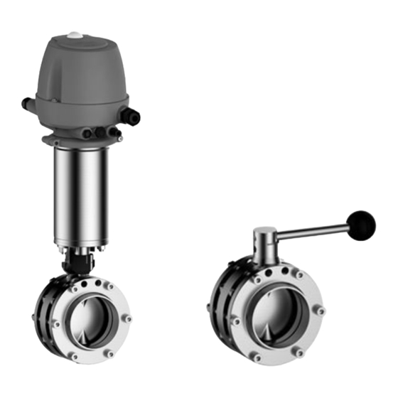
- Page 1 Hygienic valves GEA T-smart 7 butterfly valve Operating instruction (Translation from the original language) 430BAL009990EN_2...
- Page 2 EU Machinery Directive. This document is protected by copyright. All rights reserved. The document may not, in whole or in part, be copied, reproduced, translated or reduced to an electronic medium of machine-readable form without the express permission of GEA Tuchenhagen GmbH. LEGAL NOTICE Word marks ®...
-
Page 3: Table Of Contents
TABLE OF CONTENTS General Information Information on the Document 1.1.1 Binding Character of These Operating Instructions 1.1.2 Notes on the Illustrations 1.1.3 Symbols and Highlighting Manufacturer address Contact EU Declaration of Conformity for Machines Safety Intended use 2.1.1 Requirements for operation 2.1.2 Flow speed 2.1.3... - Page 4 12.2.1 General notes 12.2.2 Valve Actuator Disposal Parts list - Manual actuator for butterfly valve T-smart 7 Spare parts list - Pneumatic actuator Parts list - Butterfly valve body T-smart 7 Parts list - Butterfly valve 788 Dimension sheet - T-smart 7...
-
Page 5: General Information
General Information Information on the Document General Information Information on the Document The present Operating Instructions are part of the user information for the product. The Operating Instructions contain all the information you need to transport, install, commission, operate and carry out maintenance for the product. 1.1.1 Binding Character of These Operating Instructions These Operating Instructions contain the manufacturer's instructions to the... -
Page 6: Manufacturer Address
Second step in a sequence of operations. ® Result of the previous operation. ® The operation is complete, the goal has been achieved. Hint! Further useful information. Manufacturer address GEA Tuchenhagen GmbH Am Industriepark 2-10 21514 Büchen Contact Tel.:+49 4155 49-0 Fax:+49 4155 49-2035 flowcomponents@gea.com www.gea.com 430BAL009990EN_2 30.01.2018... -
Page 7: Eu Declaration Of Conformity For Machines
General Information EU Declaration of Conformity for Machines EU Declaration of Conformity for Machines in accordance with the EC Machinery Directive 2006/42/EC, Annex II 1. A GEA Tuchenhagen GmbH Manufacturer: Am Industriepark 2-10 21514 Büchen We declare under our sole responsibility that the machine... -
Page 8: Safety
The valve is a piece of pressure equipment (without safety function) as defined in the Pressure Equipment Directive: Directive 2014/68/EG. They are classified according to Annex II, article 4, section 3. In the event of any deviations, GEA Tuchenhagen GmbH will supply a specific Declaration of Conformity. -
Page 9: Operator's Duty Of Care
Safety Operator’s Duty of Care The operation of the component is not permitted if: • Persons or objects are in the danger zone. • Safety devices are not working or were removed. • Malfunctions have been detected on the component. •... -
Page 10: Subsequent Changes
EC Machinery Directive on your own. In general, only original spare parts supplied by GEA Tuchenhagen GmbH should be fitted. This ensures that the component is always operating properly and efficiently. -
Page 11: Electrical Equipment
Safety Supplementary Regulations • Substances harmful to the environment must be collected and stored in suitable containers. Clearly mark the containers. • Dispose of lubricants as hazardous waste. 2.4.3 Electrical Equipment For all work on electrical equipment, the following principles apply: •... -
Page 12: Safety Equipment
Safety Safety equipment • Personal suitability for the respective task. • Sufficient professional qualification for the respective task. • Received instruction about the functionality of the component. • Received instruction about operating sequences on the component. • Familiar with the safety devices and their function. •... -
Page 13: Residual Dangers
Earthing and short-circuiting. Cover or safeguard any adjacent live parts. Spring tension in the actuator Danger to life caused by compression spring in the actuator. Do not open the actuator but return it to GEA Tuchenhagen for proper disposal. 430BAL009990EN_2 30.01.2018... -
Page 14: Hazard Areas
Safety Hazard Areas Residual dangers on the valve and measures Danger Cause Measure Danger of injury Danger presented by moving or The operator must exercise caution and prudence. sharp-edged parts For all work: • Wear suitable work clothing. • Never operate the machine if the cover panels are not correctly fitted. - Page 15 Safety • If work on live parts cannot be avoided, call in a second person, who can operate the main switch in case of an emergency. 430BAL009990EN_2 30.01.2018...
-
Page 16: Description
Description Butterfly valve with control top Description Butterfly valve with control top Fig.4 Designation Pneumatic Actuator T.VIS control top Mounting bracket Butterfly valve body Butterfly valve without control top Fig.5 Designation Pneumatic Actuator Mounting bracket Butterfly valve body Electrical feedback (proximity switch in Optional the mounting bracket) 430BAL009990EN_2... -
Page 17: Intermediate Flange Design - Vv (788)
Description Intermediate flange design – VV (788) Intermediate flange design – VV (788) Fig.6 Butterfly valve design for matrix-piped systems. Manual actuator There are different construction designs for the manual actuator. Standard design manual actuator Fig.7 Designation Standard Electric feedback Scissor grip drive Fig.8 The scissor grip drive can position the shut-off disk in the predefined positions... - Page 18 Description Manual actuator Adjustable manual operation Fig.9 The lever on the adjustable hand drive can be continually adjusted in the range of 0° to 90°. 430BAL009990EN_2 30.01.2018...
-
Page 19: Functional Description
Description Functional description Functional description 3.5.1 Pneumatic Actuator The compressed air which enters above the piston causes a downwards movement of the piston and the disk of the butterfly valve opens or closes, depending on the definition of the resting position. When the air supply is shut off, the valve closes automatically as a result of the spring force. -
Page 20: Manual Actuator Type H
Description The visual position indication (O) can be recognized by the red marking. 3.5.4 Manual Actuator Type H Fig.12 To open or close the valve, release the hand lever (1) by gently pulling it out of the locking device and turning it by 90°. When the lever is released, it locks into place in the holes provided. -
Page 21: Transport And Storage
Transport and storage Storage conditions Transport and storage Storage conditions The valves, valve inserts or spare parts should be stored in a dry place, free of vibrations and dust, and protected from light. To avoid damage, leave the components in their original packaging if possible. If, during transport or storage, the valve is going to be exposed to temperatures ≤... -
Page 22: Technical Data
Type plate The type plate clearly identifies the valve. Fig.14 The type plate provides the following key data: Key data of the valve Type Butterfly valve T-smart 7 Serial Serial number Material AISI 304/FKM Control air pressure bar/psi min. 4.8/69.6 max. 8.0/116... - Page 23 Technical data Technical data Technical data: Ambient temperatures Designation Description - Control top type T.VIS M-15, A-15 -20 to +50 °C (-4 ... +122 °F) - Control top type T.VIS P-15 0 to +50 °C (-4 ... +122 °F) Product temperature and operating Depending on the sealing material temperature Technical data: Compressed air supply...
-
Page 24: Resistance Of Sealing Materials
Technical data Resistance of Sealing Materials Equipment: Proximity switches – actuator without T.VIS Operating voltage [V] 10...65 DC 20...25 AC Switching distance [mm] Max. continuous current >3...<100 >3...<100 [mA] Ambient temperature [°C] -25...+80 -25...+80 Protection class IP 67 IP 67 Resistance of Sealing Materials The resistance of sealing materials depends on the type and temperature of the medium conveyed. -
Page 25: Pipe Ends - General Table Of Measurements
Technical data Pipe ends - General table of measurements Sealing resistance table Sealing material (general operation temperature) Medium at permissible EPDM HNBR operating -40...+135°C* -10...+200 °C* -25...+140 °C* -50...+200 °C* temperature (-40...275°F*) (+14...+392°F*) (-13...+284°F*) (-58...+392 °F*) Fuels/ – hydrocarbons Product with a fat content up to Product with a fat content of more... -
Page 26: Tool
Technical data Tool Dimensions for Pipes in Inch OD Outside Outside Wall Inside Inch OD diameter acc. diameter thickness diameter to BS 4825 0.5" 12.7 1.65 0.75" 19.05 1.65 15.75 1" 25.4 1.65 22.1 1.5" 38.1 1.65 34.8 2" 50.8 1.65 47.5 2.5"... -
Page 27: Lubricants
Technical data Lubricants Lubricants Lubricants Material no. Rivolta F.L.G. MD-2 413-071 PARALIQ GTE 703 413-064 Grease BARRIERTA L 55/3 413-137 (only for seals VMQ) Weights TYPE GS Weight butterfly valve with actuator [kg] Size Pneumatic actuator Pneumatic actuator with Manual actuator without control top T.VIS control top DN 25, 1"... - Page 28 Technical data TYPE VV Weight butterfly valve with actuator [kg] Size Pneumatic actuator Pneumatic actuator with Manual actuator without control top T.VIS control top DN 40, 1.5" DN 50, 2" DN 65, 2.5" DN 80, 3" 10.4 DN 100, 4" 11.6 12.8 DN 125...
-
Page 29: Assembly And Installation
Assembly and installation Safety instructions Assembly and installation Safety instructions Hazardous situations during installation can be avoided by safety-conscious and proactive behaviour of the personnel. For installation, the following principles apply: • Only qualified personnel are allowed to set-up, install and commission the component. -
Page 30: Butterfly Valve With Intermediate Flange Design
Assembly and installation Butterfly Valve with Intermediate Flange Design Remove the complete actuator (A). To do so, unscrew the screws (1) from the bracket (K) and the butterfly valve body. Fig.15 Cut the pipe open at the point of installation. Weld the butterfly valve body in position in the pipe system, ensuring that the connection is free of stress and distortion. -
Page 31: Butterfly Valve With Screw Connection (G, K, C)
Assembly and installation Butterfly valve with screw connection (G, K, C) Weld the plain flanges in position in the pipe system, ensuring that the connection is free of stress and distortion. Use the TIG welding with pulse method. Screw the butterfly valve body to the plain flanges. ! Installation outer flange type VV: Arrange additional holes so that bracket (K) can be dismantled in assembled condition. -
Page 32: Air Requirement
Assembly and installation Electrical connections 6.6.1 Air Requirement The air requirement for the switching operations depends on the actuator type. Air requirement (dm stroke) dm at 1.01325 Actuator type Actuator Ø (mm) bar at 0°C in accordance with DIN 1343 BFV-7 83 88.9 0.325... -
Page 33: Electrical Connection With T.vis Control Top
Assembly and installation Electrical connections 6.7.1 Electrical connection with T.VIS control top Danger Live parts Electrical shock can result in serious personal injury or death. ► Only allow properly qualified staff to carry out work on the electrical equipment. ► Prior to establishing electrical connections check the maximum permissible operating voltage. - Page 34 Assembly and installation Hold the proximity switch and turn the cap nuts until a switching gap of max. 4 mm to the associated contact element is achieved. Tighten the cap nuts. ® Done 430BAL009990EN_2 30.01.2018...
-
Page 35: Start-Up
Start-up Safety instructions Start-up Safety instructions Initial commissioning For initial commissioning, the following principles apply: • Take protective measures against dangerous contact voltages in accordance with pertinent regulations. • The valve must be completely assembled and correctly adjusted. All screw connections must be securely tightened. -
Page 36: Operation And Control
Operation and control Safety instructions Operation and control Safety instructions Dangerous situations during operation can be avoided by safety-conscious and proactive behaviour of the personnel. For operation, the following principles apply: • Monitor the component during operation. • Safety devices must not be changed, removed or taken out of service. Check all safety devices at regular intervals. -
Page 37: Cleaning
Cleaning Cleaning Cleaning Cleaning All parts in contact with product must be cleaned at regular intervals. Always observe the safety data sheets issued by the cleaning agent manufacturers. Only use cleaning agents which do not cause damage to the seals and the inner parts of the valve. -
Page 38: Rinsing Operations
Cleaning Passivation 9.1.3 Rinsing operations The table lists the values for the duration and number of rinsing operations. Number of Medium Duration [s] rinsing Cleaning steps operations Beer 1...2 2...3 During every cleaning phase: Yeast 1...2 2...3 Prerinse Fruit juice 2...5 Hot caustic Milk... -
Page 39: Maintenance
Maintenance Safety instructions Maintenance 10.1 Safety instructions Maintenance and repair Before carrying out maintenance and repair work on the component's electrical equipment, perform the following steps in accordance with the "5 safety rules": • Isolate from the power supply • Take appropriate measures to prevent switch on •... -
Page 40: Inspections
Maintenance Inspections • Disconnect all power and utility lines. • Markings, e.g. on lines, must not be removed. • Do not climb on the component. Use suitable access aids and working platforms. • Mark the lines (if unmarked) prior to disassembly to ensure they are not confused when re-assembling. -
Page 41: Maintenance Intervals
Maintenance Maintenance intervals ® Done 10.3 Maintenance intervals To ensure the highest operational reliability, all wearing parts should be replaced at longer intervals. The actual maintenance intervals can only be determined by the user since they depend on the operating conditions, for instance: •... -
Page 42: Removing The T.vis M-15 Control Top
Maintenance Disassembling the Valve 10.5.1 Removing the T.VIS M-15 Control Top Fig.18 Prerequisite: • The pneumatic and electrical connections on the plant side can remain on the control top. Notice! The permanent magnet on the switch bar is fragile. Damage to the permanent magnet. ►... -
Page 43: Removing Control Top Type T.vis P-15 And
Maintenance Disassembling the Valve 10.5.2 Removing control top type T.VIS P-15 and A-15 Fig.19 Prerequisite: • The pneumatic and electrical connections on the plant side can remain on the control top. Notice! The permanent magnet on the switch bar is fragile. Damage to the permanent magnet. -
Page 44: Removing The Proximity Switch - Actuator Without T.vis
Maintenance Disassembling the Valve 10.5.3 Removing the proximity switch – actuator without T.VIS Fig.20 Carry out the following steps: Unscrew the hexagon nuts (2) on the proximity switches (1). Remove the proximity switches (1). ® Done 10.5.4 Intermediate flange design type VV – removing the valve Fig.21 Carry out the following steps: Undo the screw connections (3). -
Page 45: Dismantling The Actuator Parts
Maintenance Disassembling the Valve Fig.22 Carry out the following steps: Undo the screw connections (1). Lift off the actuator (A). ® Done Hint! The red position indication marker (2) is aligned with the hole (B) in the disk so that it indicates the position of the disk in the valve. 10.5.6 Dismantling the Actuator Parts Fig.23... -
Page 46: Removing The Manual Actuator H
Maintenance Disassembling the Valve Remove the position indicator (2) together with the bracket (6). Unscrew the elbow screw-in plug connection (5). ® Done 10.5.7 Removing the manual actuator H Fig.24 Carry out the following steps: Use an a/f 4 hex socket screwdriver to unscrew the locking screw (2) until it is flush with the bushing. - Page 47 Maintenance Disassembling the Valve Type SS Type VV Fig.26 Fig.25 Removing the Flanges Carry out the following steps: Undo the screw connections (3). Fig.27 Pull the butterfly valve body apart. Remove the stopper (7). 430BAL009990EN_2 30.01.2018...
- Page 48 Maintenance Disassembling the Valve Fig.28 ® The stopper protects the plain bearing from soiling. Take out the shut-off disk (4) with the seal (6). ® Done Removing the Seal Carry out the following steps: Pull off the plain bearings (5). Turn the seal (6) until it is positioned at a 90°...
-
Page 49: Maintenance
Maintenance Maintenance Fig.30 Remove the O-ring (8). ® Done ® The disk seal is now completely removed. 10.6 Maintenance 10.6.1 Cleaning the Valve Notice! Damage to the valve Damage to the valve can result in a malfunction. ► Observe the safety information sheets issued by the detergent manufacturers! ►... -
Page 50: Lubricating Seals And Threads
Maintenance Maintenance Fig.31 ® Done 10.6.2 Lubricating Seals and Threads Caution! Damage to seals and threads Damage to seals and threads can result in a malfunction. ► Ensure that an adequate film of lubricant is applied. No grease residues must be visible once the valve has been assembled completely. ►... -
Page 51: Installation
PARALIQ GTE 703 can be ordered under the material no. 413-064, Rivolta F.L.G. MD-2 under the material no. 413-071 and grease BARRIERTA L 55/3* under the material no. 413-137 from GEA Tuchenhagen. Using other types of grease can result in malfunctions or in premature seal failure. -
Page 52: Torques For The Clamps And Clamp Connections
Maintenance • When the actuator is mounted, the disk must be in the correct position: for resting position closed: disk closed for resting position open: Disk at 90° position. • Installation outer flange type VV: Arrange additional holes so that bracket can be dismantled in assembled condition. -
Page 53: Alarms
Alarms Malfunctions and remedies Alarms 11.1 Malfunctions and remedies In the event of malfunctions immediately deactivate the valve and secure it against inadvertent reactivation. Malfunctions may only be remedied by qualified staff, who must observe the safety instructions. Malfunction Cause Remedy Actuator does not work Air hoses clogged or... -
Page 54: Decommissioning
► Never open the actuator. ► GEA Tuchenhagen accepts unopened actuators and arranges for proper disposal free of charge. Carry out the following steps: Remove the actuator. Pack the actuator safely and send it to GEA Tuchenhagen GmbH. ® Done 430BAL009990EN_2 30.01.2018... -
Page 55: Parts List - Manual Actuator For Butterfly Valve T-Smart
Parts list - Manual actuator for butterfly valve T-smart 7 Parts list - Manual actuator for butterfly valve T-smart 7 Fig.33: Manual actuator for BFV Fig.34: Installation variants for proximity switches 430BAL009990EN_2 30.01.2018... - Page 56 Parts list - Manual actuator for butterfly valve T-smart 7 Item Designation Nominal width Nominal width Nominal width DN 15 - DN 65 DN 80 / 3" OD DN 125 0.5" OD - 2.5" OD DN 100 / 4" OD...
-
Page 57: Spare Parts List - Pneumatic Actuator
Spare parts list - Pneumatic actuator Spare parts list - Pneumatic actuator for butterfly valve T-smart 7 Fig.35 430BAL009990EN_2 30.01.2018... - Page 58 Spare parts list - Pneumatic actuator Fig.36 430BAL009990EN_2 30.01.2018...
- Page 59 Spare parts list - Pneumatic actuator Item Designation Material DN 25 DN 40 DN 50 DN 65 1" OD 1.5" OD 2" OD 2.5" OD Actuator BFV-7 / NC/NO/ cpl. 224-001503 224-001503 224-001503 224-001503 A (opt.) Actuator BFV-7 / AA/ cpl. (air/air) 224-001504 224-001504 224-001504...
- Page 60 Spare parts list - Pneumatic actuator Item Designation Material DN 80 DN 100 DN 125 DN 150 3" OD 4" OD Actuator BFV-7 / NC/NO/ cpl. 224-001505 224-001660 224-001509 224-001509 A (opt.) Actuator BFV-7 / AA/ cpl. (air/air) 224-001506 224-001506 224-001508 224-001508 Console BFV-7...
-
Page 61: Parts List - Butterfly Valve Body T-Smart
Parts list - Butterfly valve body T-smart 7 Parts list - Butterfly valve body T-smart 7 (two-piece flange versions) Fig.37: Butterfly valve body T-smart 7 Fig.38: Two-piece flange versions 430BAL009990EN_2 30.01.2018... - Page 62 Parts list - Butterfly valve body T-smart 7 Item Designation Material DN 15 DN 20 DN 25 DN 40 DN 50 Butterfly valve 304 / EPDM 224-905.20 224-905.21 224-905.22 224-905.24 224-905.25 T-smart 711 (SS) cpl. 316L / EPDM 224-905.01 224-905.02 224-905.03...
- Page 63 Parts list - Butterfly valve body T-smart 7 Item Designation Material DN 65 DN 80 DN 100 DN 125 DN 150 Butterfly valve 304 / EPDM 224-905.26 224-905.27 224-905.28 224-905.29 224-905.30 T-smart 711 (SS) cpl. 316L / EPDM 224-905.07 224-905.08 224-905.09...
- Page 64 Parts list - Butterfly valve body T-smart 7 Item Designation Material 0.5" OD 0.75" OD 1" OD 1.5" OD Butterfly valve 304 / EPDM 224-905.31 224-905.21 224-905.33 224-905.34 T-smart 711 (SS) cpl. 316L / EPDM 224-905.12 224-905.01 224-905.14 224-905.15 304 / FKM 224-915.31...
- Page 65 Parts list - Butterfly valve body T-smart 7 Item Designation Material 2" OD 2.5" OD 3" OD 4" OD Butterfly valve 304 / EPDM 224-905.35 224-905.36 224-905.37 224-905.38 T-smart 711 (SS) cpl. 316L / EPDM 224-905.16 224-905.17 224-905.18 224-905.19 304 / FKM 224-915.35...
- Page 66 Parts list - Butterfly valve body T-smart 7 Item Designation Material DN 15 DN 20 DN 25 DN 40 DN 50 Welded flange 224-000899 224-000900 224-000901 224-000902 224-000903 316L 224-000705 224-000706 224-000707 224-000708 224-000709 Threaded flange DIN 224-000945 224-000946 224-000947...
- Page 67 Parts list - Butterfly valve body T-smart 7 Item Designation Material 0.5" OD 0.75" OD 1" OD 1.5" OD Welded flange 224-000915 224-000899 224-000909 224-000910 316L 224-000816 224-000705 224-000715 224-000716 Threaded flange DIN 224-000978 224-000979 316L 224-000729 224-000730 Clamp flange...
- Page 68 Parts list - Butterfly valve body T-smart 7 Item Designation Material DN 25 DN 40 DN 50 DN 65 DN 80 DN 100 DN 125 DN 150 Sealing ring G for EPDM 928-338 928-340 928-341 928-342 928-343 928-344 928-349 928-368...
- Page 69 Parts list - Butterfly valve body T-smart 7 Designation Material DN 25 DN 40 DN 50 DN 65 Butterfly valve T-smart 733 304 / EPDM 224-911.39 224-911.40 224-911.41 224-911.42 (CC) cpl. 316L / EPDM 224-911.33 224-911.34 224-911.35 224-911.36 304 / FKM 224-921.39...
- Page 70 Parts list - Butterfly valve body T-smart 7 Designation Material DN 80 DN 100 DN 125 DN 150 Butterfly valve T-smart 733 304 / EPDM 224-911.43 224-911.44 (CC) cpl. 316L / EPDM 224-911.37 224-911.38 304 / FKM 224-921.43 224-921.44 316L / FKM 224-921.37...
- Page 71 Parts list - Butterfly valve body T-smart 7 Designation Material 1" OD 1.5" OD 2" OD Butterfly valve T-smart 721 304 / EPDM 224-947.37 224-947.38 224-947.39 (GS-RJT) cpl. 316L / EPDM 224-947.13 224-947.14 224-947.15 304 / FKM 224-951.37 224-951.38 224-951.39 316L / FKM 224-951.13...
- Page 72 Parts list - Butterfly valve body T-smart 7 Designation Material 1" OD 1.5" OD 2" OD Butterfly valve T-smart 722 304 / EPDM on request on request on request (GG-IDF) cpl. 316L / EPDM on request on request on request...
- Page 73 Parts list - Butterfly valve body T-smart 7 Designation Material 1" OD 1.5" OD 2" OD Butterfly valve T-smart 733 304 / EPDM 224-911.11 224-911.12 224-911.13 (CC) cpl. 316L / EPDM 224-911.03 224-911.04 224-911.05 304 / FKM 224-921.11 224-921.12 224-921.13 316L / FKM 224-921.03...
- Page 74 Parts list - Butterfly valve body T-smart 7 Designation Material 2.5" OD 3" OD 4" OD Butterfly valve T-smart 721 304 / EPDM 224-947.40 224-947.41 224-947.42 (GS-RJT) cpl. 316L / EPDM 224-947.16 224-947.17 224-947.18 304 / FKM 224-951.40 224-951.41 224-951.42 316L / FKM 224-951.16...
- Page 75 Parts list - Butterfly valve body T-smart 7 Designation Material 2.5" OD 3" OD 4" OD Butterfly valve T-smart 722 304 / EPDM on request on request on request (GG-IDF) cpl. 316L / EPDM on request on request on request...
- Page 76 Parts list - Butterfly valve body T-smart 7 Designation Material 2.5" OD 3" OD 4" OD Butterfly valve T-smart 304 / EPDM 224-911.14 224-911.15 224-911.16 733 (CC) cpl. 316L / EPDM 224-911.06 224-911.07 224-911.08 304 / FKM 224-921.14 224-921.15 224-921.16 316L / FKM 224-921.06...
-
Page 77: Parts List - Butterfly Valve 788
Parts list - Butterfly valve 788 Parts list - Butterfly valve 788 (Intermediate flange version VV) Fig.39 430BAL009990EN_2 30.01.2018... - Page 78 Parts list - Butterfly valve 788 Item Designation Material DN 15 DN 20 DN 25 DN 40 Butterfly valve 304 / EPDM 224-906.20 224-906.21 224-906.22 224-906.24 T-smart 788 (VV) complete 316L / EPDM 224-906.01 224-906.02 224-906.03 224-906.05 304 / FKM 224-916.20 224-916.21 224-916.22...
- Page 79 Parts list - Butterfly valve 788 Item Designation Material DN 50 DN 65 DN 80 Butterfly valve 304 / EPDM 224-906.25 224-906.26 224-906.27 T-smart 788 (VV) complete 316L / EPDM 224-906.06 224-906.07 224-906.08 304 / FKM 224-916.25 224-916.26 224-916.27 316L / FKM 224-916.06 224-916.07 224-916.08...
- Page 80 Parts list - Butterfly valve 788 Item Designation Material DN 100 DN 125 DN 150 Butterfly valve 304 / EPDM 224-906.28 224-906.29 224-906.30 T-smart 788 (VV) complete 316L / EPDM 224-906.09 224-906.10 224-906.11 304 / FKM 224-916.28 224-916.29 224-916.30 316L / FKM 224-916.09 224-916.10 224-916.11...
- Page 81 Parts list - Butterfly valve 788 Item Designation Material 0.5" OD 0.75" OD 1" OD 1.5" OD Butterfly valve 304 / EPDM 224-906.31 224-906.20 224-906.33 224-906.34 T-smart 788 (VV) complete 316L / EPDM 224-906.12 224-906.01 224-906.14 224-906.15 304 / FKM 224-916.31 224-916.20 224-916.33...
- Page 82 Parts list - Butterfly valve 788 Item Designation Material 2" OD 2.5" OD 3" OD 4" OD Butterfly valve 304 / EPDM 224-906.35 224-906.36 224-906.37 224-906.38 T-smart 788 (VV) complete 316L / EPDM 224-906.16 224-906.17 224-906.18 224-906.19 304 / FKM 224-916.35 224-916.36 224-916.37...
-
Page 83: Dimension Sheet - T-Smart
Dimension sheet - T-smart 7 Dimension sheet - T-smart 7 Fig.40 Fig.41 430BAL009990EN_2 30.01.2018... - Page 84 Dimension sheet - T-smart 7 DN 15 DN 20 DN 25 DN 40 DN 50 Item Designation Dimension 0.5" OD 0.75" OD 1" OD 1.5" OD 2" OD Pneumatic actuator with T.VIS Ø B / DN control top, installation dimension X Ø...
- Page 85 Dimension sheet - T-smart 7 DN 15 DN 20 DN 25 DN 40 DN 50 Item Designation Dimension 0.5" OD 0.75" OD 1" OD 1.5" OD 2" OD Threaded flange RJT C5 OD G5 OD 45.7x1/8 58.4x1/8 72.7x1/6 Internal Ø DN Internal Ø...
- Page 86 Dimension sheet - T-smart 7 DN 65 DN 80 DN 100 DN 125 DN 150 Item Designation Dimension 2.5" OD 3" OD 4" OD Pneumatic actuator with T.VIS Ø B / DN control top, installation dimension X Ø B / OD D / actuator Ø...
- Page 87 Dimension sheet - T-smart 7 DN 65 DN 80 DN 100 DN 125 DN 150 Item Designation Dimension 2.5" OD 3" OD 4" OD Internal Ø OD 60.3 97.6 Threaded flange RJT C5 OD G5 OD 85.4x1/6 98.1x1/6 123.5x1/6 Internal Ø DN Internal Ø...
-
Page 88: Dimension Sheet - Butterfly Valve T-Smart 7 Vv
Dimension sheet - Butterfly valve T-smart 7 VV Dimension sheet - Butterfly valve T-smart 7 VV Fig.42 Fig.43 430BAL009990EN_2 30.01.2018... - Page 89 Dimension sheet - Butterfly valve T-smart 7 VV DN 15 DN 20 DN 25 DN 40 DN 50 Item Designation Dimension 0.5" OD 0.75" OD 1" OD 1.5" OD 2" OD Pneumatic actuator with T.VIS Ø B / DN control top, installation dimension X Ø...
- Page 90 Dimension sheet - Butterfly valve T-smart 7 VV DN 65 DN 80 DN 100 DN 125 DN 150 Item Designation Dimension 2.5" OD 3" OD 4" OD Pneumatic actuator with T.VIS Ø B / DN control top, installation dimension X Ø...
-
Page 91: Dimension Sheet - Butterfly Valve T-Smart 7 - Flanges
Dimension sheet - Butterfly valve T-smart 7 - flanges Dimension sheet - Butterfly valve T-smart 7 - flanges Fig.44: Dimension drawing BFV-7 seals 430BAL009990EN_2 30.01.2018... - Page 92 Dimension sheet - Butterfly valve T-smart 7 - flanges Nominal width Material Material DN 15 EPDM 224-170.61 224-170.75 22.2 36.0 20.5 HNBR 224-170.89 224-173.05 DN 20 EPDM 224-170.61 224-170.75 22.2 36.0 20.5 HNBR 224-170.89 224-173.05 DN 25 EPDM 224-170.67 224-170.81 26.0...
- Page 93 Dimension sheet - Butterfly valve T-smart 7 - flanges Nominal width Material Material EPDM 224-170.61 224-170.75 0.5" OD 22.2 36.0 20.5 HNBR 224-170.89 224-173.05 EPDM 224-170.61 224-170.75 0.75" OD 22.2 36.0 20.5 HNBR 224-170.89 224-173.05 EPDM 224-170.61 224-170.75 1" OD 22.2...
-
Page 94: Appendix
Appendix Lists Appendix 20.1 Lists 20.1.1 Abbreviations and terms Abbreviation Explanation British Standard Unit of measurement of pressure [bar] All pressure data expressed in [bar/psi] is assumed to be gauge pressure [barg/psig] unless explicitly specified otherwise. approx. approximately °C Unit of measurement of temperature [degree Celsius] Unit of measurement of volume [cubic decimetre] Standard volume (standard litre) DIN nominal width... - Page 95 Appendix Abbreviation Explanation Metric Unit of measurement of work [newton metre] Specification of torque 1 Nm = 0.737 lbft Pound-Force (lb) + Feet (ft) Polyamide PE-LD Low-density polyethylene Polytetrafluoroethylene America measurement for pressure [Pound-forse per square inch] All pressure data expressed in [bar/psi] is assumed to be gauge pressure [barg/psig] unless explicitly specified otherwise.
Need help?
Do you have a question about the T-smart 7 and is the answer not in the manual?
Questions and answers