
Related Manuals for GEA ECOVENT N/W


Summary of Contents for GEA ECOVENT N/W
- Page 1 Operating Instructions ® ECOVENT Valve N/W and N.M DN 10/15 Edition 2014-07-04 English...
- Page 2 These operating instructions are protected by copyright. All rights reserved. The docu- ment may not, in whole or in part, be copied, reproduced, translated or reduced to an electronic medium of machine-readable form without the express permission of GEA Tuchenhagen GmbH.
-
Page 3: Table Of Contents
Table of Contents Notes for the Reader ............................5 Binding Character of These Operating Instructions ..................5 Notes on the Illustrations ..........................5 Symbols and Highlighting ..........................6 Abbreviations and Terms ..........................7 Safety ................................9 Safety Note ............................... 9 Operator's Duties .............................. - Page 4 Electrical Connections............................. 27 Commissioning..............................27 Malfunctions ..............................28 Maintenance ..............................29 Inspections ..............................29 • Product Contact Seals ..........................29 • Pneumatic Connections ..........................29 • Electrical Connections ..........................29 Maintenance Intervals ............................. 30 Removing the Valve ............................30 Disassembling Valve N ........................... 31 •...
-
Page 5: Notes For The Reader
Notes for the Reader Notes on the Illustrations Notes for the Reader The present Operating Instructions are part of the user information for the valve. The Operating Instructions contain all the information you need to transport, install, commis- sion, operate and carry out maintenance for the valve. Binding Character of These Operating Instructions These Operating Instructions contain the manufacturer's instructions for the owner of the valve and for all persons who work on or use the valve regarding the procedures to... -
Page 6: Symbols And Highlighting
Notes for the Reader Symbols and Highlighting Symbols and Highlighting In these Operating Instructions, important information is highlighted by symbols or special formatting. The following examples illustrate the most important types of high- lighting. DANGER Warning: Fatal Injuries. Failure to observe the warning can cause serious damage to health, or even death. ... -
Page 7: Abbreviations And Terms
Notes for the Reader Abbreviations and Terms NOTE Further useful information. Abbreviations and Terms Abbreviation Explanation Indicates the size of spanners width across flats approx. approximately British Standard Unit of measurement of pressure [bar] All pressure ratings [bar/psi] stand for over pressure [bar /psi if this is not explicitly described differently. - Page 8 Notes for the Reader Abbreviations and Terms Abbreviation Explanation Unit of measurement of force [kilonewton] Unit of measurement of volume [litre] max. maximum Unit of measurement of length [millimetre] m Unit of measurement of length [micrometre] metric Unit of measurement of work [newton metre] 1 Nm = 0.737 lbft NIT OF TORQUE Pound-Force (lb) + Feet (ft)
-
Page 9: Safety
Safety Operator's Duties Safety Safety Note The valve is operationally reliable. It was built according to state-of-the art standards. Nevertheless, the valve can pose dangers, especially if • the valve is not used in accordance with its intended use, • the valve is not used correctly, •... -
Page 10: Qualification Of Staff
Safety Qualification of Staff Qualification of Staff This section contains information about the qualifications that staff working on the valve must have. Operating and maintenance staff must • have the necessary qualification to carry out their tasks, • be instructed with regard to possible dangers, •... -
Page 11: Supplementary Regulations
Safety Supplementary Regulations User groups (Cont.) Staff Qualifications Maintenance staff Adequate instruction as well as sound knowledge of the design and function of the valve. Sound knowledge in the following areas: • Mechanical equipment • Electrical equipment • Pneumatic system Authorization with regard to safety engineering standards to carry out the following tasks: •... -
Page 12: Instructions For The Safe Operation
Safety Instructions for the Safe Operation Instructions for the Safe Operation Dangerous situations during the operation can be avoided by safety-conscious and proactive behaviour of the staff. General Principles To ensure the safe operation of the valve the following principles apply: •... -
Page 13: Commissioning/Setup Mode
Safety Instructions for the Safe Operation Commissioning/Setup Mode For commissioning, the following principles apply: • Take protective measures against dangerous contact voltages in accordance with pertinent regulations. • The valve must be completely assembled and correctly adjusted. All screw connec- tions must be securely tightened. -
Page 14: Shutting Down
Safety Instructions for the Safe Operation Shutting Down For shutting down, the following principles apply: • Switch off the compressed air. • Switch off the valve via the main switch. • Padlock the main switch (if fitted) in the off position to prevent it from being switched back on. -
Page 15: Disassembly
Safety Instructions for the Safe Operation Disassembly For disassembly, the following principles apply: • Only allow qualified staff to disassemble the valve. • Before starting disassembly, the valve must be switched off and secured against being switched back on. Work may only be started once any residual energy has been discharged. -
Page 16: Signage
Safety Signage Signage Dangerous points on the valve are indicated by warning signs, prohibition signs and mandatory signs. The signs and notes on the valve must always be legible. Any illegible signs must be replaced immediately. Signs on the valve Sign Meaning General hazard warning... -
Page 17: Residual Risk
Safety Residual Risk Residual Risk Hazard Areas Please observe the following notes: • In the event of malfunctions, shut down the valve (disconnect from the power and air supply) and secure it against being used. • Never reach into the lantern (9) or the valve housing when the valve is switching. Fingers can be crushed or cut off. -
Page 18: Residual Dangers
Cover or safeguard any adjacent live parts. Spring tension in the actuator Danger to life caused by compression spring in the actu- ator. Do not open the actuator but return it to GEA Tuchen- hagen for proper disposal. Danger of injury Danger presented by moving or The operator must exercise caution and prudence. -
Page 19: Declaration Of Incorporation
Safety Residual Risk Declaration of Incorporation Declaration of Incorporation in accordance with the EC Machinery Directive 2006/42/EC We herewith declare that this consignment contains the subsequently identified – but incomplete – machine and that putting into service is not permitted until it has been estab- lished that the machinery into which this machine is to be incorporated is in conformity with the provisions of the EC Machinery Directive. -
Page 20: Intended Purpose
The valves type N and W are pressure equipment (without safety function) in the sense of the pressure equipment directive: Directive 97/23/EC. They are classified according to Annex II, article 3, section 3. In the event of any deviations, GEA Tuchenhagen GmbH will supply a special Declaration of Conformity. -
Page 21: Improper Operating Conditions
EC Machinery Direc- tive on your own. In general, only original spare parts supplied by GEA Tuchenhagen GmbH should be fitted. This ensures the reliable and economical operation of the valve. -
Page 22: Transport And Storage
Transport and Storage Storage Transport and Storage Scope of Supply On receipt of the valve check whether • the details on the type plate correspond to the data in the order and delivery docu- ments, • the equipment is complete and all components are in good order. Transport For transport, the following principles apply: •... -
Page 23: Design
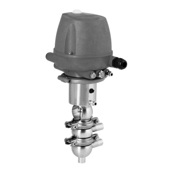
Design Design Designation T.VIS control module Actuator Switch bar Lantern Valve disk Housing Vent screw Air connection... -
Page 24: Installation And Commissioning
Installation and Commissioning Valve with Detachable Pipe Connection Elements Installation and Commissioning Notes on Installation The valve can be installed in any position. However, care must be taken to ensure that the valve housing and the pipe system can drain properly. To prevent damage, make sure that •... -
Page 25: Valve With Welding Ends
Installation and Commissioning Valve with Welding Ends Valve with Welding Ends This section describes the welding procedure for the valve. WARNING Spring tension in the valve Danger of injury when opening the clips (43) as the released spring pretension will suddenly lift the actuator. -
Page 26: Pneumatic Connections
Installation and Commissioning Pneumatic Connections Pneumatic Connections Air requirement Actuator type Actuator diam- Air pressure Air pressure Air requirement (dm /stroke) eter (mm) (bar) (bar) at 1.01325 bar max. min. at 0°C as per DIN 1343 60/4 0.03 Establishing the hose connection To ensure reliable operation, the compressed air hoses must be cut exactly square. -
Page 27: Electrical Connections
Installation and Commissioning Commissioning Electrical Connections DANGER Live parts Electrical shock can result in serious personal injury or death. Only allow properly qualified staff to carry out work on the electrical equipment. Prior to establishing electrical connections check the maximum permissible oper- ating voltage. -
Page 28: Malfunctions
Malfunctions Malfunctions In the event of malfunctions immediately deactivate the valve and secure it against inad- vertent reactivation. Malfunctions may only be remedied by qualified staff, who must observe the safety instructions. Malfunction Cause Remedy Valve does not work Fault in the Check the system configura- tion control system... -
Page 29: Maintenance
Maintenance Inspections Maintenance Inspections Between the maintenance periods, the valves must be checked for leakage and proper function. Product Contact Seals Carry out the following steps: Regularly check: – Stem seal between upper housing and lantern – V-ring in the valve disks –... -
Page 30: Maintenance Intervals
Maintenance Removing the Valve Maintenance Intervals To ensure the highest operational reliability of the valves, all wearing parts should be replaced at longer intervals. The actual maintenance intervals can only be determined by the user since they depend on the operating conditions, for instance: •... -
Page 31: Disassembling Valve N
Maintenance Disassembling Valve N Disassembling Valve N Removing the Control Module No solenoid valve must be actuated electrically or manually. Requirement The pneumatic and electrical connections on the plant side can remain on the control module. IMPORTANT NOTE The permanent magnet on the switch bar (1) is fragile. -
Page 32: Removing The Valve Insert
Maintenance Disassembling Valve N Removing the Valve Insert Spring closing valve WARNING Spring tension in the valve Danger of injury when opening the clips (43) as the released spring pretension will suddenly lift the actuator. Therefore, release the spring tension before detaching the clips by pressurizing the actuator with compressed air at max. -
Page 33: Dismantling Individual Parts
Maintenance Disassembling Valve N Spring opening valve IMPORTANT NOTE The valve disk is a sensitive component. Damage to the valve disk Do not set the valve insert down on the valve disk. Lay the valve insert down. Carry out the following steps: Depressurize the actuator via (61). -
Page 34: Converting The Actuator
Maintenance Disassembling Valve W Clamp the actuator into a vice and screw out the lantern (9) from the actuator using a bar or pipe (d ≤ 42). Unscrew the mounting base (198) using a face spanner. All seals are freely accessible ... -
Page 35: Removing The Valve Insert
Maintenance Disassembling Valve W Pull the control module (5) upwards to remove. The feedback signal to the higher-level control system is interrupted. Removing the Valve Insert Spring closing valve WARNING Spring tension in the valve Danger of injury when opening the clips (43) as the released spring pretension will suddenly lift the actuator. -
Page 36: Dismantling Individual Parts
Maintenance Disassembling Valve W Spring opening valve IMPORTANT NOTE The valve disk is a sensitive component. Damage to the valve disk Do not set the valve insert down on the valve disk. Lay the valve insert down. Carry out the following steps: Depressurize the actuator via (61). -
Page 37: Converting The Actuator
Maintenance Maintenance Use an open-end spanner on the flat to hold the adapter (141) and unscrew the switch bar (139). Clamp the actuator into a vice and screw out the lantern (9) from the actuator using a bar or pipe (d ≤ 42). Unscrew the mounting base (198) using a face spanner. -
Page 38: Replacing Seals
Maintenance Maintenance IMPORTANT NOTE The shaft of the valve disk (15) and the V-ring groove (A) are precision areas. Damage to these parts can result in malfunctions. Handle the valve with care! IMPORTANT NOTE Damage to the valve Damage to the valve can result in a malfunction. ... - Page 39 Maintenance Maintenance Use the insertion tool to fit the V-ring (see illustration). Requirement Insert V-rings without grease. To facilitate fitting V-rings use water (with a drop of washing-up liquid to remove the surface tension). In order that no rust is transferred, the washing-up liquid solution must be made up in a ceramic, plastic, or stainless steel container.
-
Page 40: Lubricating Seals And Threads
They have the NSF- H1 (USDA H1) registration. PARALIQ GTE 703 can be ordered from GEA Tuchenhagen under part no. 413-064, and Rivolta F.L.G. MD-2 can be ordered under part no. 413- 071. -
Page 41: Assembly
A Manufacturer's Declaration for these products can be obtained from GEA Tuchenhagen if required. A thin film of grease is required on the seals to ensure the proper function of the fittings. It reduces friction and extends the service life of the seals. -
Page 42: Valve Actuator Disposal
GEA Tuchenhagen accepts unopened actuators and arranges for proper disposal free of charge. Carry out the following steps: Remove the actuator. Safely pack the actuator and send it to GEA Tuchenhagen GmbH. ® Operating Instructions · ECOVENT Valve N/W and N.M DN 10/15... -
Page 43: Technical Data
Technical Data Technical Data Technical Data Type Plate The type plate clearly identifies the valve. Type plate of the valve The type plate provides the following key data: Key data of the valve Type Valve N/W and N.M DN 10/15 Serial Serial number Material... - Page 44 Technical Data Technical Data Technical data: Ambient temperatures Designation Description - Valve 0 to 60 °C, standard < 0 °C: use control air with a low dew point. Protect valve stems against freezing. - Proximity switch -20 to +80 °C - Control module type T.VIS M-1, A-8 -20 to +60 °C Control module type T.VIS P-20...
-
Page 45: Resistance Of Sealing Materials
Technical Data Resistance of Sealing Materials Resistance of Sealing Materials The resistance of sealing materials depends on the type and temperature of the medium conveyed. The exposure time can adversely affect the service life of the seals. The sealing materials comply with the regulations of FDA 21 CFR 177.2600 or FDA 21 CFR 177.1550. -
Page 46: Tools
Technical Data Lubricants Tools Tools Part no. Hose cutter 407-065 V-ring insertion tool 229-109.88 Hex key a/f 5 Square socket wrench a/f 10 Lubricants Lubricants Part no. Rivolta F.L.G. MD-2 413-071 PARALIQ GTE 703 413-064 ® Operating Instructions · ECOVENT Valve N/W and N.M DN 10/15 Edition 2014-07-04... -
Page 47: Spare Parts Lists
Set of seals EPDM 221-489.32 221-489.33 Sealing ring EPDM 924-255 924-297 Bearing PTFE/carbon 935-037 Bearing, 3A SUSTA-PVDF 935-097 GEA Mechanical Equipment GEA Tuchenhagen GmbH Am Industriepark 2-10, D-21514 Büchen, Germany Telephone +49 4155 49-0, Telefax +49 4155 49-2423 sales.geatuchenhagen@gea.com, http://www.tuchenhagen.com... - Page 48 1.4435 221-194.04 Housing W1/DN10 1.4435 221-305.03 Housing W2/DN10 1.4435 221-306.03 Housing W1/DN15 1.4435 221-305.04 Housing W2/DN15 1.4435 221-306.04 GEA Mechanical Equipment GEA Tuchenhagen GmbH Am Industriepark 2-10, D-21514 Büchen, Germany Telephone +49 4155 49-0, Telefax +49 4155 49-2423 sales.geatuchenhagen@gea.com, http://www.tuchenhagen.com...
- Page 49 Control module, T.VIS P-20 See spare parts list for control module T.VIS P-20 Items 1, 5, 6, 29, 60, 98, 101 and 129 are included in the sealing set. GEA Mechanical Equipment GEA Tuchenhagen GmbH Am Industriepark 2-10, D-21514 Büchen, Germany Telephone +49 4155 49-0, Telefax +49 4155 49-2423 sales.geatuchenhagen@gea.com, http://www.tuchenhagen.com...
- Page 50 Shut-Off Valve Type N_ECO and N.M DN 10/15 Spare_parts_lists.fm Shut-Off Valve Type N_ECO and N.M DN 10/15 Shut-Off Valve Type N_ECO DN 10/15, housing combination GEA Mechanical Equipment GEA Tuchenhagen GmbH Am Industriepark 2-10, D-21514 Büchen, Germany Telephone +49 4155 49-0, Telefax +49 4155 49-2423...
- Page 51 221-482.10 221-482.10 Adapter, SHO 1.4301 221-561.01 221-561.01 Mounting base, T.VIS compl. 221-589.32 221-589.32 Plain bearing IGLIDUR-G 704-041 704-041 GEA Mechanical Equipment GEA Tuchenhagen GmbH Am Industriepark 2-10, D-21514 Büchen, Germany Telephone +49 4155 49-0, Telefax +49 4155 49-2423 sales.geatuchenhagen@gea.com, http://www.tuchenhagen.com...
- Page 52 See spare parts list for control module T.VIS P-20 *Items 1, 5, 6, 7, 29, 60, 98, 101 and 129 are included in the sealing set. GEA Mechanical Equipment GEA Tuchenhagen GmbH Am Industriepark 2-10, D-21514 Büchen, Germany Telephone +49 4155 49-0, Telefax +49 4155 49-2423...
- Page 53 Manual Actuator – ECOVENT® Shuttle Valve W_ECO DN10/15 Manual Actuator – ECOVENT® Shut off Valve N_ECO DN10/15 Manual Actuator – ECOVENT® Shuttle Valve W_ECO DN10/15 GEA Mechanical Equipment GEA Tuchenhagen GmbH Am Industriepark 2-10, D-21514 Büchen, Germany Telephone +49 4155 49-0, Telefax +49 4155 49-2423...
- Page 54 Handwheel NH PPH 4150 221-342.03 Spindle NH 1.4301 221-342.04 Spacer NH 1.4301 221-342.05 Rod guide ring Turcite-B10 935-052 GEA Mechanical Equipment GEA Tuchenhagen GmbH Am Industriepark 2-10, D-21514 Büchen, Germany Telephone +49 4155 49-0, Telefax +49 4155 49-2423 sales.geatuchenhagen@gea.com, http://www.tuchenhagen.com...
- Page 56 Excellence · Passion · Integrity · Responsibility · GEA-versity GEA Group is a global engineering company with multi-billion euro sales and operations in more than 50 countries. Founded in 1881, the company is one of the largest providers of innovative equipment and process technology.
Need help?
Do you have a question about the ECOVENT N/W and is the answer not in the manual?
Questions and answers