
Related Manuals for GEA ECOspace


Summary of Contents for GEA ECOspace
- Page 1 Hygienic valves GEA hygienic leakage butterfly valve type ECOspace Operating instruction (Translation from the original language) 430BAL010337EN_7...
- Page 2 EU Machinery Directive. This document is protected by copyright. All rights reserved. The document may not, in whole or in part, be copied, reproduced, translated or reduced to an electronic medium of machine-readable form without the express permission of GEA Tuchenhagen GmbH. LEGAL NOTICE Word marks ®...
-
Page 3: Table Of Contents
TABLE OF CONTENTS General Information Information on the Document 1.1.1 Binding Character of These Operating Instructions 1.1.2 Notes on the Illustrations 1.1.3 Symbols and Highlighting Manufacturer address Contact EU Declaration of Conformity in accordance with the EC Machinery Directive 2006/42/EC Translated copy of the EU - Declaration of conformity in accordance with the Pressure Equipment Directive 2006/42/EU Safety... - Page 4 General notes 12.2.2 Valve Actuator Disposal Parts list - Hygienic leakage butterfly valve ECOspace Spare parts list - Pneumatic actuator hygienic leakage butterfly valve Dimension sheet - Manual operation hygienic leakage butterfly valve Dimension sheet - Hygienic leakage butterfly valve ECOspace...
-
Page 5: General Information
General Information Information on the Document General Information Information on the Document The present Operating Instructions are part of the user information for the product. The Operating Instructions contain all the information you need to transport, install, commission, operate and carry out maintenance for the product. 1.1.1 Binding Character of These Operating Instructions These Operating Instructions contain the manufacturer's instructions to the... -
Page 6: Manufacturer Address
Second step in a sequence of operations. ® Result of the previous operation. ® The operation is complete, the goal has been achieved. Hint! Further useful information. Manufacturer address GEA Tuchenhagen GmbH Am Industriepark 2-10 21514 Büchen Contact Tel.:+49 4155 49-0 Fax:+49 4155 49-2035 flowcomponents@gea.com www.gea.com 430BAL010337EN_7 29.07.2021... -
Page 7: Eu Declaration Of Conformity In Accordance With The Ec Machinery Directive 2006/42/Ec
Am Industriepark 2-10 21514 Büchen, Germany Hereby, we declare that the machine designated in the following Designation: GEA Hygienic Butterfly Valve GEA Hygienic Leakage Butterfly Valve Type: Valve with actuator by virtue of its design and construction and in the versions placed on the market by us, complies with the essential health... -
Page 8: Translated Copy Of The Eu - Declaration Of Conformity In Accordance With The Pressure Equipment Directive 2006/42/Eu
21514 Büchen We hereby declare that the machine named below Designation: GEA Hygienic butterfly valve GEA Hygienic leakage butterfly valve Type: Valve with actuator due to its design and construction as well as in the versions sold by us, meet the basic safety and health requirements of the following guideline:... -
Page 9: Safety
The Mixproof Butterfly Valves are pressure equipment (without safety function) in the sense of the pressure equipment directive: Directive 2014/68/EG. They are classified according to Annex II, article 4, section 3. In the event of any deviations, GEA Tuchenhagen GmbH will supply a specific Declaration of Conformity. 2.1.3... -
Page 10: Requirements For Operation
Safety Operator’s Duty of Care • Damage to the component has been detected. • Maintenance intervals have been exceeded. 2.1.5 Requirements for operation The prerequisite for reliable and safe operation of the component is proper transportation and storage as well as professional installation and assembly. Operating the unit within the limits of its designated use also involves adhering to the operating, inspection and maintenance instructions. -
Page 11: Subsequent Changes
EC Machinery Directive on your own. In general, only original spare parts supplied by GEA Tuchenhagen GmbH should be fitted. This ensures that the component is always operating properly and efficiently. -
Page 12: Electrical Equipment
Safety Supplementary Regulations • Substances harmful to the environment must be collected and stored in suitable containers. Clearly mark the containers. • Dispose of lubricants as hazardous waste. 2.4.3 Electrical Equipment For all work on electrical equipment, the following principles apply: •... -
Page 13: Safety Equipment
Safety Safety equipment • Personal suitability for the respective task. • Sufficient professional qualification for the respective task. • Received instruction about the functionality of the component. • Received instruction about operating sequences on the component. • Familiar with the safety devices and their function. •... -
Page 14: Residual Dangers
Earthing and short-circuiting. Cover or safeguard any adjacent live parts. Spring tension in the actuator Danger to life caused by compression spring in the actuator. Do not open the actuator but return it to GEA Tuchenhagen for proper disposal. 430BAL010337EN_7 29.07.2021... -
Page 15: Hazard Areas
Safety Hazard Areas Residual dangers on the valve and measures Danger Cause Measure Risk of injury Danger presented by moving or The operator must exercise caution and prudence. sharp-edged parts For all work: • Wear suitable work clothing. • Never operate the machine if the cover panels are not correctly fitted. - Page 16 Safety • Before starting any service, maintenance or repair work, disconnect the valve from the power supply and secure it against inadvertently being switched back on again. • Only allow a qualified electrician to carry out any work on the electrical power supply.
-
Page 17: Description
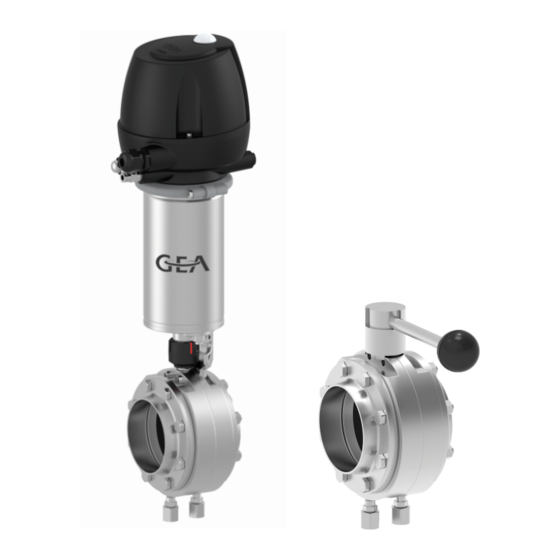
Description Pneumatic Butterfly Valve with Control Top Description Pneumatic Butterfly Valve with Control Top Fig.4 Designation Pneumatic Actuator T.VIS control top Mounting bracket Butterfly valve body Pneumatic Butterfly Valve without Control Top Fig.5 Designation Pneumatic Actuator Mounting bracket Butterfly valve body Electrical feedback - proximity switch Optional in the mounting bracket... -
Page 18: Butterfly Valve Body Without Actuator
Description Butterfly Valve Body without Actuator Butterfly Valve Body without Actuator Fig.6 Butterfly valve design for matrix-piped systems. Manual Actuator Type H Various manual actuator variants are available. Standard design of manual actuator Fig.7 Manual actuator variants Standard Optional – one electrical feedback signal Optional –... -
Page 19: Functional Description
Description Functional description Functional description 3.5.1 Pneumatic Actuator The compressed air which enters above the piston causes a downwards movement of the piston and the disk of the butterfly valve opens. When the air supply is shut off, the valve closes automatically as a result of the spring force. The stroke of the piston is converted into a rotary movement of the shaft. -
Page 20: Manual Actuator Type H
Description Functional description 3.5.4 Manual Actuator Type H Fig.10 To open or close the mixproof butterfly valve, unlock the hand lever (1) by gently pulling it out of the locking device and turn it through 90°. When the lever is released, it locks into place in the holes provided. - Page 21 Description The mixproof butterfly valve is used for separating media. The valve disk (1) as the shut-off element is supported between two flanges screwed together (2, 3) and plain bearings (5). The valve positions are OPEN / CLOSED. In the CLOSED position, two media can be reliably separated from one another. The leakage cavity is open towards the atmosphere in this case.
-
Page 22: Transport And Storage
Transport and storage Storage conditions Transport and storage Storage conditions Valves or spare parts should be stored in a dry place, free of vibrations and dust, and protected from light. To avoid damage, leave the components in their original packaging if possible. If, during transport or storage, the valve is going to be exposed to temperatures ≤... -
Page 23: Technical Data
Type plate The type plate clearly identifies the valve. Fig.12 The type plate provides the following key data: Key data of the leakage butterfly valve Type Hygienic leakage butterfly valve ECOspace Serial Serial number Material 1.4404/AISI 316L Control air pressure bar/psi min. - Page 24 Technical data Technical data Technical data: Ambient temperatures Designation Description - Control top type T.VIS M-15, A-15 -20 to +50 °C (-4 ... +122 °F) - Control top type T.VIS P-15 0 to +50 °C (-4 ... +122 °F) Product and operating temperature -40 to +135°C Technical data: Compressed air supply Designation...
-
Page 25: Resistance Of Sealing Materials
Technical data Resistance of Sealing Materials Equipment: Proximity switches – actuator without T.VIS Operating voltage [V] 10...65 DC 20...25 AC Switching distance [mm] Max. continuous current >3...<100 >3...<100 [mA] Ambient temperature [°C] -25...+80 -25...+80 Protection class IP 67 IP 67 Resistance of Sealing Materials The resistance of sealing materials depends on the type and temperature of the medium conveyed. -
Page 26: Pipe Ends - General Table Of Measurements
Technical data Pipe ends - General table of measurements Sealing resistance table Sealing material (general operation temperature) Medium at permissible EPDM HNBR operating -40...+135°C* -10...+200 °C* -25...+140 °C* -50...+200 °C* temperature (-40...275°F*) (+14...+392°F*) (-13...+284°F*) (-58...+392 °F*) Fuels/ – hydrocarbons Product with a fat content up to Product with a fat content of more... -
Page 27: Tools
Technical data Tools Dimensions for Pipes in Inch OD Outside Outside Wall Inside Inch OD diameter acc. diameter thickness diameter to BS 4825 0.5" 12.7 1.65 0.75" 19.05 1.65 15.75 1" 25.4 1.65 22.1 1.5" 38.1 1.65 34.8 2" 50.8 1.65 47.5 2.5"... -
Page 28: Lubricants
Technical data Lubricants Lubricants Lubricants Material no. Rivolta F.L.G. MD-2 413-071 PARALIQ GTE 703 413-064 Weights TYPE GS Mixproof butterfly valve with drive [kg] Size Pneumatic actuator Pneumatic actuator with Manual actuator without control top T.VIS control top DN 50, 2" 2 1/2"... -
Page 29: Assembly And Installation
Reliably secure sections of the plant which have already been connected against inadvertently being switched on. Notes on installation The mixproof butterfly valve ECOspace should be installed in horizontal pipes, with the actuator in vertically upright position; in special applications the actuator can also be installed at a 30° tilt. -
Page 30: Establishing Hose Connections
Assembly and installation Electrical connections Air requirement (dm stroke) dm at 1.01325 Actuator type Actuator Ø (mm) bar at 0°C in accordance with DIN 1343 DN 50, DN 65 88.9 0.325 2" OD, 2.5" OD DN 80, DN 100 114.3 0.530 3"... -
Page 31: Electrical Connection With T.vis Control Top
Assembly and installation Electrical connections 6.4.1 Electrical connection with T.VIS control top Danger Live parts Electrical shock can result in serious personal injury or death. ► Only allow properly qualified staff to carry out work on the electrical equipment. ► Prior to establishing electrical connections check the maximum permissible operating voltage. - Page 32 Assembly and installation Hold the proximity switch and turn the cap nuts until a switching gap of max. 4 mm to the associated contact element is achieved. Tighten the cap nuts. ® Done. 430BAL010337EN_7 29.07.2021...
-
Page 33: Start-Up
Start-up Safety instructions Start-up Safety instructions Initial commissioning For initial commissioning, the following principles apply: • Take protective measures against dangerous contact voltages in accordance with pertinent regulations. • The valve must be completely assembled and correctly adjusted. All screw connections must be securely tightened. -
Page 34: Operation And Control
Operation and control Safety instructions Operation and control Safety instructions Dangerous situations during operation can be avoided by safety-conscious and proactive behaviour of the personnel. For operation, the following principles apply: • Monitor the component during operation. • Safety devices must not be changed, removed or taken out of service. Check all safety devices at regular intervals. -
Page 35: Cleaning
Cleaning Cleaning Cleaning Cleaning All parts in contact with product must be cleaned at regular intervals. Always observe the safety data sheets issued by the cleaning agent manufacturers. Only use cleaning agents which do not cause damage to the seals and the inner parts of the valve. -
Page 36: Cleaning The Leakage Cavity
Cleaning Cleaning 9.1.3 Cleaning the Leakage Cavity On the mixproof butterfly valve, two connections for flushing are provided at the deepest point of the housing to enable cleaning of the leakage cavity. A special sealing mechanism allows the valve to be operated without any additional shut-off valves. -
Page 37: Passivation
Cleaning Passivation Depending on the cleaning method (medium concentration, temperature and contact times), the seals are affected to different degrees. This can impair the function and the service life. Passivation Before commissioning a plant, passivation is commonly carried out for long pipes and tanks. -
Page 38: Maintenance
Maintenance Safety notes Maintenance 10.1 Safety notes Maintenance and repair Before carrying out maintenance and repair work on the component's electrical equipment, perform the following steps in accordance with the "5 safety rules": • Isolate from the power supply • Take appropriate measures to prevent switch on •... -
Page 39: Inspections
Maintenance Inspections • Disconnect all power and utility lines. • Markings, e.g. on lines, must not be removed. • Do not climb on the component. Use suitable access aids and working platforms. • Mark the lines (if unmarked) prior to disassembly to ensure they are not confused when re-assembling. -
Page 40: Maintenance Intervals
Maintenance Maintenance intervals Check the signs on the valve. Replace damaged or missing stickers with new ones. ® Done 10.3 Maintenance intervals To ensure the highest operational reliability of the valves, all wearing parts should be replaced at longer intervals. The actual maintenance intervals can only be determined by the user since they depend on the operating conditions, for instance: •... -
Page 41: Removing The T.vis M-15 Control Top
Maintenance Disassembling the Valve 10.5.1 Removing the T.VIS M-15 Control Top Fig.13 Prerequisite: • The pneumatic and electrical connections on the plant side can remain on the control top. Notice The permanent magnet on the switch bar is fragile. Damage to the permanent magnet. ►... -
Page 42: Removing The T.vis A-15 Control Top
Maintenance Disassembling the Valve 10.5.2 Removing the T.VIS A-15 Control Top Fig.14 Prerequisite: • The pneumatic and electrical connections on the plant side can remain on the control top. Notice The permanent magnet on the switch bar is fragile. Damage to the permanent magnet. ►... -
Page 43: Removing The Valve
Maintenance Disassembling the Valve 10.5.3 Removing the Valve Fig.15 Carry out the following steps: Undo the screw connections (3). Remove the valve from the pipe. ® Done. 10.5.4 Disassembling the Pneumatic Actuator 10.5.4.1 Taking off the Actuator Fig.16 Carry out the following steps: Undo the screw connections (1). -
Page 44: 10.5.4.2 Dismantling The Actuator Parts
Maintenance Disassembling the Valve 10.5.4.2 Dismantling the Actuator Parts Fig.17 Carry out the following steps: Undo the screw connections (7). Take off the position indicator (2). Remove the mounting bracket (6). ® Done. 10.5.5 Disassembling the Manual Actuator Removing the proximity switch Fig.18 Carry out the following steps: Use an a/f 4 hex socket screwdriver to unscrew the locking screw (2) until it is... -
Page 45: Removing The Valve Disk Seal
Maintenance Disassembling the Valve Removing the Manual Actuator Fig.19 Carry out the following steps: Use an a/f 4 hex socket screwdriver to unscrew the locking screw (2) until it is flush with the bushing. Take off the hand lever (1). ®... -
Page 46: Maintenance
Maintenance Maintenance ® Done. Removing the Seal Carry out the following steps: Pull off the plain bearings (5). Turn the disk seal (6) until it is positioned at a 90° angle to the valve disk (4). Fig.21 Pull the disk seal over the free end (12) of the valve disk. Unclamp the valve disk. -
Page 47: Lubricating Seals And Threads
Maintenance Maintenance Notice Damage to the valve Damage to the valve can result in a malfunction. ► Observe the safety information sheets issued by the detergent manufacturers! ► Only use detergents which are non-abrasive and not aggressive towards stainless steel. ►... -
Page 48: Installation
PARALIQ GTE 703 can be ordered from GEA Tuchenhagen under material no. 413-064, and Rivolta F.L.G. MD-2 can be ordered under material no. -
Page 49: Torques For The Clamps And Bolts
Maintenance • When the actuator is mounted, the valve disk must be in the correct position: for resting position closed: valve disk closed for resting position open: valve disk at 90° position. • Installation outer flange type VV: Arrange additional holes so that bracket can be dismantled in assembled condition. -
Page 50: Alarms
Alarms Malfunctions and remedies Alarms 11.1 Malfunctions and remedies In the event of malfunctions immediately deactivate the mixproof butterfly valve and secure it against inadvertent reactivation. Malfunctions may only be remedied by qualified staff, who must observe the safety instructions. Malfunction Cause Remedy... -
Page 51: Decommissioning
► Never open the actuator. ► GEA Tuchenhagen accepts unopened actuators and arranges for proper disposal free of charge. Carry out the following steps: Remove the actuator. Pack the actuator safely and send it to GEA Tuchenhagen GmbH. ® Done. 430BAL010337EN_7 29.07.2021... -
Page 52: Parts List - Hygienic Leakage Butterfly Valve Ecospace
Parts list - Hygienic leakage butterfly valve ECOspace Parts list - Hygienic leakage butterfly valve ECOspace Fig.25: Items marked with an * are wearing parts. 430BAL010337EN_7 29.07.2021... - Page 53 Parts list - Hygienic leakage butterfly valve ECOspace Item Designation Material DN 50 DN 65 DN 80 DN 100 Sealing set cpl. EPDM 224-000696 224-000697 224-000698 224-000699 Flap BFV-L 1.4404 224-000583 224-000585 224-000540 224-000568 Seal BFV-L EPDM 224-000570 224-000571 224-000535...
-
Page 54: Spare Parts List - Pneumatic Actuator Hygienic Leakage Butterfly Valve
Spare parts list - Pneumatic actuator hygienic leakage butterfly valve Spare parts list - Pneumatic actuator hygienic leakage butterfly valve Fig.26 430BAL010337EN_7 29.07.2021... - Page 55 Spare parts list - Pneumatic actuator hygienic leakage butterfly valve Fig.27 430BAL010337EN_7 29.07.2021...
- Page 56 Spare parts list - Pneumatic actuator hygienic leakage butterfly valve Item Designation Material DN 50 DN 65 DN 80 DN 100 2" OD 2.5" OD 3" OD 4" OD Actuator BFV-7 / NC/NO/ cpl. 224-001822 224-001822 224-001821 224-001821 A (opt.) Actuator BFV-7/NC/NO/cpl./EX 224-001831 224-001831...
-
Page 57: Dimension Sheet - Manual Operation Hygienic Leakage Butterfly Valve
Dimension sheet - Manual operation hygienic leakage butterfly valve Dimension sheet - Manual operation hygienic leakage butterfly valve Fig.28: Manual actuator for BFV-L Fig.29: Installation variants for proximity switches 430BAL010337EN_7 29.07.2021... - Page 58 Dimension sheet - Manual operation hygienic leakage butterfly valve Item Designation Nominal width Nominal width DN 25 - DN 65 DN 100 / DN 80 2" OD - 2.5" OD 3” OD / 4” OD Square 12 mm 14 mm Manual actuator 224-001055 224-001056...
-
Page 59: Dimension Sheet - Hygienic Leakage Butterfly Valve Ecospace
Dimension sheet - Hygienic leakage butterfly valve ECOspace Dimension sheet - Hygienic leakage butterfly valve ECOspace Fig.30: Installation of proximity switches optional / observe removal reserve 430BAL010337EN_7 29.07.2021... - Page 60 Dimension sheet - Hygienic leakage butterfly valve ECOspace Item Designation Dimension DN 50 DN 65 DN 80 DN 100 2" OD 2.5" OD 3" OD 4" OD Pneumatic actuator with T.VIS control top, installation dimension X 47.5 47.5 47.5 47.5 D / actuator Ø...
-
Page 61: Dimension Sheet - Hygienic Butterfly Valve - Seals
Dimension sheet - Hygienic butterfly valve - seals Dimension sheet - Hygienic butterfly valve - seals Fig.31 430BAL010337EN_7 29.07.2021... - Page 62 Dimension sheet - Hygienic butterfly valve - seals Nominal width Material Material DN 50 EPDM 224-000570 56.3 63.2 28.0 DN 65 EPDM 224-000571 74.1 82.7 28.0 DN 80 EPDM 224-000535 88.9 97.5 31.0 DN 100 EPDM 224-000573 109.1 118.7 32.0 2"...
-
Page 63: Appendix
Appendix Lists Appendix 18.1 Lists 18.1.1 Abbreviations and terms Abbreviation Explanation British Standard Unit of measurement of pressure [bar] All pressure data expressed in [bar/psi] is assumed to be gauge pressure [barg/psig] unless explicitly specified otherwise. approx. approximately °C Unit of measurement of temperature [degree Celsius] Unit of measurement of volume [cubic decimetre] Standard volume (standard litres) DIN nominal width... - Page 64 Appendix Abbreviation Explanation Metric Unit of measurement of work [newton metre] SPECIFIED TORQUE: 1 Nm = 0.737 lbft Pound-Force (lb) + Feet (ft) Polyamide PE-LD Low-density polyethylene Polytetrafluoroethylene Anglo-American measurement of pressure [pound-force per square inch] All pressure data expressed in [bar/psi] is assumed to be gauge pressure [barg/psig] unless explicitly specified otherwise.
- Page 65 Appendix 430BAL010337EN_7 29.07.2021...
Need help?
Do you have a question about the ECOspace and is the answer not in the manual?
Questions and answers