Sign In
Upload
Manuals
Brands
GEA Manuals
Control Unit
VARIVENT 24/7 PMO
GEA VARIVENT 24/7 PMO Manuals
Manuals and User Guides for GEA VARIVENT 24/7 PMO. We have
2
GEA VARIVENT 24/7 PMO manuals available for free PDF download: Operating Instructions Manual, Original Operating Instructions
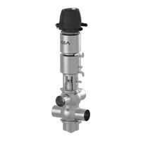
GEA VARIVENT 24/7 PMO Operating Instructions Manual (108 pages)
Hygienic valves
Brand:
GEA
| Category:
Control Unit
| Size: 7.79 MB
Table of Contents
Table of Contents
3
General Information
7
Information on the Document
7
Binding Character of These Operating Instructions
7
Notes on the Illustrations
7
Symbols and Highlighting
7
Manufacturer Address
8
Contact
8
EU Declaration of Conformity in Accordance with the EC Machinery Directive 2006/42/EC
9
Translated Copy of the EU - Declaration of Conformity in Accordance with the Pressure Equipment Directive 2006/42/EU
10
UK Declaration of Conformity for the Delivery of Machines (Safety) Dated 2008
11
Safety
12
Intended Use
12
Requirements for Operation
12
Pressure Equipment Directive
12
ATEX Directive
12
Improper Operating Conditions
13
Operator's Duty of Care
13
Subsequent Changes
14
General Safety Instructions and Dangers
14
Principles for Safe Operation
14
Environmental Protection
15
Electrical Equipment
15
Supplementary Regulations
15
Qualification of Personnel
15
Safety Equipment
17
Signage
17
Residual Dangers
18
Danger Zones
19
Description
22
Design
22
Functional Description
24
Leakage-Proof Shut-Off
24
Cleaning by Lifting
24
Actuator Function
24
Transport and Storage
25
Storage Conditions
25
Transport
25
Scope of Supply
26
Technical Data
27
Type Plate
27
Resistance and Permitted Operating Temperature of the Sealing Materials
28
Pipe Ends - General Table of Measurements
29
Tool
30
Lubricants
31
Weights
31
Assembly and Installation
32
Safety Instructions
32
Notes on Installation
32
Control Head
32
Valve with Detachable Pipe Connection Elements
32
Valve with Welded Ends
33
Pneumatic Connections
34
Air Requirement
34
Establishing Hose Connections
34
6.6.2.1 Hose Connection Plan - Mixproof Valves M/2.0 with Control Top T.VIS
35
Electrical Connection with T.VIS Control Top
36
Adjustment of the Control Top
36
6.7.1.1 Control Top T.VIS A-15 Adjustment
36
6.7.1.2 Control Top T.VIS M-15 Adjustment
38
Adjustment of the Initiators in the Lantern
41
6.7.2.1 Fitting the Sliding Piece
41
6.7.2.2 Set the Slider
42
6.7.2.3 Fitting the Proximity Switch
43
6.7.2.4 Set the Proximity Switch
43
Test Procedure According to PMO for Valve Type M
45
Test Procedure 1
45
Hardware Description
46
Start-Up
48
Safety Instructions
48
Notes on Commissioning
48
Operation and Control
49
Safety Instructions
49
Feedback System / Signal Analysis
49
Cleaning
50
Cleaning Process Examples
50
Cleaning Effect
50
Cleaning the Leakage Outlet of the Mixproof Valve Type M/ 2.0
51
Cleaning of the Lower Balancer
51
Examples for Cleaning by Lifting
51
Passivation
51
Maintenance
53
Safety Instructions
53
Inspections
54
Product Contact Seals
54
Pneumatic Connections
54
Electrical Connections
55
Maintenance Intervals
55
Prior to Removal
56
Disassembly
56
Start Disassembly
56
Removing the Control Top
60
Disconnecting the Valve from the Housing
61
Removing the Valve Disk
63
Dismantle Double-Disk
64
Dismantle Lifting Actuator
65
Disassembly Sterile Lock
67
Disassembly Balancer Plug
67
Installation
68
Tightening Torques
69
Fitting the Lifting Actuator
69
Installing the Valve
72
Mount the Switch Bar and Control Top
77
Assembly Balancer Plug
78
Fit the Sterile Lock
78
Installing the Valve in the Housing
79
Checking the Function
82
10.6.8.1 Checking the Valve Stroke
82
10.6.8.2 Check the Lift Stroke
82
Maintenance
82
Cleaning the Valve
82
Replacing Seals
83
10.7.2.1 Replacing V-Ring RA on the Double-Disk and Valve Disk
83
10.7.2.2 Replace more Seals
85
10.7.2.3 Lubricating Seals and Threads
85
Alarms
88
Malfunctions and Remedies
88
Decommissioning
89
Safety Instructions
89
Disposal
89
General Notes
89
Valve Actuator Disposal
89
Spare Parts List - Mixproof Valve M/2.0 with Cleaning of Lower Balancer
90
Spare Parts List - Mixproof Valve M/2.0 Without Cleaning of Lower Balancer
95
Spare Parts List - Lifting Actuator
100
Dimension Sheet - Mixproof Valve Type M
103
Appendix Lists
105
Abbreviations and Terms
105
Advertisement
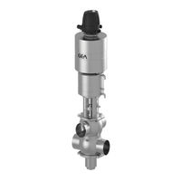
GEA VARIVENT 24/7 PMO Original Operating Instructions (93 pages)
Cheese Curd Valve
Brand:
GEA
| Category:
Control Unit
| Size: 4.91 MB
Table of Contents
Table of Contents
3
Notes for the Reader
6
Binding Character of These Operating Instructions
6
Notes on the Illustrations
6
Symbols and Highlighting
7
Abbreviations and Terms
8
Safety
10
Safety Note
10
Operator's Duties
10
Qualification of Staff
11
Supplementary Regulations
12
Instructions for the Safe Operation
13
General Principles
13
Installation
14
Commissioning/Setup Mode
14
Setting into Operation
15
Operation
15
Shutting down
15
Maintenance and Repair
16
Disassembly
17
Environmental Protection
17
Electrical Equipment
17
Signage
18
Residual Risk
19
Hazard Areas
19
Residual Dangers
21
Declaration of Conformity
22
Transport and Storage
23
Scope of Supply
23
Transport
23
Storage
24
Intended Purpose
25
Designated Use
25
Requirements for the Operation
25
Pressure Equipment Directive
25
Improper Operating Conditions
25
Conversion Work
26
Design and Function
27
Design
27
Leakageproof Shut-Off
28
Actuator Function
28
Installation
29
Notes on Installation
29
Valve with Detachable Pipe Connection Elements
29
Valve with Welding Ends
30
Pneumatic Connections
31
Air Requirement
31
Establishing the Hose Connection
31
Hosing Diagram
32
Electrical Connections and Commissioning
33
Connecting the Valve
33
Adjusting the Position Detecting Devices
34
Adjusting Control Top T.VIS A-15
34
Adjusting Control Top T.VIS M-15
36
Adjusting the Proximity Switch in the Lantern on Double-Disks Without Balancer
39
Adjusting of the External Sensor in the Lantern
41
Test Procedures for Tuchenhagen PMO Valve Type M-C/2.0
47
Purpose
47
Test Procedure Overview
47
Hardware Description
47
Test Procedure 1
48
Test Procedure 2
49
Commissioning
49
Cleaning and Passivation
50
Cleaning
50
Typical Cleaning Parameters in Dairy Operations
50
Cleaning of the Leakage Outletsystem
50
Examples of Cleaning by Lifting
51
Passivation
51
Malfunctions
52
Maintenance
53
Inspections
53
Product Contact Seals
53
Pneumatic Connections
53
Electrical Connections
53
Maintenance Intervals
54
Prior to Dismantling the Valve
54
Disassembling
55
Depressurizing the Actuator
55
Removing the Control Top and the Switch Bar
56
Separating the Valve from the Housing
57
Dismantling the Valve Disk
58
Dismantling the Double Valve Disk
59
Dismantling the Lifting Actuator
60
Maintenance
61
Cleaning the Valve
61
Removing V-Ring RA
62
Inserting V-Ring RA
63
Lubricating Seals and Threads
64
Assembling
66
Assembling the Lifting Actuator
66
Assembling the Valve
68
Mounting the Switching Rod and the Control Top
72
Insert the Valve into the Housing
73
Torques of the Semi-Annular Clamps and Clamp Joints
73
Checking the Function
74
Disposal
74
General Notes
74
Valve Actuator Disposal
75
Technical Data
76
Type Plate
76
Resistance of Sealing Materials
78
Pipe Ends
79
Weights
79
Tools
80
Lubricants
80
Spare Parts Lists
81
Advertisement
Related Products
GEA VARIVENT N V
GEA VARIVENT W V
GEA VARIVENT T R
GEA VARIVENT T L
GEA VARIVENT T RC
GEA VARIVENT MT/T R 08
GEA VARIVENT K
GEA VARIVENT T R Series
GEA VARIVENT T RL Series
GEA VARIVENT T RC Series
GEA Categories
Control Unit
Air Compressor
Water Pump
Compressor
Control Systems
More GEA Manuals
Login
Sign In
OR
Sign in with Facebook
Sign in with Google
Upload manual
Upload from disk
Upload from URL