
Related Manuals for Stryker Power-PRO XT


Summary of Contents for Stryker Power-PRO XT
- Page 1 Power-PRO™ XT 6506 Operations Manual 2017/09 F.2 6506-209-001 REV F www.stryker.com...
- Page 2 sample text...
- Page 3 Warning; non-ionizing radiation No pushing Do not lubricate Catalogue number Lot (batch) code Serial number For US Patents see www.stryker.com/patents Manufacturer Date of manufacture Mass of equipment with safe working load Safe working load Type B applied part Type BF applied part www.stryker.com...
- Page 4 Contains nickel cadmium cells and should be recycled accordingly Battery terminal identification (data line, negative, and positive) DATA Ni-Cd cell identification per IEC 61951-1:20 03 23/44 2300 mAh Battery capacity, typical charge, and duration (1.2A/2h) 6506-209-001 REV F www.stryker.com...
- Page 5 Dealer No: DA35173/14 Product complies with applicable EMC standards in Australia/New Zealand Approved by independent communications authority of South Africa Box manufacturer’s certificate - this packaging box has a minimum test value of 500 lb per sq. www.stryker.com 6506-209-001 REV F...
- Page 6 sample text...
-
Page 7: Table Of Contents
Loading or unloading a cot with the Power-LOAD option................32 Loading a cot into a vehicle with an antler style cot fastener ............... 33 Unloading a cot from a vehicle with an antler style cot fastener ..............34 Positioning operators and helpers ......................36 www.stryker.com 6506-209-001 REV F... - Page 8 Installing the optional mounting bracket ....................63 Installing the charger onto the optional mounting bracket ................64 Powering the charger ......................... 65 Disconnecting the charger........................66 Accessories ............................67 Cleaning..............................68 Suggested cleaners ........................... 68 Cleaning the charger.......................... 69 6506-209-001 REV F www.stryker.com...
- Page 9 Foot end fastener part replacement schedule..................74 EMC information ............................. 75 Warranty ............................... 79 Warranty exclusion and damage limitations..................... 79 To obtain parts and service........................80 Return authorization........................... 80 Damaged product ..........................80 International warranty clause ....................... 80 www.stryker.com 6506-209-001 REV F...
-
Page 10: Warning/Caution/Note Definition
Note: Provides special information to make maintenance easier or important instructions clearer. 6506-209-001 REV F www.stryker.com... -
Page 11: Summary Of Safety Precautions
X-frame cots, but a rail clamp assembly is required for all cots without the Power-LOAD option. • Always make sure that you use a Power-LOAD date of manufacture cot with the Stryker Model 6390 Power-LOAD system to avoid the risk of injury. - Page 12 Always use only non-conductive materials to wipe the SMRT Pak. • Always refer to the disinfectant’s Material Safety Data Sheet (MSDS) to verify the pH range. Disinfectants with pH levels higher than 10.5 may cause the SMRT Pak housing material to crack. 6506-209-001 REV F www.stryker.com...
- Page 13 Always place the electrical SMRT charger power cord where it will not be stepped on, tripped over, or otherwise subjected to damage or stress. • Do not touch the SMRT Pak receptacle terminals with metal objects. www.stryker.com 6506-209-001 REV F...
-
Page 14: Pinch Points
If such use is necessary, carefully observe Power-PRO and SMRT charger and the other equipment to make sure that they are operating properly. Pinch points WARNING Always keep your hands clear of the red safety bar pivots when you load, unload, or change the height position of the cot. 6506-209-001 REV F www.stryker.com... -
Page 15: Mechanical Stability
Summary of safety precautions Pinch points (Continued) Figure 1: Pinch points Mechanical stability WARNING Always use both hands when you transport the cot. www.stryker.com 6506-209-001 REV F... - Page 16 If the cot is on a plane steeper than five degrees, place the cot in the lowest position. • Do not use the defibrillator option and the foot end oxygen bottle holder option at the same time. 6506-209-001 REV F www.stryker.com...
-
Page 17: Introduction
Power-PRO XT is not intended for extended stay or use as a hospital bed or in devices that modify air pressure, such as hyperbaric chambers. -
Page 18: Expected Service Life
Recommended loading height Up to 36 in. Up to 91 cm Recommended working height (excluding mattress) 15.75 in. 40 cm Hydraulic oil Stryker part number 6500-001-293 Power system Battery 24 VDC NiCd - SMRT power system 6506-209-001 REV F www.stryker.com... - Page 19 Set the cot height to any ambulance deck height that ranges from 26 in. to 36 in. (66 cm to 91 cm). Stryker reserves the right to change specifications without notice. Power-PRO XT is designed to conform to the Federal Specification for the Star-of-Life Ambulance (KKK-A-1822 ). Power-PRO XT is designed to be compatible with some competitive cot fastener systems.
-
Page 20: Standards With Required Options
The Britax Meridian SICT Series No. 7200/A/2010 Convertible Child Restraint with the X-restraint package (6500-001- 430) has been dynamically crash tested with a 10 kg crash dummy to 18.2 G forward and 10 G sideward per AS/NZS- 4535: 1999 crash-test standards. 6506-209-001 REV F www.stryker.com... -
Page 21: Specifications - Smrt
Relative Atmospheric pressure 1060 hPa 1060 hPa 1060 hPa Specifications are approximate and may vary from unit to unit or as a result of power supply fluctuations. Stryker reserves the right to change specifications without notice. www.stryker.com 6506-209-001 REV F... -
Page 22: Product Illustration - Power-Pro
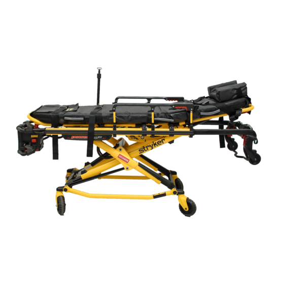
Introduction Product illustration - Power-PRO Figure 3: Power-PRO XT Footrest release handle Siderail release handle Height adjustment switches Transport wheels Manual back-up release handle Backrest Backrest adjustment handle Footrest Height sensor housing (on other side) Retractable head section Wheel lock... -
Page 23: Product Illustration - Smrt
Portage, MI 49002 To view your operations or maintenance manual online, see https://techweb.stryker.com/. Have the serial number (A) of your Stryker product available when calling Stryker Customer Service or Technical Support. Include the serial number in all written communication. www.stryker.com... -
Page 24: Serial Number Location - Power-Pro
The serial number for the SMRT charger is located on the bottom of the unit. The lot number for the SMRT Pak is located on the top of the SMRT Pak above the red release button. Date of manufacture The year of manufacture is the first 2 digits of the serial number for Power-PRO. 6506-209-001 REV F www.stryker.com... -
Page 25: Setup
Smooth rear edge for product loading • Level floor large enough for the folded product • Stryker cot fastener system • Space to install the vehicle safety hook • In fastener shut-off module installed, if using an antler style cot fastener Note: Loose items or debris on the vehicle patient compartment floor can interfere with the operation of the vehicle safety hook and product fastener. -
Page 26: Installation
Installation Installing the cot fastener The Stryker cot fastener systems are compatible only with cots that conform to the installation specifications. WARNING • Install the cot fastener by qualified personnel only. Improper installation could result in injury to the patient or operator. -
Page 27: Selecting The Vehicle Safety Hook
The vehicle safety hook was designed for compatibility and proper operation when loading and unloading the cot from a vehicle that is compliant with Federal Regulation KKK-A-1822. Stryker offers three different types of vehicle safety hooks that are ordered and shipped with your cot. These vehicle safety hook types meet the needs of various emergency vehicle configurations, specifically the length and location of the floor structure support that is located in the rear of the vehicle. -
Page 28: Vehicle Configuration
2 in. (± 5 cm) from the vehicle floor to the ground level, which is defined as the vehicle deck height. Installation of the vehicle safety hook into any vehicle compliant with this federal specification provides adequate clearance for the cot base to lower to its fully extended position. 6506-209-001 REV F www.stryker.com... -
Page 29: Positioning Of The Vehicle Safety Hook, Front To Back
Make sure that you have adequate bumper clearance to allow the cot to be loaded and unloaded from the vehicle. Confirm the side to side placement of the vehicle safety hook (Positioning of the vehicle safety hook, side to side on page 24). www.stryker.com 6506-209-001 REV F... -
Page 30: Positioning Of The Vehicle Safety Hook, Side To Side
Make sure that the position marked in step 3 is where the cot safety bar connects with the vehicle safety hook every time when you unload the cot in a variety of positions (such as all the way to the left and all the way to the right). 6506-209-001 REV F www.stryker.com... -
Page 31: Installing The Vehicle Safety Hook
Drill the holes for the screws. Fasten the vehicle safety hook to the vehicle patient compartment floor. Make sure that the cot safety bar connects with the vehicle safety hook before you remove the cot from the vehicle patient compartment. www.stryker.com 6506-209-001 REV F... - Page 32 Figure 11: Vehicle safety hook placement Top view of vehicle Vehicle safety hook Squad bench Bumper Door frame After installation, make sure that the cot legs lock into the load position without contacting the vehicle bumper. 6506-209-001 REV F www.stryker.com...
-
Page 33: Operation
SMRT Pak is rated for 2.4 amp-hours of electric energy. WARNING Do not remove the battery when the cot is active. CAUTION Always charge the battery before you place the product into service. An uncharged or depleted battery may cause poor product performance. www.stryker.com 6506-209-001 REV F... -
Page 34: Checking The Hour Meter And Error Display
The LED is a solid amber to indicate a battery error. Notes • Only use Stryker approved batteries. • If equipped, the powered cot fastener automatically charges the SMRT Pak battery. Automatic charging occurs when you lock the cot into the powered cot fastener (no cable or connectors required). The cot battery LED indicator flashes green for a moment to signify that it is charging. -
Page 35: Operating Guidelines
Always load or unload an occupied cot with a minimum of two trained operators. Two operators must be present when a cot is occupied. Stryker recommends that both operators are at the foot end to reduce the load on each operator. -
Page 36: Transferring The Patient To The Cot
Always follow proper hand placement on hand grips. Keep all hands clear of the red safety bar pivots when you load or unload the cot or change cot height position. CAUTION Do not use the jog function to jog past the set cot load height after the cot safety bar connects with the vehicle safety hook. 6506-209-001 REV F www.stryker.com... -
Page 37: Raising, Lowering, Or Releasing The Cot With Power
Press to unlock the cot (for use with Power-LOAD only) Retract (-) Press and hold to lower the litter or retract the cot undercarriage Extend (+) Press and hold to raise the litter or extend the cot undercarriage www.stryker.com 6506-209-001 REV F... -
Page 38: Raising Or Lowering The Cot Manually With The Manual Override
X-frame cots, but a rail clamp assembly is required for all cots without the Power-LOAD option. • Always make sure that you use a Power-LOAD date of manufacture cot with the Stryker Model 6390 Power-LOAD system to avoid the risk of injury. -
Page 39: Loading A Cot Into A Vehicle With An Antler Style Cot Fastener
Stryker recommends that both operators are at the foot end to reduce the load on each operator. One or two operators can lift from the foot end of the cot. The higher an operator must lift the cot, the more difficult it may be to hold the weight. -
Page 40: Unloading A Cot From A Vehicle With An Antler Style Cot Fastener
Always make sure that the safety bar connects with the vehicle safety hook before you remove the cot from the vehicle patient compartment to avoid the risk of injury. • Do not pull or lift on the cot safety bar when you unload the cot. 6506-209-001 REV F www.stryker.com... - Page 41 Stryker recommends that both operators are at the foot end to reduce the load on each operator. One or two operators can lift from the foot end of the cot. The higher an operator must lift the cot, the more difficult it may be to hold the weight.
-
Page 42: Positioning Operators And Helpers
Remove the load wheels from the vehicle patient compartment floor. Positioning operators and helpers WARNING Always keep your hands clear of the red safety bar pivots when you load, unload, or change the height position of the cot. 6506-209-001 REV F www.stryker.com... -
Page 43: Raising Or Lowering The Backrest
Raising or lowering the siderails (XPS option) You can order your cot with the expandable patient surface (XPS) option or upgrade your cot to add the XPS option. WARNING Do not use siderails as a patient restraint device. www.stryker.com 6506-209-001 REV F... -
Page 44: Extending The Retractable Head Section
Always lock the head section into place before you operate the cot. • Do not load the cot into a vehicle with the head section retracted when using a cot fastener. The cot may tip or not connect with the cot fastener. 6506-209-001 REV F www.stryker.com... -
Page 45: Raising Or Lowering The Footrest
To lower the knee gatch in trend, lift the footrest frame (C), and while holding the frame, lift up on the red footrest release handle (B) until the frame releases the support bracket. Lower the footrest until it lays flat. Figure 15: Gatch www.stryker.com 6506-209-001 REV F... -
Page 46: Applying Or Releasing A Wheel Lock
To apply the kickstand: Operator 1: Apply the kickstand with your foot. Operator 2: Lift the foot end of the cot to actuate the kickstand. Both operators: Make sure that the kickstand is in the forward locked position. 6506-209-001 REV F www.stryker.com... -
Page 47: Securing The Patient With The G-Rated Restraint Straps
Secure restraint straps to the cot in the required attachment locations (Figure 16 on page 42). Restraint strap attachment locations should provide strong anchorage and proper restraint position. Do not allow restraint straps to interfere with www.stryker.com 6506-209-001 REV F... - Page 48 Securing the patient with the G-rated restraint straps (Continued) equipment or accessories. Buckle the restraint straps across the patient’s shoulders, waist, and legs. Buckle restraint straps when the cot is not in use. Figure 16: Restraint strap attachment points 6506-209-001 REV F www.stryker.com...
-
Page 49: Adjusting Restraint Straps
When you buckle a restraint strap around a patient, secure the latch plate and remove any loose webbing from the cot. Inspect the restraint straps at least once a month (more if used often). Check for a bent or broken receiver or latch plate, or torn or frayed webbing. Replace any worn or inoperable restraint strap. www.stryker.com 6506-209-001 REV F... -
Page 50: Securing A Patient With The X-Restraint/Rugged™-X (6500-001-430/6506-001-430) Restraint Straps
Installing the X-restraint/RUGGED-X shoulder restraints on page 45 Installing the X-restraint/RUGGED-X waist restraints on page 46 Installing the X-restraint/RUGGED-X thigh restraints on page 46 Installing the X-restraint/RUGGED-X ankle restraints on page 47 Installing the X-restraint/RUGGED-X ankle restraints on page 47 6506-209-001 REV F www.stryker.com... - Page 51 Pull the restraint buckle through the loop, toward the head end of the cot. Feed the buckle under the XPS System. For the Model 6506 Power-PRO XT cot and Model 6086 Performance-PRO XT cot, pull the restraint tight and toward the back of the backrest.
- Page 52 Wrap the restraint around the cot litter. Pull the restraint buckle through the loop, toward the head end of the cot. Pull the restraint tight. Connect the patient right buckle to the patient left buckle. Figure 26: Thigh restraints 6506-209-001 REV F www.stryker.com...
-
Page 53: Adding A Restraint Strap Extension
Securing a patient with the X-restraint/RUGGED™-X (6500-001-430/6506-001-430) restraint straps (Continued) Installing the X-restraint/RUGGED-X ankle restraints For Model 6506 Power-PRO XT cots and Model 6086 Performance-PRO XT cots built before July 3, 2015 with the gatch option only. To install the X-restraint/RUGGED-X ankle restraints: Wrap the restraint around the cot frame. -
Page 54: Securing The Patient With The Pedi-Mate® Infant Restraint System
Raise the cot fowler up to align with the back of the child restraint. Loop the upper anchorage strap with the anchor fitting and attachment clip from the child restraint around the cot fowler (Figure 30 on page 49). Pull the adjustment strap to tighten and remove slack. 6506-209-001 REV F www.stryker.com... - Page 55 10. Pull the restraint strap (6500-001-404) through the foot end of the child restraint (Figure 34 on page 50). 11. Firmly push down on the seat with your hand while pulling the restraint with the other hand to tighten the restraint. www.stryker.com 6506-209-001 REV F...
-
Page 56: Installing The Defibrillator Platform
Always change the installation location or adjust the straps for your specific defibrillator size or shape. • Do not load the defibrillator platform above the safe working load of 30 lb (13.6 kg). To install the defibrillator platform: Place the defibrillator platform in the stored position (Figure 36 on page 51). 6506-209-001 REV F www.stryker.com... - Page 57 Repeat on the other side. For Power-LOAD compatible cots, if equipped, you must lengthen and attach the straps to the foot end fastener (Figure 40 on page 52). Figure 38: Raise IV pole and position defibrillator tray Figure 39: Latch hook placement www.stryker.com 6506-209-001 REV F...
-
Page 58: Hanging Equipment From The Equipment Hook
Use the equipment hook to hang additional accessories or equipment, such as defibrillators and monitors. CAUTION • Do not load the equipment hook above the safe working load of 35 lb (15.8 kg). • Always remove all accessories or equipment from the equipment hook when in the vehicle. 6506-209-001 REV F www.stryker.com... -
Page 59: Installing The Head Extension With Pillow
Lift and pivot the IV pole from the storage position and push down until the IV pole locks into the receptacle (A). To raise the height of the pole, turn the lock actuator (B) counterclockwise and pull up on the telescoping portion (C) of the pole to raise it to the desired height. www.stryker.com 6506-209-001 REV F... -
Page 60: Positioning The Optional Three-Stage Iv Pole
Hang the IV bags on the IV hook (F). To lower the IV pole, push in on the spring clip (E) and slide section (D) down into section (C). Turn the lock actuator (B) counterclockwise and slide section (C) into the bottom tube. 6506-209-001 REV F www.stryker.com... -
Page 61: Attaching An Oxygen Bottle To The Oxygen Bottle Holder
To attach an oxygen bottle to the oxygen bottle holder: Place an oxygen bottle in the holder. Insert the lower strap through the buckle and affix the strap onto itself to secure the oxygen bottle to the holder. www.stryker.com 6506-209-001 REV F... -
Page 62: Attaching An Oxygen Bottle To The Retractable Head Section Oxygen Bottle Holder
Do not use the oxygen bottle holder to hold an oxygen bottle holder when the transport vehicle is in motion. Always place the oxygen bottle holder in an appropriate storage location when the transport vehicle is in motion. 6506-209-001 REV F www.stryker.com... -
Page 63: Installing The Optional Base Storage Net
To install the backrest storage pouch (Figure 47 on page 58): Insert each strap through a hole in the backrest skin. Mount the pouch flat against the backrest. Secure the backrest storage pouch to the cot with the Velcro straps. www.stryker.com 6506-209-001 REV F... -
Page 64: Installing The Optional Head End Storage Flat
(Figure 48 on page 59): Install the Velcro® straps (A) near the pneumatic cylinder and around the cross tube (C) of the retractable head section. Buckle the restraint straps (B) around the outer rails of the retractable head section. 6506-209-001 REV F www.stryker.com... -
Page 65: Transferring Larger Patients
Attach the strap at the foot end of the mattress through the two holes in the foot end skin on the cot litter. Pull the strap through the buckle and attach the Velcro to secure the strap. www.stryker.com 6506-209-001 REV F... -
Page 66: Installing A Smrt Pak
Installing a SMRT Pak The SMRT Pak is designed to be compatible with the Power-PRO XT, Power-PRO IT, and Power-PRO TL cots. To maximize available battery power, only use SMRT Paks that have been charged within the last 48 hours. -
Page 67: Storing The Battery
31 °C). Charging the SMRT Pak outside of this recommended temperature range reduces SMRT Pak life and extends charge time. To charge the SMRT Pak (Figure 50 on page 62): Insert a clean, dry SMRT Pak into the SMRT charger. Make sure that the SMRT Pak is locked into the SMRT charger. www.stryker.com 6506-209-001 REV F... -
Page 68: Checking The Smrt Pak Power Level With The Smrt Charger
Power connection: Connect or disconnect the SMRT charger from the appropriate power source (Powering the charger on page 65). • SMRT charger power LED (A): If the green LED is illuminated, then the SMRT charger has power. 6506-209-001 REV F www.stryker.com... -
Page 69: Electrical Power Installation Requirements
Always mount the SMRT charger to the optional mounting bracket in an enclosed cabinet and out of patient reach during transport to comply with established crash test standards. • Always make sure that the optional mounting bracket is securely attached to the surface. www.stryker.com 6506-209-001 REV F... -
Page 70: Installing The Charger Onto The Optional Mounting Bracket
(Figure 53 on page 65): Align the rear keyway slots (A) onto the bracket fasteners (B). Slide the SMRT charger (C) in until it locks into the mounting bracket (D) to secure the charger to the bracket. 6506-209-001 REV F www.stryker.com... -
Page 71: Powering The Charger
Locate the power connection (A) on the back of the SMRT charger. Push the power cord retention tab (B) in to insert the power cord outlet connector into the SMRT charger power connection. Plug the power adaptor end of the power cord into the power source. www.stryker.com 6506-209-001 REV F... -
Page 72: Disconnecting The Charger
It is a best practice to use a clean, uninterruptible power source. The SMRT charger continuously illuminates a solid green power LED when it is connected to a power supply. Use only Stryker-approved parts to power the SMRT charger. Figure 54: Powering the charger... -
Page 73: Accessories
Accessories These accessories may be available for use with your product. Confirm availability for your configuration or region. Call Stryker Customer Service: 1-800-327-0770. Name Number Defibrillator platform 6506-170-000 Equipment hook 6500-147-000 Head extension with pillow 6100-044-000 IV pole, two-stage, right... -
Page 74: Cleaning
• Follow the cleaning solution manufacturer’s dilution recommendations exactly. • The preferred method Stryker Medical recommends for power washing the product is with the standard hospital surgical cart washer or hand held wand unit. • Clean the cot once a month. -
Page 75: Cleaning The Charger
Do not exceed 1500 psi (130.5 bar) as the maximum water pressure. If you use a hand held wand to wash the product, keep the pressure nozzle at a minimum of 24 in. (61 cm) from the product. www.stryker.com 6506-209-001 REV F... - Page 76 Rinse the SMRT Pak thoroughly with clean water to remove any cleaning chemical or residue. Position the SMRT Pak to avoid water from pooling near the terminals. Dry the SMRT Pak thoroughly before insert the SMRT Pak into a Power-PRO cot or SMRT charger. 6506-209-001 REV F www.stryker.com...
-
Page 77: Preventive Maintenance
If you are unsure how to perform these checks, contact your Stryker service technician. If you are in doubt as to what intervals to follow to maintain your product, consult your Stryker service technician. Check each routine and replace worn parts if necessary. - Page 78 All fasteners are secure Backrest cylinder operates Adjust pneumatic cylinder for full range of motion, if required Base All fasteners are secure X-frame X-frame expands and retracts Kickstand (optional) Retracts fully to the transport position Bolts are tightened 6506-209-001 REV F www.stryker.com...
- Page 79 Head section No bent, broken, or damaged components Grip bar has no excessive damage or tears Load wheels are secure and roll Kickstand (optional) Lubricate the kickstand spring and internal spring housing (optional) using Tri-Flow® lubrication. www.stryker.com 6506-209-001 REV F...
-
Page 80: Foot End Fastener Part Replacement Schedule
For Performance-LOAD compatible cots, you must replace the foot end fastener parts every 18,078 calls. This is to make sure that the Performance-LOAD remains functional. Follow this call volume time table to remain compliant with this requirement. Months Calls per day ≤ 7 Not applicable 6506-209-001 REV F www.stryker.com... -
Page 81: Emc Information
The SMRT charger is suitable for use in all Voltage Fluctuations establishments, including domestic Power-PRO: N/A establishments and those directly connected SMRT charger (6500-201- Flicker Emissions to the public low-voltage power supply 010): complies network that supplies buildings used for IEC 61000-3-3 domestic purposes. www.stryker.com 6506-209-001 REV F... - Page 82 +2 kV for power supply Electrostatic fast SMRT charger (6500-201- be that of a typical lines Transient/burst 010): +2kV for power commercial or hospital supply lines +1 kV for input/output lines IEC 61000-4-4 environment. +1 kV for input/output lines 6506-209-001 REV F www.stryker.com...
- Page 83 IEC 61000-4-6 150kHz to 80MHz for the frequency of the transmitter. Radiated RF 10 V/m 10 V/m Recommended separation IEC 61000-4-3 80 MHz to 2.5 GHz distance D=(1.2) (√P) D=(.35) (√P) 80 MHz to 800 MHz www.stryker.com 6506-209-001 REV F...
- Page 84 Power-PRO system should be observed to verify normal operation. If abnormal performance is observed, additional measures may be necessary, such as reorienting or relocating Power-PRO. Over the frequency range 150 kHz to 80 MHz, field strengths are less than 10 V/m. 6506-209-001 REV F www.stryker.com...
-
Page 85: Warranty
Stryker warrants to the original purchaser that the welds on the Power-PRO XT will be free from structural defects for the expected seven (7) year life of the product as long as the original purchaser owns the product. Original purchasers will also obtain a three (3) year limited parts warranty for the X-frame components of the Power-PRO cot and a three (3) year limited power train warranty covering the motor pump assembly and hydraulic cylinder assembly. -
Page 86: To Obtain Parts And Service
Stryker will file a freight claim with the appropriate carrier for damages incurred. Claims will be limited in amount to the actual replacement cost. In the event that this information is not received by Stryker within the fifteen (15) day period following the delivery of the product, or the damage was not noted on the delivery receipt at the time of receipt, the customer will be responsible for payment of the original invoice in full within thirty (30) days of receipt. - Page 87 Stryker Medical 3800 E. Centre Avenue Portage, MI 49002 2017/09 6506-209-001 REV F www.stryker.com...
Need help?
Do you have a question about the Power-PRO XT and is the answer not in the manual?
Questions and answers