Table of Contents
Advertisement
Quick Links
Original Funktions- und Anschlussbeschreibung/
Translation of the original function and connection guide
BG 65
dMove
Typ:
BG 65x25 dMove / BG 66x25 dMove
BG 65x50 dMove / BG 66x50 dMove
BG 65x75 dMove / BG 66x75 dMove
/ BG 66
dMove
Part No:
88565.14XXX / 88566.14XXX
88565.15XXX / 88566.15XXX
88565.16XXX / 88566.16XXX
Advertisement
Table of Contents

Subscribe to Our Youtube Channel
Related Manuals for Ametek dunkermotoren BG 65 dMove Series


Summary of Contents for Ametek dunkermotoren BG 65 dMove Series
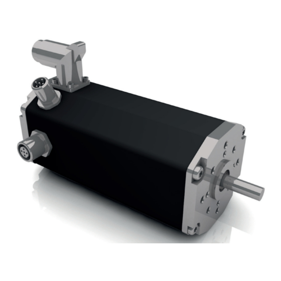
- Page 1 Original Funktions- und Anschlussbeschreibung/ Translation of the original function and connection guide BG 65 dMove / BG 66 dMove Typ: Part No: BG 65x25 dMove / BG 66x25 dMove 88565.14XXX / 88566.14XXX BG 65x50 dMove / BG 66x50 dMove 88565.15XXX / 88566.15XXX BG 65x75 dMove / BG 66x75 dMove 88565.16XXX / 88566.16XXX...
-
Page 2: Table Of Contents
Content Inhalt 1. About this Documentation ....5 1. Zu dieser Dokumentation...... 5 Liability and Warranty .......... 6 Haftung und Gewährleistung ....... 6 Target Group ............6 Zielgruppe ............6 Safety Notes ............6 Sicherheitshinweise ..........6 Further Icons ............7 Weitere Piktogramme .......... - Page 3 Optional Attachments ........15 Optionale Anbauten .......... 15 Functions ............16 Funktionen ............16 Type of control CANopen dMove CO ....17 Ansteuerungsvariante CANopen dMove CO ..17 Type of control dMove IO ........19 Ansteuerungsvariante dMove IO......19 Protective Functions .......... 20 Schutzfunktionen ..........
- Page 4 Protective Earth Conductor ....... 37 Schutzleiter ............37 Protective earthing ..........37 Schutzerdung ........... 37 Power and Logic Supply, Leistungs- und Logikversorgung, Inputs and Outputs ........... 38 Ein- und Ausgänge ........... 38 6.6.1 Power and Logic Supply, 6.6.1 Leistungs- und Logikversorgung, Ein- und Inputs and Outputs ...........
-
Page 5: About This Documentation
About this Documentation Zu dieser Dokumentation This documentation is targeted at people who are Diese Dokumentation richtet sich an Personen, die mit charged with transport, assembly and connection of the Transport, Montage und Anschluss des Motors beauftragt motor. sind. In the following, the BG 65 dMove and the BG 66 dMove Im nachfolgenden werden der BG 65 dMove und der is referred to as „product“. -
Page 6: Liability And Warranty
Liability and Warranty Haftung und Gewährleistung Dunkermotoren GmbH does not accept any liability or Die Dunkermotoren GmbH übernimmt keine Haftungs- warranty claims for personal injury or damage to property und Gewährleistungsansprüche für Personen- und Sach- if they are attributable to one or several of the following schäden, wenn sie auf einen oder mehrere der folgenden causes: Ursachen zurückzuführen sind:... -
Page 7: Further Icons
Further Icons Weitere Piktogramme This document uses the following icons: In diesem Dokument werden folgende Piktogramme ver- wendet: Symbol/ Meaning/ Symbol Bedeutung Observe operating instructions/ Gebrauchsanweisung beachten Earth before use/ Vor Benutzung erden Recommendations/ Empfehlungen Instruction to act/ Handlungsaufforderung Gefahrenzeichen Hazard Signs The hazard signs inform about potential hazards and Die Gefahrenzeichen weisen auf mögliche Gefahren hin... -
Page 8: Ec/Eu Declaration Of Conformity
EC/EU Declaration of Conformity EG/EU-Konformitätserklärung With the EC/EU declaration of conformity, the manufac- Mit der EG-/EU-Konformitätserklärung bescheinigt der turer confirms that he has met all basic safety and health Hersteller, alle grundlegenden Sicherheits- und Gesund- requirements of of the applicable directive. heitsanforderungen der anzuwendenden Richtlinie erfüllt zu haben. -
Page 9: Safety Notes
Safety Notes Sicherheitshinweise The safety notes are only part of the technical documen- Die Sicherheitshinweise sind nur ein Teil der technischen tation of this product. They must be read in connection Dokumentation dieses Produkts. Sie sind im Zusammen- with the other technical documentation. hang mit den anderen technischen Dokumentationen zu sehen. -
Page 10: Basic Safety Notes
Basic Safety Notes Grundlegende Sicherheitshinweise Only use the product in an impeccable condition. Verwenden Sie das Produkt nur im einwandfreien Zustand. Observe the technical data and environmental condi- tions indicated in the documentation. Halten Sie die in der Dokumentation angegebenen technischen Daten und Umgebungsbedingungen ein. -
Page 11: Safety Notes Concerning Operating Phases
Safety Notes concerning Operating Phases Sicherheitshinweise zu Betriebsphasen 2.5.1 Transport 2.5.1 Transport Transport the product contoller only in its original Transportieren Sie das Produkt nur in der Originalver- packaging. packung. Ensure that the transported goods are sufficiently Sorgen Sie für ausreichende Sicherung des Transport- secured. -
Page 12: Notes Concerning Special Hazard Types
Notes concerning Special Hazard Types Hinweise auf besondere Gefahrenarten 2.6.1 Electrical Energy/Electromagnetic 2.6.1 Elektrische Energie/elektromagnetische Safety Sicherheit Operation of the product or the entire equipment will Beim Betrieb des Produkts bzw. der gesamten Anlage produce electromagnetic interferences. These may influ- entstehen elektromagnetische Störungen. -
Page 13: Transport And Storage
Transport and Storage Transport und Lagerung Observe the environmental conditions during transport Beachten Sie bei Transport und Lagerung die Umge- and storage. If your storage and transport conditions bungsbedingungen. Falls Sie davon abweichende Lage- deviate from these (see table below), please contact us so rungs- und Transportbedingungen haben (siehe Tabelle that we can review potential impacts on your products. -
Page 14: Product Description
Product Description Produktbeschreibung Design Aufbau The BG 65/66 dMove motor series are brushless DC » Bei der Motorbaureihe BG 65/66 dMove handelt es » servomotors with integrated motion controllers. The sich um bürstenlose DC-Servomotoren mit integrier- tem Motioncontroller und komfortabler Bedienober- comfortable PC operating interface makes it easy to set drive parameters for a number of pre-installed fläche für PC, auf der sich die Antriebe für eine Reihe... -
Page 15: Starter Kit
Starter Kit Starter Kit The Motion Starter Kit is needed in order to integrate a Um einen Antrieb bzw. externen Regler über einen PC in drive unit or external controller into a CANopen network ein CANopen-Netzwerk als Slave zu integrieren, benötigt as a slave via a PC. -
Page 16: Functions
Functions Funktionen The BG 65/66 dMove is available with CO and IO functio- Der BG 65/66 dMove ist mit CO und IO Funktionalität nality. Information on this is available from Dunkermoto- erhältlich. Informationen dazu erhalten Sie bei Dunkermo- ren. toren. Various functions are available for any selected control: Unabhängig von der ausgewählten Ansteuerung stehen vielfältige Funktionen zur Verfügung:... -
Page 17: Type Of Control Canopen Dmove Co
Type of control CANopen dMove CO Ansteuerungsvariante CANopen dMove CO The communication protocol CANopen supports you Das Kommunikationsprotokoll CANopen unterstützt Sie in linking complex devices. In addition to the network bei der Vernetzung komplexer Geräte. Neben dem Netz- management and device monitoring, communication werkmanagement und der Geräteüberwachung wird auch between various nodes is supported as well. - Page 18 CANopen interfaces CANopen – Schnittstellen Profile Position Mode (CiA 402 Mode 1) Profile Position Mode (CiA 402 Mode 1) The „Profile Position Mode“ serves positioning from a start Der "Profile Position Mode" dient der Positionierung von to a target point. Positioning takes place with reference to einem Start- zu einem Zielpunkt.
-
Page 19: Type Of Control Dmove Io
Type of control dMove IO Ansteuerungsvariante dMove IO In IO mode, the product can be operated ‚stand-alone‘. Im IO Modus kann das Produkt ‚stand-alone‘ betrieben The product is then controlled via digital or analogue In- werden. Angesteuert wird das Produkt dann über digitale puts. -
Page 20: Protective Functions
Protective Functions Schutzfunktionen The product has various protection functions to avoid da- Das Produkt besitzt verschiedene Schutzfunktionen, um mage from overload. Each of these protection functions is Schäden durch Überbelastung zu vermeiden. Jede dieser described in detail below. The output stage switches off Schutzfunktionen wird nachfolgend im Detail beschrieben. -
Page 21: Current Limitation (I T)
4.8.4 Current Limitation (I 4.8.4 Strombegrenzung (I The products is protected from thermal overload by an Die Produkte sind durch einen I²t-basierten Algorithmus I²t-based algorithm. It calculates the heat supply caused gegen thermische Überlastung geschützt. Er berechnet by the phase current and limits the nominal current if die durch den Phasenstrom verursachte Wärmezufuhr the calculated product temperature exceeds the critical und begrenzt den Sollstrom, wenn die berechnete Tem-... - Page 22 Current characteristics BG 65 dMove Stromkennlinie BG 65 dMove Overload Characteristics (I²t) BG 65x25, 24V Overload Characteristics (I²t) BG 65x25, 48V 1000 1000 Motor Motor ‐20 ‐20 Phase Current [A] Phase Current [A] Overload Characteristics (I²t) BG 65x50, 48V Overload Characteristics (I²t) BG 65x50, 24V 1000 1000 Motor Motor ‐20 ‐20 Phase Current [A] Phase Current [A] Overload Characteristics (I²t) BG 65x75, 24V Overload Characteristics (I²t) BG 65x75, 48V 1000 1000 Motor Motor Temp [°C] ‐20 Phase Current [A]...
- Page 23 Current characteristics BG 66 dMove Stromkennlinie BG 66 dMove Overload Characteristics (I²t) BG 66x25, 24V Overload Characteristics (I²t) BG 66x25, 48V 1000 1000 Motor Motor ‐20 ‐20 Phase Current [A] Phase Current [A] Overload Characteristics (I²t) BG 66x50, 48V Overload Characteristics (I²t) BG 66x50, 24V 1000 1000 Motor Motor ‐20 ‐20 Phase Current [A] Phase Current [A] Overload Characteristics (I²t) BG 66x75, 48V 1000 Motor ‐20 Phase Current [A] Page/Seite 23 / 54 Version 15-02-2023 BG 65 dMove / BG 66...
-
Page 24: Ballast Circuit (Optional)
4.8.5 Ballast Circuit (optional) 4.8.5 Ballastschaltung (optional) The drive unit has a 4-quadrant control. Therefore, it can Der Antrieb besitzt eine 4-Quadranten Regelung, deshalb also work as a generator. During deceleration, the rotating kann er auch als Generator arbeiten. Beim Bremsen wird energy on the drive shaft is converted and fed back into die an der Antriebswelle vorhandene Energie umgewan- the power supply. -
Page 25: Voltage Controlled Braking
4.8.6 Voltage Controlled Braking 4.8.6 Spannungsgeregeltes Bremsen When the drive is actively braked, electrical energy flows Beim aktiven Abbremsen des Antriebes fließt elektrische back into the power supply. If this energy cannot be Energie zurück in die Stromversorgung. Kann diese absorbed, the voltage rises. -
Page 26: Technical Data
Technical Data Technische Daten Produktspezifikation BG 65 dMove Product specification BG 65 dMove Technical data/ BG 65x25 dMove BG 65x50 dMove BG 65x75 dMove Technische Daten Nominal voltage/ Nennspannung Nominal current/ Nennstrom Nominal torque/ 0,23 0,24 0,39 0,43 0,49 0,55 Nennmoment Nominal speed/ 4360... -
Page 27: Product Specification Bg 66 Dmove
Product specification BG 66 dMove Produktspezifikation BG 66 dMove Technical data/ BG 66x75 BG 66x25 dMove BG 66x50 dMove dMove Technische Daten Nominal voltage/ Nennspannung Nominal current/ 11,00 Nennstrom Nominal torque/ 0,26 0,34 0,38 0,53 0,55 0,75 Nennmoment Nominal speed/ 3950 3820 3600... -
Page 28: Electrical Data
Electrical Data Elektrische Daten BG 65/66 dMove 24 V 48 V Operating voltage range power supply/ 3 ... 58 3 ... 58 3 ... 58 Betriebsspannungsbereich Leistungsversorgung Operating voltage range logic supply/ 9 ... 30 Betriebsspannungsbereich Logikversorgung Max. permissible ripple supply Max. -
Page 29: Dimensional Drawing Bg 65 Dmove Co (With Can-Connector)
Dimensional Drawing BG 65 dMove CO Maßzeichnung BG 65 dMove CO (with CAN-connector) (mit CAN-Stecker) Motor/ Length L/ Motor Länge L BG 65x25 dMove 115±1 BG 65x50 dMove 140±1 BG 65x75 165±1 dMove Maßzeichnung BG 65 dMove IO Dimensional Drawing BG 65 dMove IO (ohne CAN-Stecker) (without CAN-connector) Motor/... -
Page 30: Dimensional Drawing Bg 66 Dmove Co (With Can-Connector)
Dimensional Drawing BG 66 dMove CO Maßzeichnung BG 66 dMove CO (with CAN-connector) (mit CAN-Stecker) Motor/ Length L/ Motor Länge L BG 66x25 dMove 115±1 BG 66x50 dMove 140±1 BG 66x75 dMove 165±1 Maßzeichnung BG 66 dMove IO Dimensional Drawing BG 66 dMove IO (ohne CAN-Stecker) (without CAN-connector) Motor/... -
Page 31: Shaft Load Chart
Shaft load chart Wellenbelastungsdiagramm NOTICE ACHTUNG Motor damage Motorschaden The permissible shaft loads (axial/radial) depend on the Die zulässigen Wellenbelastungen (axial/radial) sind speed. Observe the following chart for this. The motor abhängig von der Drehzahl. Beachten Sie hierzu das may fail early if overloaded. nachfolgende Diagramm. -
Page 32: Motor Label
5.10 Motor label 5.10 Typenschild Description/ Position Bezeichnung Drive Components/ Antriebskomponenten Nominal voltage/ Nennspannung Material number/ Materialnummer Customer line (max. 30 characters)/ Kundenzeile (max. 30 Zeichen) MAC Address/ MAC Adresse Nominal speed/ Nenndrehzahl UL insulation system/ UL-Isolationssystem Production Date (CW/Year)/ Produktionsdatum (KW/Jahr) Data Matrix Code for the drive specification in App Data Matrix Code für die Antriebsspezifikationen in der App... -
Page 33: Installation
Installation Installation The safety notes must be read and ob- Vor der Inbetriebnahme sind unbedingt served before commissioning. Non-ob- die Sicherheitshinweise zu lesen und zu servation may cause danger to people beachten. Eine Nichtbeachtung kann or damage to the machine. zu Gefahren für Personen oder Be- schädigungen an der Maschine führen. -
Page 34: Mechanical Assembly
Mechanical Assembly Mechanische Montage NOTICE ACHTUNG Short circuit Kurzschluss Bent connector pins can destroy the drive unit by short Umgebogene Stecker-Pins können den Antrieb durch circuit. Kurzschluss zerstören. Ensure that the connectors are not damaged during Achten Sie bei der Installation darauf, dass die installation. -
Page 35: Electrical Assembly
Electrical Assembly Elektrische Montage WARNING WARNUNG Injury and product damage from Personen- und Produktschaden durch electrical voltages elektrische Spannungen The safety notes must be read and Vor der Inbetriebnahme sind unbedingt observed before commissioning. Non-ob- die Sicherheitshinweise zu lesen und zu servation may cause danger to people or beachten. -
Page 36: Emc Compliant Installation
EMC compliant installation EMV-konforme Installation WARNING WARNUNG High-frequency interference Hochfrequente Störungen (radio interference) (Funkstörungen) If the motor/control electronics are not Wird der Motor nicht entsprechend den installed accordingly the instructions in Anweisungen in Betrieb genommen und operation, it can create Interference with verwendet, kann es zu Störungen von radio transmission. -
Page 37: Protective Earth Conductor
Shielding (Functional Erth) Schirmung (Funktionserde) Note that protection from influence by Beachten Sie, dass ohne Erdung des electromagnetic fields is not provided if Schirms ein Schutz gegen Beeinflus- the shield is not earthed. sung durch elektromagnetische Felder nicht gegeben ist. Connect the shield at each cable end to system Schirm an jedem Leitungsende gegen Anlagenerde ground over a large area. -
Page 38: Power And Logic Supply
Power and Logic Supply, Leistungs- und Logikversorgung, Inputs and Outputs Ein- und Ausgänge 6.6.1 Power and Logic Supply, 6.6.1 Leistungs- und Logikversorgung, Ein- und Inputs and Outputs Ausgänge NOTICE ACHTUNG Short circuit Kurzschluss Bent connector pins can destroy the drive unit by short Umgebogene Stecker-Pins können den Antrieb durch circuit. - Page 39 Connection via 12+3-pin connector for motor Anschluss über 12+3-poligen Stecker für Motor This pin assignment is the standard pin Bei dieser Pinbelegung handelt es sich assignment. Leading is the pin assi- um die Standard-Belegung. Führend ist gnment shown in the motor drawing. die auf der Motorzeichnung angegebe- ne Pinbelegung.
- Page 40 Angle Position Power Supply Winkelposition Leistungsversorgung NOTICE ACHTUNG Short circuit Kurzschluss Rotation of the connector over an angle of +45°/ 180°, Verdrehen des Anschlußsteckers über einen Drehwin- kel von +45°/ 180°, wenn der Stecker in Richtung Ab- if the plug faces in the direction of the output shaft triebswelle zeigt, bzw.
-
Page 41: Mating Connector With Connection Cable
6.6.2 Mating Connector with Connection Cable 6.6.2 Gegenstecker mit Anschlussleitung Matching pre-fabricated connection cables are available Für die Produkte mit 12+3-poligem Anschlussstecker for the products with a 12+3-pin connector. stehen passende, vorkonfektionierte Anschlussleitungen zur Verfügung. Different cable lengths are available ex stock: Verschiedenen Leitungslängen sind ab Lager verfügbar: Cable length L/ Order number/... -
Page 42: Power And Logic Supply, Inputs And Outputs (Legacy)
Power and Logic Supply, Leistungs- und Logikversorgung, Inputs and Outputs (legacy) Ein- und Ausgänge (legacy) NOTICE ACHTUNG Short circuit Kurzschluss Bent connector pins can destroy the drive unit by short Umgebogene Stecker-Pins können den Antrieb durch circuit. Kurzschluss zerstören. Ensure that the connectors are not damaged during Achten Sie bei der Installation darauf, dass die installation. - Page 43 Connection via 15-pin connector for motor Anschluss über 15-poligen Stecker für Motor This pin assignment is the standard pin Bei dieser Pinbelegung handelt es sich assignment. Leading is the pin assi- um die Standard-Belegung. Führend ist gnment shown in the motor drawing. die auf der Motorzeichnung angegebe- ne Pinbelegung.
-
Page 44: Connector With Cable, 15 Pin
6.7.1 Connector with Cable, 15 pin 6.7.1 Anschlussleitung mit Dose, 15-polig Matching pre-fabricated connection cables are available Für die Motoren BG 65/66 dMove mit 12+3-poligem for the motors BG 65/66 dMove with a 12+3-pin connec- Anschlussstecker stehen passende, vorkonfektionierte tor. Anschlussleitungen zur Verfügung. -
Page 45: Canopen Fieldbus Connection (Only For Co Versions)
CANopen Fieldbus Connection CANopen-Feldbusanschluss (only for CO versions) (nur für CO Versionen) The CANopen interface and the connectors used corre- Die CANopen Schnittstelle und die verwendeten Steck- spond to the CiA 303-1-standard. This standard contains verbinder entsprechen dem CiA 303-1-Standard. In all notes necessary for wiring, topology and cable lengths. -
Page 46: Canopen Mating Connector With Connection Cable (Only For Co Versions)
6.8.1 CANopen Mating Connector with Connection 6.8.1 CANopen-Gegenstecker mit Anschlussleitung Cable (only for CO versions) (nur für CO Versionen) Matching pre-fabricated connection cables are available Für die Produkte mit CANopen Anschlussstecker stehen for the products with a CANopen connector. passende, vorkonfektionierte Anschlussleitungen zur Ver- fügung. -
Page 47: Power Supply Connection
Power Supply Connection Anschluss Spannungsversorgung NOTICE ACHTUNG Destruction of the electronics Zerstörung der Elektronik If several drive units are wired together, the summa- Bei gemeinsamer Verdrahtung mehrerer Antriebe ist die tion of the activation and starting currents must be Summierung von Einschalt- und Anlaufströmen zu be- observed. -
Page 48: Circuit Diagram For Bg 65/66 Dmove Motors
6.9.1 Circuit Diagram for BG 65/66 dMove Motors 6.9.1 Schaltplan für BG 65/66 dMove Motors Wiring BG65 / 66 dMove drives Communication hybrid from control unit (optional) connector (only CO version) IN 0 example: connection IN 1 of a switch/sensor IN 2 example: signal IN 3... -
Page 49: Starter Kit For Dmove And Dpro Io/Co
6.10 Starter Kit for dMove and dPro IO/CO 6.10 Starter Kit für dMove und dPro IO/CO The starter kit establishes a connection between the Mit dem Starter Kit wird eine Verbindung zwischen dem commissioning computer and the motor electronics. This Inbetriebnahme-Rechner und der Motorelektronik her- allows dMove and dPro CO and IO products to be exten- gestellt. -
Page 50: Principle Circuit Diagram Of Digital Inputs
6.11 Principle Circuit Diagram of Digital Inputs 6.11 Prinzipschaltbild Digitaleingänge IN X GND Logic digital input, internal circuit digital input R in [Ohms] high standard op�on <5.0 >15.0 15.4k -3.0 12V op�on 18.9k -3.0 <2.5 >8.0 6.12 Principle Circuit Diagram of Analogue Inputs 6.12 Prinzipschaltbild Analogeingänge R in... -
Page 51: Maintenance
Maintenance Wartung WARNING WARNUNG Injury Personenschaden The drive units may move unexpectedly Trotz laufender Instandhaltung oder War- in spite of continuous maintenance or tung, können sich die Antriebe unerwartet servicing, since third parties may start bewegen, da diese durch Dritte in Be- them up. -
Page 52: Service And Support
Service and Support Service und Support The following contacts will answer your questions and Bei Fragen und Problemen stehen Ihnen folgende An- help you with any issues: sprechpartner zur Verfügung: Your competent representation. Ihre zuständige Vertretung. » » » Your competent Dunkermotoren Key Account Mana- »... -
Page 53: Imprint
Imprint Impressum Version 15-02-2023 Version 15-02-2023 Creation date: February 2023 Erstelldatum: Februar 2023 Dunkermotoren GmbH Dunkermotoren GmbH Allmendstrasse 11 Allmendstrasse 11 D-79848 Bonndorf D-79848 Bonndorf Phone: +49 (0) 77 03/930-0 Telefon: 0 77 03/930-0 Fax: +49 (0) 77 03/930-210 Fax: 0 77 03/930-210 E-Mail: info@dunkermotoren.de E-Mail:... - Page 54 Dunkermotoren GmbH | Allmendstr. 11 | D-79848 Bonndorf/ Schwarzwald Phone +49 (0) 7703 930-0 | Fax +49 (0) 7703 930-210/ 212 | info@dunkermotoren.de...
Need help?
Do you have a question about the dunkermotoren BG 65 dMove Series and is the answer not in the manual?
Questions and answers