Table of Contents
Advertisement
Quick Links
Original Funktions- und Anschlussbeschreibung/
Translation of the original function and connection guide
Servo Linear SL 38 A / C / STL
Typ:
SL 38x06 A / SL 38x10 A / SL 38x14 A
SL 38x06 C / SL 38x10 C / SL 38x14 C
RC38-XXXX
SL 38x06 STL/ SL 38x10 STL / SL 38x14 STL
Part No:
91610.XXXXX
91620.XXXXX
91620.XXXXX
91680.XXXXX
Advertisement
Table of Contents

Related Manuals for Ametek dunkermotoren SL 38 A Series


Summary of Contents for Ametek dunkermotoren SL 38 A Series
- Page 1 Original Funktions- und Anschlussbeschreibung/ Translation of the original function and connection guide Servo Linear SL 38 A / C / STL Typ: Part No: SL 38x06 A / SL 38x10 A / SL 38x14 A 91610.XXXXX SL 38x06 C / SL 38x10 C / SL 38x14 C 91620.XXXXX RC38-XXXX 91620.XXXXX...
-
Page 2: Table Of Contents
Content Inhalt 1. About this Documentation ....5 1. Zu dieser Dokumentation...... 5 Liability and Warranty .......... 6 Haftung und Gewährleistung ....... 6 Target Group ............6 Zielgruppe ............6 Safety Notes ............6 Sicherheitshinweise ..........6 Icons ..............7 Piktogramme ............ - Page 3 Mechanical Specifications ......... 20 Mechanische Daten .......... 20 Environmental Conditions ........20 Umgebungsbedingungen ........20 5.4.1 Motor dimensioning – Software “ThrustCalc” ..21 5.4.1 Motorauslegung - Software „ThrustCalc“ ... 21 Characteristic diagrams SL 38 A ....... 22 Kennlinien SL 38 A ..........22 Characteristic diagrams SL 38 C .......
- Page 4 EMV compliant installation......... 52 EMV-konforme Installation ......... 52 6.3.1 Functional Earth ..........53 6.3.1 Funktionserde ........... 53 Power and Logic Supply SL 38 A / C, Leistungs- und Logikversorgung SL 38 A / C, Inputs and Output ..........54 Ein- und Ausgänge ........... 54 6.4.1 Power Supply, Inputs and Output ......
-
Page 5: About This Documentation
About this Documentation Zu dieser Dokumentation This documentation is targeted at people who are Diese Dokumentation richtet sich an Personen, die mit charged with transport, assembly and connection of the Transport, Montage und Anschluss des Produkts beauf- product. tragt sind. In the following, the Servo Linear is referred to as „pro- Im nachfolgenden wird der Servo Linear als „Produkt“... -
Page 6: Liability And Warranty
Liability and Warranty Haftung und Gewährleistung Dunkermotoren GmbH does not accept any liability or Die Dunkermotoren GmbH übernimmt keine Haftungs- warranty claims for personal injury or damage to property und Gewährleistungsansprüche für Personen- und Sach- if they are attributable to one or several of the following schäden, wenn sie auf einen oder mehrere der folgenden causes: Ursachen zurückzuführen sind:... -
Page 7: Icons
Piktogramme Icons This document uses the following icons: In diesem Dokument werden folgende Piktogramme ver- wendet: Symbol/ Meaning/ Symbol Bedeutung Observe operating instructions/ Gebrauchsanweisung beachten Earth before use/ Vor Benutzung erden Recommendations/ Empfehlungen Instruction to act/ Handlungsaufforderung Hazard Signs Gefahrenzeichen The hazard signs inform about potential hazards and Die Gefahrenzeichen weisen auf mögliche Gefahren hin name measures to avoid risks. -
Page 8: Ec/Eu Declaration Of Conformity
EC/EU Declaration of Conformity EG/EU-Konformitätserklärung With the EC/EU declaration of conformity, the manufac- Mit der EG-/EU-Konformitätserklärung bescheinigt der turer confirms that he has met all basic safety and health Hersteller, alle grundlegenden Sicherheits- und Gesund- requirements of of the applicable directive. heitsanforderungen der anzuwendenden Richtlinie erfüllt zu haben. -
Page 9: Safety Notes
Sicherheitshinweise Safety Notes The safety notes are only part of the technical documen- Die Sicherheitshinweise sind nur ein Teil der technischen tation of this product. They must be read in connection Dokumentation dieses Produkts. Sie sind im Zusammen- with the other technical documentation. hang mit den anderen technischen Dokumentationen zu sehen. -
Page 10: Basic Safety Notes
Basic Safety Notes Grundlegende Sicherheitshinweise Only use the product in an impeccable condition. Verwenden Sie das Produkt nur im einwandfreien Zustand. Observe the technical data and environmental condi- tions indicated in the documentation. Halten Sie die in der Dokumentation angegebenen technischen Daten und Umgebungsbedingungen ein. -
Page 11: Safety Notes Concerning Operating Phases
Sicherheitshinweise zu Betriebsphasen Safety Notes concerning Operating Phases 2.5.1 Transport 2.5.1 Transport Transport the product contoller only in its original Transportieren Sie das Produkt nur in der Originalver- packung. packaging. Sorgen Sie für ausreichende Sicherung des Transport- Ensure that the transported goods are sufficiently secured. -
Page 12: Maintenance/Repair
2.5.4 Maintenance/Repair 2.5.4 Wartung/Reparatur The product SL 38 C is maintenance-free during the Das Produkt SL 38 C ist über die vorhergesehene Le- intended service life. bensdauer wartungsfrei. With the SL 38 A, only the two slide bearings need to be Beim SL 38 A müssen, sofern notwendig, lediglich die replaced, if necessary. -
Page 13: Notes Concerning Special Hazard Types
Notes concerning Special Hazard Types Hinweise auf besondere Gefahrenarten 2.6.1 Electrical Energy/Electromagnetic 2.6.1 Elektrische Energie/elektromagnetische Safety Sicherheit Operation of the product or the entire equipment will Beim Betrieb des Produkts bzw. der gesamten Anlage produce electromagnetic interferences. These may influ- entstehen elektromagnetische Störungen. -
Page 14: Transport And Storage
Transport und Lagerung Transport and Storage Observe the environmental conditions during transport Beachten Sie bei Transport und Lagerung die Umge- and storage. If your storage and transport conditions bungsbedingungen. Falls Sie davon abweichende Lage- deviate from these (see table below), please contact us so rungs- und Transportbedingungen haben (siehe Tabelle that we can review potential impacts on your products. - Page 15 Storage and transport conditions/ Long-term/ Temporary (24h)/ Lagerungs- und Transportbedingungen Dauerhaft Kurzzeitig (24h) Temperature range/ °C -5 ... +55 - 25 ... +70 Temperaturbereich Relative humidity (non-condensing)/ 30 ... 70 Relative Luftfeuchtigkeit (nicht kondensierend) Recommended storage time/ < 2 years/ <...
-
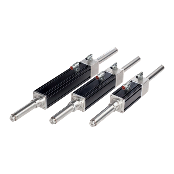
Page 16: Product Description
Produktbeschreibung Product Description Design Aufbau The Servo Linear SL 38 is a highly dynamic 3-phase Der Servo Linear SL 38 ist ein hochdynamischer » » linear motor. It includes an IP65 forcer and a sealed 3-Phasen Linearmotor. Er beinhaltet eine IP65 Primär- thrust rod (rare earth magnets) made of stainless steel. - Page 17 Description/ Position Bezeichnung Motor feedback/ Motorfeedback Connection for motor feedback/ Anschluss für Motorfeedback Connections for water cooling/ Anschlüsse für Wasserkühlung Thrust rod/ Magnetstange Slide bearing front/ Gleitlager vorne Connection for motor phases incl. temperature sensor/ Anschluss für Motorphasen inkl. Temperatursensor Forcer/ Primäreinheit Version 2.0 / 26-06-2024...
- Page 18 Bestellnummer Actuator: Actuator Actuator order number: Actuator Component order number: Comonent + RC 38 Bestellnummer Komponente: Komponente + RC 38 Actuator Component SL38x Forcer RA stroke Size RA max. stroke in mm 06, 10 & 14 020, *045, 071, *097, 122, *148, Version 173, *199, 225, *250, 276, *302, C - Component...
-
Page 19: Technical Data
Technische Daten Technical Data Produktspezifikation Product specification Technical data/ SL 38x06 A / C SL 38x10 A / C SL 38x14 A / C Technische Daten Nominal voltage/ Nennspannung Peak current/ Spitzenstrom Peak force/ 1581 2285 2637 2214 3690 Spitzenkraft Nominal current (w/o water cooling)/ Nennstrom (ohne Wasserkühlung) Nominal force (w/o water cooling)/... -
Page 20: Thermal Specifications
Thermal Specifications Thermische Daten Preliminary Technical data/ SL 38x06 A / C SL 38x10 A / C SL 38x14 A / C Technische Daten vorläufig Maximum phase temperature/ °C Maximale Phasen-Temperatur Power dissipation Water Cooled/ Verlustleistung wassergekühlt Power dissipation Non Water Cooled/ Verlustleistung nicht-wassergekühlt Mechanical Specifications Mechanische Daten... -
Page 21: Motor Dimensioning - Software "Thrustcalc
5.4.1 Motor dimensioning – Software “ThrustCalc” 5.4.1 Motorauslegung - Software „ThrustCalc“ The „ThustCalc“ software can be used to reliably design a Mit der Software „ThustCalc“ können verschiedenste An- wide range of applications. Dunkermotoren will be happy wendungsfälle zuverlässig auslegen werden. Gerne unter- to assist you with the design of your application. -
Page 22: Characteristic Diagrams Sl 38 A
Characteristic diagrams SL 38 A Kennlinien SL 38 A Diagrams are calculated from specifica- Diagramme werden aus Spezifikations- tion data. The individual application can daten berechnet. Der einzelne Anwen- be calculated with the software „Thrust- dungsfall kann mit der Software „Thrust Calc“. -
Page 23: Characteristic Diagrams Sl 38 C
Characteristic diagrams SL 38 C Kennlinien SL 38 C Diagrams are calculated from specifica- Diagramme werden aus Spezifikations- tion data. The individual application can daten berechnet. Der einzelne Anwen- be calculated with the software „Thrust- dungsfall kann mit der Software „Thrust Calc“. -
Page 24: Dimensional Drawing Servo Linear Sl 38 A
Maßzeichnung Servo Linear SL 38 A Dimensional Drawing Servo Linear SL 38 A SL 38 A SL 38x14 A 530.6 SL 38x10 A 428.2 SL 38x06 A 325.8 Page/Seite 24 / 74 Servo Linear SL 38 A / C / STL Version 2.0 / 26-06-2024... -
Page 25: Stroke Length
5.7.1 Stroke length 5.7.1 Hublänge Stroke Servo Linear SL 38 A Length L (in mm)/ SL 38x06 A SL 38x10 A SL 38x14 A Länge L (in mm) On request/ Auf Anfrage Version 2.0 / 26-06-2024 Servo Linear SL 38 A / C / STL Page/Seite 25 / 74... -
Page 26: Dimensional Drawing Servo Linear Sl 38 C
Dimensional Drawing Servo Linear SL 38 C Maßzeichnung Servo Linear SL 38 C SL 38 C SL 38x14 C 462.8 SL 38x10 C 360.2 SL 38x06 C 257.8 = 385 to 2000 Page/Seite 26 / 74 Servo Linear SL 38 A / C / STL Version 2.0 / 26-06-2024... -
Page 27: Notes About The Thrust Rod
5.8.1 Notes about the thrust rod 5.8.1 Hinweise zur Magnetstange The thrust rod comprises a thin walled stainless steel tube Die Magnetstange besteht aus einem dünnwandigen containing high-energy permanent magnet pieces. The Edelstahlrohr mit hochenergetischen Permanentmagnet- components within the assembled thrust rod are potted stücken. -
Page 28: Rod Length
5.8.2 Rod Length 5.8.2 Länge Magnetstange Rod Servo Linear SL 38 C Rod Length L (in mm)/ SL 38x06 C SL 38x10 C SL 38x14 C Magnetlänge L (in mm) 1205 1615 1231 1641 1256 1667 1282 1692 1308 1718 1333 1744 1359... -
Page 29: Motor Feedback (Linear Encoder)
Motor feedback (linear encoder) Motorfeedback (Linearencoder) The position sensor outputs analogue, differential sine Als Positionsrückmeldung gibt der integrierte Lagegeber and cosine signals for providing position feedback. Figure analoge Sinus und Cosinus Signale als Differenzsignale C.1 shows the relationships between forcer phase back aus. - Page 30 Servo Linear SL 38 Output signal period/ 51.2 Ausgangssignal-Periode Signal amplitude (between +/- signal)/ Vpk-pk Signal Amplitude (zw. +/- Signal) Output current/ ±10 Ausgangsstrom Supply voltage/ V d.c. 5 ± 0.25 Versorgungsspannung Supply current (output current =0)/ 70 ± 10 Versorgungsstrom (Ausgangsstrom =0) Resolution micron...
-
Page 31: Forcer Temperature Sensor
5.10 Forcer temperature sensor 5.10 Primäreinheit Temperatursensor NOTICE ACHTUNG Overheating of the forcer Überhitzung der Primäreinheit High temperatures can cause damage at the forcer. Hohe Temperaturen können zu Schäden an der Primär- einheit führen. Connect the forcer temperature sensor to the drive amplifier or servo controller at all times. -
Page 32: Motor Label
5.11 Motor label 5.11 Typenschild 5.11.1 Main type plate 5.11.1 Haupttypenschild SL38x13 A 91110.00320 560 VDC CI.A 35/22 xx A Cant. Stall Current 5.12 A 5XXXXXXX Kundenzeile Description/ Position Bezeichnung Material number)/ Materialnummer Nominal Voltage/ Nennspannung Nominal current/ Nennstrom Cont. Stall Current/ Spitzenstrom Serial number Seriennummer... -
Page 33: Motor Label
5.12 Motor label 5.12 Typenschild 5.12.1 Serial number type label 5.12.1 Serialnummerntypenschild Description/ Position Bezeichnung Material number/ Materialnummer Serial number Seriennummer Version 2.0 / 26-06-2024 Servo Linear SL 38 A / C / STL Page/Seite 33 / 74... -
Page 34: Installation
Installation Installation The safety notes must be read and ob- Vor der Inbetriebnahme sind unbedingt served before commissioning. Non-ob- die Sicherheitshinweise zu lesen und zu servation may cause danger to people beachten. Eine Nichtbeachtung kann zu or damage to the product. Gefahren für Personen oder Beschädi- gungen am Produkt führen. -
Page 35: Mechanical Assembly
Mechanical Assembly Mechanische Montage WARNING WARNUNG Pacemaker malfunction Störung des Herzschrittmachers Magnets can influence the function of Magnete können die Funktion von Herz- pacemakers and implanted defibrillators. schrittmachern und implantierten Defibril- A pacemaker can be switched to test latoren beeinflussen. Ein Herzschrittma- mode and cause discomfort. - Page 36 CAUTION VORSICHT Further moving of the motor Nachlaufender Antrieb If the power supply, the control or regula- Bei Ausfall der Energieversorgung, des tion circuit fails, or if the drive is stopped Steuer-, bzw. Regelkreises, sowie durch by an emergency stop, the drive can con- das Stillsetzen durch Not-Aus kann der tinue to move.
- Page 37 NOTICE ACHTUNG Loose or overloaded screw connections Lose oder überlastete Schraubverbindungen When mounting the product in the system, loose or Bei der Montage des Produkts in die Anlage können overloaded screw connections can cause damage to durch lose oder überlastete Schraubenverbindungen the product, as can faulty assembly of the product.
-
Page 38: Unpacking The Product
6.1.1 Unpacking the product 6.1.1 Produkt auspacken WARNING WARNUNG Strong attractive forces Starke Anziehungskräfte Thrust rods contain strong magnets that Magnetstangen enthalten starke Mag- attract or are attracted to e. g. ferrous nete, die z. B. eisenhaltige Materialien materials. If handled carelessly, persons anziehen oder davon angezogen werden. -
Page 39: Mechanical Assembly Sl 38 A
6.1.2 Mechanical Assembly SL 38 A 6.1.2 Mechanische Montage SL 38 A Anbauteile an der vorderen und hinte- Attachments on the front and rear sides ren Seite der Primäreinheit müssen aus of the forcer must be made of non-fer- Nichteisenmetallen, wie zum Beispiel rous metals such as aluminium or stain- Aluminium oder Edelstahl sein. -
Page 40: 6.1.2.1 Mounting The Forcer
6.1.2.1 Primäreinheit montieren 6.1.2.1 Mounting the forcer In the entire circumference of the housing there are Im gesamten Umfang des Gehäuses befinden sich T-Nu- T-slots, which are used for mounting the forcer. For the ten, welche zur Montage der Primäreinheit dienen. Für grooves, DIN508 M5x6 T-slot nuts in stainless steel must die Nuten sind Nutensteine DIN 508 M5x6 in Edelstahl zu be used. -
Page 41: Mounting The Rod Ra 38
6.1.2.2 Magnetstange RA 38 montieren 6.1.2.2 Mounting the rod RA 38 WARNING WARNUNG Strong attractive forces Starke Anziehungskräfte Magnetstangen enthalten starke Mag- Thrust rods contain strong magnets that attract or are attracted to e. g. ferrous nete, die z. B. eisenhaltige Materialien anziehen oder davon angezogen werden. -
Page 42: Mechanical Assembly Sl 38 C
6.1.3 Mechanical Assembly SL 38 C 6.1.3 Mechanische Montage SL 38 C Attachments on the front and rear sides Anbauteile an der vorderen und hinteren of the forcer and the thrust rod must Seite der Primäreinheit sowie Magnet- be made of non-ferrous metals such as stange müssen aus Nichteisenmetallen, aluminium or stainless steel. -
Page 43: 6.1.3.1 Mounting The Forcer
6.1.3.1 Mounting the forcer 6.1.3.1 Primäreinheit montieren Im gesamten Umfang des Gehäuses befinden sich T-Nu- In the entire circumference of the housing there are T-slots, which are used for mounting the forcer. For the grooves, ten, welche zur Montage der Primäreinheit dienen. Für die Nuten sind Nutensteine DIN 508 in Edelstahl zu verwen- DIN508 T-slot nuts in stainless steel must be used. -
Page 44: Mounting The Thrust Rod Rc 38
6.1.3.2 Mounting the thrust rod RC 38 6.1.3.2 Magnetstange RC 38 montieren WARNING WARNUNG Strong attractive forces Starke Anziehungskräfte Thrust rods contain strong magnets that Magnetstangen enthalten starke Mag- attract or are attracted to e. g. ferrous nete, die z. B. eisenhaltige Materialien materials. -
Page 45: Mounting The Water Cooling
6.1.4 Mounting the water cooling 6.1.4 Wasserkühlung montieren Um die Wasserkühlung zu nutzen entfernen Sie die To use the water cooling remove the screws Schrauben Then mount the M7 screw-in connection or iden- Anschließend montieren Sie den M7 Einschraub- tical in construction. If you have your own connection, ensure that it is leak-proof. -
Page 46: Electrical Assembly
Electrical Assembly Elektrische Montage WARNING WARNUNG Injury damage from moving compo- Personenschaden durch bewegte nents Bauteile Retraction or grasp of body parts or Durch das Einziehen oder Erfassen von clothes, as well as friction or abrasion on Körperteilen oder Kleidungsstücken, moving components can cause serious sowie durch Reibungen oder Abschür- injuries. - Page 47 WARNING WARNUNG Uncontrolled movements after Unkontrollierte Bewegungen nach emergency stop Not-Aus At shutdown due to emergency stop or Beim Stillsetzen durch Not-Aus oder when stopping by safety inputs Ena- beim Stillsetzen durch Sicherheitsein- ble 1/Enable 2 for STO, power supply gänge Enable 1/Enable 2 für STO, dem failure, control circuit failure, control Ausfall der Energieversorgung oder des...
- Page 48 CAUTION VORSICHT Avoid ground loops Erdungsschleifen vermeiden Loops must be avoided for all grounding Grundsätzlich sind bei allen Erdungs- concepts. The drive may be destroyed. konzepten Schleifen zu vermeiden. Der Antrieb kann zerstört werden. The power supply cable must be as short as possible.
- Page 49 NOTICE ACHTUNG Short circuit Kurzschluss Bent connector pins can destroy the product by short Umgebogene Stecker-Pins können das Produkt durch circuit. Kurzschluss zerstören. Ensure that the connectors are not damaged during Achten Sie bei der Installation darauf, dass die installation. Steckverbinder nicht beschädigt werden.
- Page 50 This equipment must be earthed using Das Gerät muss mit Hilfe des grün/gel- the green/yellow conductor. ben elektrischen Erdungsleiters geerdet werden. Check the specifications on the type plate and ensure Überprüfen Sie die technischen Angaben auf dem the applicability between operating requirement and Typenschild und stellen Sie sicher, dass die Leistungs- label data fähigkeit des Antriebs die aus der Applikation resultie-...
-
Page 51: Cable
6.2.1 Cable 6.2.1 Kabeltyp The SL 38 series has two separate cables providing Die SL 38 Reihe hat zwei getrennte Verbindungskabel connections for motor phases and motor feedback. The für die Motorphasen und den Motorfeedback. Die erhält- standard cables supplied are flexible and intended for lichen Standardkabel sind flexibel, und für Schleppketten- continuous flex or drag chain applications. -
Page 52: Emv Compliant Installation
EMV compliant installation EMV-konforme Installation NOTICE ACHTUNG High-frequency interference Hochfrequente Störungen (radio interference) (Funkstörungen) If the products are not installed accordingly the instruc- Wird das Produkt nicht entsprechend den Anweisun- tions in operation, it can create Interference with radio gen in Betrieb genommen und verwendet, kann es zu transmission. -
Page 53: Functional Earth
6.3.1 Functional Earth 6.3.1 Funktionserde Note that protection from influence by Beachten Sie, dass ohne Erdung des electromagnetic fields is not provided if Schirms ein Schutz gegen Beeinflus- the shield is not earthed. sung durch elektromagnetische Felder nicht gegeben ist. Connect the shield at each cable end to system Schirm an jedem Leitungsende gegen Anlagenerde ground over a large area. -
Page 54: Power And Logic Supply Sl 38 A / C, Inputs And Output
Power and Logic Supply SL 38 A / C, Leistungs- und Logikversorgung SL 38 A / C, Inputs and Output Ein- und Ausgänge 6.4.1 Power Supply, Inputs and Output 6.4.1 Leistungsversorgung, Ein- und Ausgänge The 8-pin motor connector serves to supply the motor Der 8-polige Motorstecker dient zur Leistungsversorgung with power. -
Page 55: Mating Connector Power Supply (With Cabel)
6.4.3 Mating Connector Power Supply 6.4.3 Gegenstecker Leistungsversorgung (with cabel) (mit Kabel) The 8-pin motor connector serves to supply the motor Der 8-polige Motorstecker dient zur Leistungsversorgung with power. des Motors. Matching pre-fabricated connection cables are available Für die Motoren mit 8-poligem Anschlussstecker stehen for the motors with a 8-pin connector. -
Page 56: Logic Supply, Inputs And Outputs
6.4.4 Logic Supply, Inputs and Outputs 6.4.4 Logikversorgung, Ein- und Ausgänge The 17-pole motor connector is used for logic supply and Der 17-polige Motorstecker dient zur Logikversorgung outputs the sine and cosine encoder signals. und gibt die Sinus- und Cosinus-Gebersignale aus. Round connector Rundstecker Intercontec series 617 Intercontec series 617... -
Page 57: Mating Connector Power Supply (With Cabel)
6.4.6 Mating Connector Power Supply 6.4.6 Gegenstecker Logikversorgung (with cabel) (mit Kabel) Matching pre-fabricated connection cables are available Für Motoren mit 17-poligem Anschlussstecker stehen for the motors with a 17-pin connector. passende, vorkonfektionierte Anschlussleitungen zur Ver- fügung. To properly attach the connection cable to the plug, plea- Um das Anschlusskabel ordnungsgemäß... -
Page 58: Angle Position Motor Connector
Angle Position Motor Connector Winkelposition Motorstecker NOTICE ACHTUNG Short circuit Kurzschluss Twisting the connector plugs beyond a rotation angle Verdrehen der Anschlussstecker über einen Drehwin- of -100°/+170° and -230°/+100°can lead to a short kel von -100°/+170° und -230°/+100° hinaus kann zu circuit, body short or a malfunction due to loosened Kurzschluss, Körperschluss oder einer Fehlfunktion strands at the screw points. -
Page 59: Connecting Motor To Connection Cable
Connecting Motor to Connection Cable Motor mit Anschlusskabel verbinden Remove the O-ring on the motorised plug before plugging Beim Stecker Typ Speedtec (Überwurfmutter Schnell Ver- in the Speedtec type plug (quick-release union nut). IP schluss) den O-Ring, am Motorstecker, vor dem einste- protection is retained. -
Page 60: Power And Logic Supply Sl 38Stl, Inputs And Output
Power and Logic Supply SL 38STL, Leistungs- und Logikversorgung SL 38 STL, Inputs and Output Ein- und Ausgäng 6.7.1 Power Supply 6.7.1 Leistungsversorgung The 4-lead power cable is used for power supply and Das 4-adrige Leistungskabel dient zur Leistungsversor- earthing the motor. gung und Erdung des Motors. -
Page 61: Connection Sl38-Pollmeier Dme
Connection SL38-Pollmeier DME Anschluss SL38-Pollmeier DME To connect the SL38 with a DME230 or DME400, the Um den SL38 mit einem DME230 oder DME400 zu ver- following connection logic results on the controller side. binden ergibt sich folgende Anschlusslogik auf Regler- seite. -
Page 62: Connector Power Supply
6.8.2 Connector Power Supply 6.8.2 Stecker Leistungsversorgung The power cable is divided between two connector strips Das Leistungskabel wird am Regler auf zwei Steckerleis- on the controller. The temperature sensor is applied to ten aufgeteilt. Der Temperatursensor wird am Anschluss PIN 3 and 4 at connection X2. -
Page 63: Maintenance
Wartung Maintenance The basic safety notes must be read Vor der Wartung sind unbedingt die grundlegenden Sicherheitshinweise zu and observed before maintenance. Non-observation may cause danger to lesen und zu beachten. Eine Nichtbeachtung kann zu Gefahren people or damage to the product. für Personen oder Beschädigungen am Produkt führen. - Page 64 WARNING WARNUNG Strong attractive forces Starke Anziehungskräfte Thrust rods contain strong magnets that Magnetstangen enthalten starke Mag- attract or are attracted to e. g. ferrous nete, die z. B. eisenhaltige Materialien materials. If handled carelessly, persons anziehen oder davon angezogen werden. may be injured, e.g.
-
Page 65: Maintenance Sl 38 A
Maintenance SL 38 A Wartung SL 38 A The SL 38 A is low maintenance and as such requires Die SL 38 A Baureihe erfordert geringe Wartung und only minimal periodic inspection. The integral bearing is muss daher nur minimalen periodischen Inspektionen dry running, requiring no lubrication. -
Page 66: Replacement Of Slide Bearings
7.1.1 Replacement of slide bearings 7.1.1 Austausch der Gleitlager WARNING WARNUNG Injury and product damage from elec- Personen- und Produktschaden durch trical voltages elektrische Spannungen The safety notes must be read and obser- Vor Wartungsarbeiten sind unbedingt ved before maintenance. Non-observation die Sicherheitshinweise zu lesen und zu may cause danger to people or damage beachten. - Page 67 Description/ Position Bezeichnung Guide carriage/ Führungsträger Bore hole/ Bohrung Slide bearing/ Gleitlager Bearing (green bars)/ Lager (grüne Stege) Fixing lug (marked yellow)/ Fixiernase (gelb markiert) Replace front slide bearing Vorderes Gleitlager wechseln Heben Sie mit einem Schraubendreher oder einer Use a screwdriver or pliers to lift the slide bearing out of the locking.
-
Page 68: Maintenance Sl 38 C
Maintenance SL 38 C Wartung SL 38 C The SL 38 C is low maintenance and as such requires Die SL 38 C Baureihe erfordert geringe Wartung und only minimal periodic inspection. muss daher nur minimalen periodischen Inspektionen unterzogen werden. If external guide rails with carriage are used, please con- sult the manufacturer for recommendations on lubrication Falls externe Führungsschienen mit Wagen verwendet... -
Page 69: Detecting And Fixing Errors
Detecting and fixing errors Fehler erkennen und beseitigen Check to see if the problem you are experiencing is listed Prüfen Sie, ob das auftretende Problem in der untenste- in the chart below. If the problem cannot be solved with henden Tabelle aufgeführt ist. Falls das Problem nicht mit reference to this chart, contact the customer services Hilfe dieser Tabelle gelöst werden kann, kontaktieren Sie department. -
Page 70: Decommissioning And Disposal
Außerbetriebnahme und Entsorgung Decommissioning and Disposal WARNING WARNUNG Strong attractive forces Starke Anziehungskräfte Magnetstangen enthalten starke Mag- Thrust rods contain strong magnets that attract or are attracted to e. g. ferrous nete, die z. B. eisenhaltige Materialien materials. If handled carelessly, persons anziehen oder davon angezogen werden. -
Page 71: Spare Parts
D-79848 Bonndorf Phone: +49 (0) 77 03/930-0 Telefon: 0 77 03/930-0 Fax: +49 (0) 77 03/930-210 Fax: 0 77 03/930-210 Email: info.dunkermotoren@ametek.com E-Mail: info.dunkermotoren@ametek.com Version 2.0 / 26-06-2024 Servo Linear SL 38 A / C / STL Page/Seite 71 / 74... -
Page 72: Imprint
D-79848 Bonndorf D-79848 Bonndorf Phone: +49 (0) 77 03/930-0 Telefon: 0 77 03/930-0 Fax: +49 (0) 77 03/930-210 Fax: 0 77 03/930-210 E-Mail: info.dunkermotoren@ametek.com E-Mail: info.dunkermotoren@ametek.com © Dunkermotoren GmbH, 2024 © Dunkermotoren GmbH, 2024 All rights reserved. Alle Rechte vorbehalten. - Page 73 Dunkermotoren GmbH | Allmendstr. 11 | D-79848 Bonndorf/ Schwarzwald Phone +49 (0) 7703 930-0 | Fax +49 (0) 7703 930-210/ 212 | info.dunkermotoren@ametek.com...
- Page 74 History of the documentation/ Dokumentation Versionsverlauf Change, Reason/ Who/ When/ Version/ Published/ Wenn Version Veröffentlicht Änderung/Grund Start versioning – Customisation of connections, Timo Morath Juni 24 Juni 24 moving table assignments within the chapters/ on Website/ auf Website Start Versionierung – Anpassung Anschlüsse, Tabel- lenzuordnungen innerhalb der Kapitel verschieben Page/Seite 74 / 74 Servo Linear SL 38 A / C / STL...
Need help?
Do you have a question about the dunkermotoren SL 38 A Series and is the answer not in the manual?
Questions and answers