Table of Contents
Advertisement
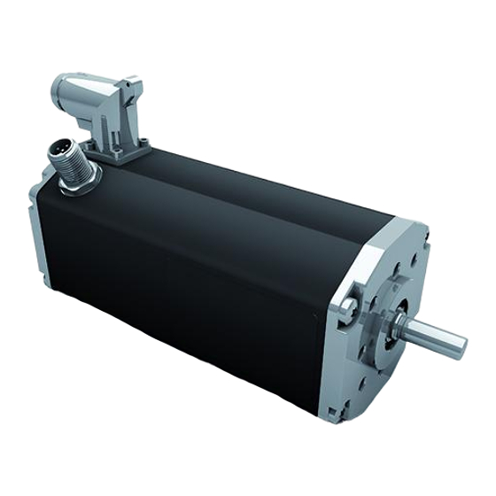
BG65S MI
Instruction Manual
Motor with freely programmable
motion controller integrated
Betriebsanleitung
Motor mit integriertem frei
programmierbaren Motioncontroller
Dunkermotoren GmbH
Allmendstraße 11 · D-79848 Bonndorf/Schwarzwald
www.dunkermotoren.com · info@dunkermotoren.de
Phone +49 (0) 7703 930-0 · Fax +49 (0) 7703 930-210/212
Motor
Part No.
65Sx25
88566.05XXX
65Sx50
88566.06XXX
Advertisement
Table of Contents

Related Manuals for Ametek Dunkermotoren BG65Sx25 MI


Summary of Contents for Ametek Dunkermotoren BG65Sx25 MI
- Page 1 BG65S MI Motor Part No. 65Sx25 88566.05XXX 65Sx50 88566.06XXX Instruction Manual Motor with freely programmable motion controller integrated Betriebsanleitung Motor mit integriertem frei programmierbaren Motioncontroller Dunkermotoren GmbH Allmendstraße 11 · D-79848 Bonndorf/Schwarzwald www.dunkermotoren.com · info@dunkermotoren.de Phone +49 (0) 7703 930-0 · Fax +49 (0) 7703 930-210/212...
-
Page 2: Table Of Contents
1 Content 1 Inhalt 2 About this document 2 Über dieses Dokument 3 General description 3 Allgemeine Beschreibung 3.1 Motor series BG65S MI 3.1 Motorbaureihe BG65S MI 3.2 Explanations of terms used 3.2 Begriffserklärungen 3.3 Proper use 3.3 Bestimmungsgemäße Verwendung 3.4 Standards and guidelines 3.4 Zertifikate/ Konformitäten 4 Safety instructions... - Page 3 8.2.3 Power- and logic supply 8.2.3 Leistungs- und Logikversorgung 8.2.4 Pin Assignment 8.2.4 Steckerbelegung 8.2.5 Mating connector with cable 8.2.5 Gegenstecker mit Anschlussleitung 8.2.6 Connection via 15-pin connector 8.2.6 Anschluss über 15-poligen Stecker for motor für Motor 8.2.7 Connection CAN field bus 8.2.7 Anschluss CAN-Feldbusanschluss 8.2.8 Mating connector with cable 8.2.8 Gegenstecker mit Anschlussleitung...
- Page 4 www.dunkermotoren.de Version 05.2017...
-
Page 5: About This Document
2 About this document 2 Über dieses Dokument Die vorliegende Betriebsanleitung stellt Ihnen die These operating instructions introduce you to the CAN-Antriebe vor und informiert Sie über alle Schritte CAN drive and inform you about all necessary steps for installation and carrying out initial functional tests. zur Installation der Antriebe und zur Durchführung Further information about field bus operation of the erste Funktionstests. -
Page 6: General Description
3 Allgemeine Beschreibung 3 General description 3.1 Motorbaureihe BG65S MI 3.1 Motor series BG65S MI • Bürstenloser DC - Antrieb mit einem integrierten • Brushless DC drive with an integrated freely pro- frei programmierbarem Motioncontroller und grammable motion controller and CANbus inter- CANBus Schnittstelle (CANopen Drives Profil face (CANopen Drive Profile DSP 402). -
Page 7: Explanations Of Terms Used
3.2 Explanations of terms used 3.2 Begriffserklärungen Term Explanation Begriff Erklärung Übertragungs-/ Kommuni- Speed of transmission or Baud rate Baud rate kationsgeschwindigkeit communication Kommunikationsnetzwerk A communication network bei dem alle Knoten über in which all nodes can be passive Links erreicht reached via passive links, werden können und and communication is pos-... -
Page 8: Proper Use
3.3 Proper use 3.3 Bestimmungsgemäße Verwendung - The BG65S MI motor is a supplied part and may be - Der Motor BG65S MI ist ein Zulieferteil und darf in installed into (industrial) machinery and equipment in der beschriebenen Konfiguration in Maschinen the described configuration. -
Page 9: Safety Instructions
4 Safety instructions Grundlegende Sicherheitshinweise Before commissioning, it is Vor der Inbetriebnahme sind unbe- essential that the safety instructions dingt die Sicherheitshinweise zu lesen in the relevant section are read and und zu beachten! Eine Nichtbeach- understood, and then observed! tung kann zu Gefahren bei Personen Non-observance can result in danger oder Beschädigungen an der... -
Page 10: Technical Data, Accessories
5 Technical data, accessories 5 Technische Daten, Zubehör 5.1 Electrical data 5.1 Elektrische Daten Non-destructive Zerstörungsfreier Spannungs- 0 ... 58 VDC 0 ... 58 VDC voltage range power supply bereich Leistungsversorgung Operating voltage range Betriebsspannungsbereich 10 ... 50 VDC 10 ... 50 VDC power supply Leistungsversorgung Non-destructive... -
Page 11: Load Diagram Output Shaft
5.2.1 Load diagram output shaft 5.2.1 Wellenbelastungsdiagramm The permissible shaft load Die zulässigen Wellenbelastungen (axial / radial) depends on the (axial/radial) sind abhängig von der speed. Please consider the following Drehzahl. Beachten Sie hierzu das chart. nachfolgende Diagramm. NOTICE HINWEIS The maximum bearing loads should Bei Gehäusetemperaturen >... -
Page 12: Motor Specification
5.4 Motor specification 5.4 Motorspezifikationen Exceeding of the maximum permitted Überschreiten der maximal zulässigen continuous current! Dauerströme! Die Folge: Consequence: Kann zur Zerstörung des Antriebs The drive may be CAUTION VORSICHT führen. destroyed. ► Mind the maximum permitted ► Die maximal zulässigen Dauerströme beachten! continuous current! BG65Sx25 MI... - Page 13 BG65Sx50 MI BG65Sx50 MI Nominal voltage 24 V Nennspannung 24 V Nominal power 233 W Nennleistung 233 W Nominal torque 49,5 Ncm Nenndrehmoment 49,5 Ncm Recommended 100 min empfohlener 100 min speed control range Nominal speed Drehzahlregelbereich Nenndrehzahl Nominal speed 3725 rpm Nenndrehzahl 3725 U/min...
-
Page 14: Optional Attachments
5.5 Optional attachments 5.5 Optionale Anbauten Worm gear Schneckengetriebe The worm gear is extremely quiet. In many applica- Die Schneckengetriebe zeichnen sich durch hohe tions, the gear shaft shifted by 90° compared to the Laufruhe aus. Bei vielen Anwendungen ist die um 90° motor shaft is ideal with regard to structural aspects. -
Page 15: Types Of Operation
6. Betriebsarten 6. Types of operation Unter anderem sind folgende Betriebsarten möglich: The following types of operation are possible: - Current mode - Current/torque mode - Velocity mode - Velocity mode - Position mode - Position mode - SVEL mode - SVEL mode 6.1 Betrieb mit Inkrementalgeber 6.1 Operation with incremental encoder... -
Page 16: Can-Open Operation With Stored Running Profile
6.3 CAN-open operation with stored 6.3 CAN-open Betrieb mit running profile abgespeichertem Fahrprofil For this type of operation, a pre-defined speed profile Für diese Betriebsart kann ein vordefiniertes Dreh- can be stored in a memory in the motor, whereby run zahlprofil im Motor abgespeichert werden, wobei die commands, which the motion controller has sent to Ausführung über Fahrbefehle erfolgt, die dem Motion-... -
Page 17: Protective Functions
7. Schutzfunktionen 7. Protective functions Der Motor besitzt verschiedene Schutzfunktionen, um The motor has several protection functions to avoid Schäden durch Überbelastung zu vermeiden. Jede damages by overload. dieser Schutzfunktionen wird nachfolgend im Detail Each protection function is described below in detail. beschrieben. - Page 18 7.5 Überspannungsabschaltung 7.5 Over voltage cut-off Leistungsversorgung power stage supply Wenn die Versorgungsspannung die 60 V überschrei- If the power stage supply exceeds 60V the power tet, schaltet die Leistungsstufe ab. Der Fehler kann stage is disabled. The error can be confirmed after the bestätigt werden, nachdem die Versorgungsspannung power stage supply voltage has fallen below 60V.
-
Page 19: Ballastschaltung
7.7 Ballast circuit 7.7 Ballastschaltung The drive provides a 4Q controller. During braking Der Antrieb besitzt einen 4Q Regler. Somit kann beim operations, energy can be fed back and the Bremsen Energie zurückgeführt werden, wodurch die supply voltage increases. To prevent damage Versorgungsspannung ansteigt. -
Page 20: Installation
8 Installation 8 Installation Vor der Inbetriebnahme sind unbe- Before commissioning, it is dingt die Sicherheitshinweise zu essential that the safety instructions lesen und zu beachten! Eine in the relevant section are read and Nichtbeachtung kann zu Gefahren understood, and then observed! WARNUNG WARNING bei Personen oder Beschädigungen... -
Page 21: Anbindung Motorstecker
Connector faces Stecker in Richtung AS to front side Stecker in Richtung NS Connector faces to rear side 8.1.2 Motor connector connection 8.1.2 Anbindung Motorstecker Während dem Verbinden des Kabels mit dem Motor, During connecting of the cable with the motor note achten Sie auf das Symbol H (Siehe Zeichnung). -
Page 22: Winkellage Motorstecker
8.1.3 Winkellage Motorstecker 8.1.3 Angle adjustment motor connector Description Pos. Bezeichnung M3 - grub screw (allen key 1,5 mm) M3 - Gewindestift (Inbusschlüssel 1,5 mm) Durch lösen des M3-Gewindestiftes mit einem Adjust the angle of the motor connector in the 1,5 mm Inbus-Schlüssel kann das Steckergehäuse following way. -
Page 23: Erdung
Erforderliche Maßnahmen: Required measures: Zur Einhaltung der Normen sind folgende Maßnah- To achieve compliance with the standards, the follow- men erforderlich: ing measures are necessary: • Zur Einhaltung der DIN EN 55014-1 (Störspan- • For compliance with DIN EN 55014-1 (Interference nung auf Leitungen für DC-Anschlüsse) sowie zur voltage on cables for DC connectors) as well as Einhaltung der DIN EN 61000-4-6 (hochfrequente... -
Page 24: Power- And Logic Supply
8.2.3 Power- and logic supply 8.2.3 Leistungs- und Logikversorgung Plug: Stecker: Round plug M16, 15-pin Rundstecker M16, 15-polig 8.2.4 Pin Assignment 8.2.4 Steckerbelegung 1 2 3 4 5 6 7 8 10 11 12 Ballast-Connector/Pin B Ballast-Anschluss Pin B 24/ 40 V DC Power/ Leistung: GND: Logic/... -
Page 25: Mating Connector With Cable
8.2.5 Mating connector with cable 8.2.5 Gegenstecker mit Anschlussleitung Connecting cable M16 (Article code 27573 41020) Anschlusskabel M16 (Sachnummer 27573 41020) 8.2.6 Connection via 15-pin connector for motor 8.2.6 Anschluss über 15-poligen Stecker für Motor Lead colour in Ste- Litzenfarbe der An- Plug Connection connection cable with... -
Page 26: Connection Can Field Bus
8.2.7 Connection CAN field bus connection 8.2.7 Anschluss CAN-Feldbusanschluss CAN-high CAN-low 8.2.8 Mating connector with cable 8.2.8 Gegenstecker mit Anschlussleitung Connecting cable (Article code 16597 57033) Anschlusskabel M12 (Sachnummer 16597 57033) www.dunkermotoren.de Version 05.2017... -
Page 27: Electromagnetic Compability
8.2.9 Electromagnetic Compability 8.2.9 Elektromagnetische Verträglichkeit Beim Betrieb können elektromagne- During operation, electromagnetic radia tische Störstrahlungen entstehen. tion may be generated. The signals of Die Signale von Steuerleitungen und control cables and equipment are influ Anlageteilen werden beeinflusst, enced, which may damage the equip wodurch die Anlage beschädigt werden ment. -
Page 28: Earthing
8.2.10 Earthing 8.2.10 Erdung Vermeiden Sie bei allen Erdungskonzepten Avoid loops in all earthing concepts. The die Bildung von Schleifen. shields of all cables should not have any Die Schirmung von Leitungen sollte keine interruptions. Unterbrechung aufweisen. If Dunkermotoren cables are used, the Bei Leitungen länger als 10m sollte die NOTICE HINWEIS... -
Page 29: Schematic Circuit Power Supply
8.2.11 Schematic circuit power supply 8.2.11 Prinzipschaltbild Spannungsversorgung BG65S MI BG65S MI Peak current by switching-on of a Stromspitzen beim Einschalten variety of series-connected mehrerer hintereinander geschal- motors! teter Motoren! Consequence: Die Folge: CAUTION VORSICHT Destroying of the integrated electronics Die integrierte Elektronik kann zerstört possible. -
Page 30: Digital Inputs
8.3 Digital inputs 8.3 Digitaleingänge 8.3.1 Schematic circuit of the digital inputs 8.3.1 Prinzipschaltung der Digitaleingänge Logic supply Logikversorgung to µC zum µC Eingang Input 22nF 22nF 1,2k 1,2k NPN - Input NPN - Eingang Optional for ground switching inputs optional für massegeschaltete Eingänge 8.4 Analog inputs 8.4 Analoge Eingänge... -
Page 31: Commissioning
9 Commissioning 9 Inbetriebnahme All drives of the series BG 45 MI are applied for custo- Da die Antriebe der Baureihe BG 45 MI für Kunden- mer projects, this requires a special commissioning projekte von Dunkermotoren appliziert werden, muss manual depending on the customzid programming of für die Inbetriebnahme in Abhänigkeit der kundenspe- the drives. -
Page 32: Service & Support
10.2 Service & Support 10.2 Service & Support Should you have any questions or problems, please Bei Fragen und Problemen stehen Ihnen folgende An- contact: sprechpartner zur Verfügung: - Your local Dunkermotoren sales outlet - Ihre zuständige Vertretung - Your local Dunkermotoren - Ihr zuständiger Dunkermotoren key account manager Key Account Manager...