
Related Manuals for Ametek dunkermotoren BG 75 SI Series


Summary of Contents for Ametek dunkermotoren BG 75 SI Series
- Page 1 Instruction Manual / Betriebsanleitung BLDC-motor with integrated speed controller EC-Motor mit integriertem Drehzahlregler BG 75 SI Edition / Ausgabe (05/2017)
-
Page 2: Table Of Contents
Page Seite 1 Contents 1 Inhalt 2 About this document 2 Über dieses Dokument 3 General description 3 Allgemeine Beschreibung 3.1 Motor series BG 75 SI 3.1 Motorbaureihe BG 75 SI 3.2 Explanations of terms used 3.2 Begriffserklärungen 3.3 Proper use 3.3 Bestimmungsgemäße Verwendung 3.4 Standards and guidelines 3.4 Normen und Richtlinien... - Page 3 9.3 Function of the digital inputs 9.3 Funktion der Digitaleingänge IN2 and IN3 IN2 und IN3 9.4 Teaching of fixed speeds 9.4 Teachen von festen Geschwindigkeiten 26 9.5 Teaching of ramps 9.5 Teachen von Rampen 9.6 Function of the pulse output OUT1 9.6 Funktion des Pulsausgangs OUT1 9.7 Protection function and fault output 9.7 Schutzfunktionen und Meldeausgang...
-
Page 4: About This Document
2 About this document 2 Über dieses Dokument These operating instructions introduce you to the SI Die vorliegende Betriebsanleitung stellt Ihnen die SI- drives and provide you with information on all the Antriebe vor und informiert Sie über alle Schritte zur stages required for the installation of the drives and Installation der Antriebe und zur Durchführung von the performance of functional tests. -
Page 5: General Description
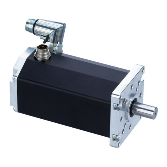
3 General description 3 Allgemeine Beschreibung 3.1 Motor series BG 75 SI 3.1 Motorbaureihe BG 75 SI Bei der Motorbaureihe BG 75 SI handelt es sich um The motor type BG 75 SI represents EC-motors EC-Motoren (bürstenlose DC-Motoren) mit einer inte- (brushless DC motor) with an integrated speed control grierten Drehzahlregelelektronik für den electronic for 4-quadrant operation. -
Page 6: Explanations Of Terms Used
3.2 Explanations of terms used 3.2 Begriffserklärungen Component for the transfor- Bauteil zur Umwandlung von Brückengleichrich- Bridge rectifier mation from AC voltage to DC Wechselspannung in Gleich- voltage spannung Smoothing capaci- Component to smooth the Glättungskonden- Bauteil Glättung fluctuation voltage sator Spannungsschankungen Sensor zur Positionsbestim-... -
Page 7: Standards And Guidelines
3.4 Standards and guidelines 3.4 Normen und Richtlinien EU guidelines: the EU guidelines formulate the mi- EG-Richtlinien: Die EG-Richtlinien formulieren die nimum requirements made on a product and must be Mindestanforderungen an ein Produkt und müssen observed by all manufacturers and dealers marketing von allen Herstellern und Händlern beachtet werden, the product in the member states of the European die das Produkt in den Mitgliedstaaten der Europä-... -
Page 8: Safety Instructions
4 Safety instructions 4 Sicherheitshinweise Vor der Inbetriebnahme sind unbe- Before commissioning, it is dingt die Sicherheitshinweise zu lesen essential that the safety instructions und zu beachten! Eine Nichtbeach- in the relevant section are read and tung kann zu Gefahren bei Personen understood, and then observed! WARNING WARNUNG... -
Page 9: Technical Data, Accessories
5 Technical data, accessories 5 Technische Daten, Zubehör 5.1 Electrical data 5.1 Elektrische Daten Speed range Regelbarer Drehzahl- 0 ... 4092 U/min 0 ... 4092 U/min adjustable bereich Minimum motor Minimal zulässige 7 V DC 7 V DC voltage Motorspannung Maximal zulässige Maximum motor voltage 50 V DC... -
Page 10: Mechanical Data
5.2 Mechanical data 5.2 Mechanische Daten Temperature range -20 °C ... +100 °C Temperaturbereich -20°C…+100°C motor housing temperature Motor Gehäusetemperatur Recommended envi- Empfohlener Umge- 0°C…50°C ronmental temperature 0 °C ... 50 °C bungstemperaturbereich *) range *) Relative Relative humidity Max. 90% Max. -
Page 11: Motor Bg 75X25 Si
5.4 Motor BG 75x25 SI 5.4 Motor BG 75x25 SI Nominal voltage Nennspannung 250 W 284 W 250 W 284 W Nominal power Nennleistung 3900 rpm 3820 rpm 3900 rpm 3820 rpm Rated speed Nenndrehzahl 61 Ncm 71 Ncm 61 Ncm 71 Ncm Nominal torque *) Nenndrehmoment *) -
Page 12: Accessories
5.7 Accessories 5.7 Optionale Anbauten Worm gear (WG): Schneckengetriebe (SG): The worm gear is extremely quiet. In many applica- Die Schneckengetriebe zeichnen sich durch hohe tions, the gear shaft shifted by 90° compared to the Laufruhe aus. Bei vielen Anwendungen ist die um motor shaft is ideal with regard to structural aspects. -
Page 13: Protective Functions
6 Protective functions 6 Schutzfunktionen The objective of protective functions is to protect the Schutzfunktionen dienen dem Schutz des Motors vor motor against damages by use outside of the permitted Zerstörung außerhalb des zulässigen Betriebsbe- operating range. reiches. 6.1 Ballast circuit 6.1 Ballastschaltung During braking operations, kinetic energy is stored as Bei Bremsvorgängen wird die kinetische Energie als... -
Page 14: Installation / Terminal Assignment
7 Installation / terminal assignment 7 Installation und Anschlussbelegung Vor der Inbetriebnahme sind unbe- Before commissioning, it is dingt die Sicherheitshinweise zu lesen essential that the safety instructions und zu beachten! Eine Nichtbeach- in the relevant section are read and tung kann zu Gefahren bei Personen understood, and then observed! WARNING... -
Page 15: Ground Wire
system • Verdeckte Verlegung der geschirmten Leitungen in • Hidden shielded cable routing in metal ducts metallischen Kabelkanälen, • Using additional suppression components (ferrite • Verwendung zusätzlicher Entstörbauteile (Ferrite or filter modules). oder Filtermodule). • Additional storage capacitors • Zusätzliche Speicherkondensatoren The electromagnetic compatibility of the machine must Vor dem Betrieb muss die elektromagnetische Verträg- be tested and ensured before it is put into operation. -
Page 16: Motor Power Supply
7.5 Motor power supply 7.5 Leistungsversorgung Motor Connector: Stecker: Round connector, Intercontec Rundstecker, Fa. Intercontec The 4pin plug for motor power supply. Der 4-polige Stecker dient zur Leistungsversorgung des Motors. Lead colour Litzenfarbe der Con- in connection Ste- Anschlusslei- nec- cable with cker- Anschluss... -
Page 17: Signal Interface Supply
Mating connector with cable (please order in addition) Gegenstecker mit Anschlußleitung (bitte mitbestellen): For the BG 75 SI motors with 4-pin connector, pre- Für die Motoren BG 75 SI mit 4-poligem Anschlußste- assembled connection cables are available in a range cker stehen passende, vorkonfektionierte Anschlußlei- of lengths from stock. - Page 18 Connec- Connec- Function Strand Stecker- Funktion Litzen- tor-Pin tion colour of the schluss farbe der connecting Anschluss- cable with leitung mit 12-pole 12 pol. angular con- Winkelste- nector (*) cker (*) left yellow Links gelb right blue Rechts blau teach-input brown Teach-Eingang braun...
-
Page 19: Schematic Circuit Of The Digital Outputs
7.7 Schematic circuit of the digital inputs 7.7 Prinzipschaltung der Digitaleingänge 7.8 Schematic circuit of the digital outputs 7.8 Prinzipschaltung der Digitalausgänge Output Ausgang Chargeable Mit max. with max. 250 mA 250 mA. belastbar. Mating connector with cable (please order in addition) Gegenstecker mit Anschlußleitung (bitte mitbestellen): For the BG 75 CI motors with 12-pin connector, pre-as- Für die Motoren BG 75 CI mit 12-poligem Anschlußstecker... -
Page 20: Maximum Cable Length And Power Supply
Connector with cable, 12-pin Anschlussleitung mit Winkeldose, 12-polig 7.9 Maximum cable length and 7.9 Maximale Kabellängen und power supply Spannungsversorgung If the supply of power and logic Erfolgt die Versorgung von electronic is procceded by a Leistungs- und Logikteil durch eine common 24V DC power source, a safe gemeinsame 24V DC Spannungs- operation is not always... -
Page 21: Connection Schematic
8 Connection schematic 8 Anschlussschema Vor der Inbetriebnahme sind unbe- Before commissioning, it is dingt die Sicherheitshinweise zu lesen essential that the safety instructions und zu beachten! Eine Nichtbeach- in the relevant section are read and tung kann zu Gefahren bei Personen understood, and then observed! WARNING WARNUNG... -
Page 22: Schematic Circuit For Power Supply Controller/ Motor Bg75 Si
8.1 Schematic circuit for power 8.1 Prinzipschaltbild Spannungs- supply controller/ motor versorgung Regler/ Motor BG75 SI BG75 SI Peak current by switching-on of a Stromspitzen beim Einschalten variety of series-connected mehrerer hintereinander geschal- motors! teter Motoren! Consequence: Die Folge: CAUTION VORSICHT Destroying of the integrated electronics Die integrierte Elektronik kann zerstört... -
Page 23: Connection Motor Power Supply
8.2 Connection motor power 8.2 Anschluss Leistungsversorgung supply Motor + (power) 24 V DC P GND (0V) Functional Earth, Protective Earth on request/ Funktionserde, Schutzerde auf Anfrage Ballast 8.3 Connection signal interface supply 8.3 Anschluss Schnittstellenversorgung Versorgung / Supply: Signale / Signals(E/A): Uc (+24 V) Logik / Logic GND (0V) Logik / Logic n.c. -
Page 24: Operation Hints
9 Operation hints 9 Betriebshinweise 9.1 Operation 9.1 Inbetriebnahme Vor der Inbetriebnahme sind unbe- Before commissioning, it is dingt die Sicherheitshinweise zu lesen essential that the safety instructions und zu beachten! Eine Nichtbeach- in the relevant section are read and tung kann zu Gefahren bei Personen understood, and then observed! WARNING... -
Page 25: Operation
9.2 Function of the digital inputs 9.2 Funktion der Digitaleingänge IN0 and IN1 IN0 und IN1 With the help of the two digital inputs IN0 and IN1, Mit Hilfe der beiden digitalen Eingänge IN0 und IN1 altogether 4 operating conditions can be triggered, lassen sich insgesamt 4 Betriebszustände ansteuern, because of the fact that to each of the both inputs the da jedem der beiden Eingänge die logischen Zustän-... -
Page 26: Teaching Of Fixed Speeds
Die folgenden Betriebszustände können angesteuert The following operating conditions can be triggered: werden: Funktion Function Drehzahlregelbetrieb Controlled motor speed mode nicht belegt not engaged Festdrehzahl Fix adjusted, controlled motor speed spd1 = 200 rpm spd1 = 200 rpm Festdrehzahl Fix adjusted, controlled motor speed spd2 = 2500 rpm spd2 = 2500 rpm 9.4 Teachen von festen Geschwindig... -
Page 27: Teaching Of Ramps
9.5 Teaching of ramps 9.5 Teachen von Rampen In case the motor provides the option (inputs IN2, IN3 Falls der Motor die Option bietet (Eingänge IN2, IN3 lead through), the acceleration and braking ramp can herausgeführt), können die Beschleunigungs- und be adjusted by “teaching”. - Page 28 (Volt) z = 1024 * U /10 T (ms) per (Volt) z = 1024 * U /10 T (ms) pro (number) 1000 rpm (Zahl) 1000 rpm 20000 20000 16004 16004 12008 12008 8012 8012 4016 4016 2018 2018 1019 1019 1004 419,6 1004...
-
Page 29: Function Of The Pulse Output Out1
9.6 Function of the pulse output OUT1 9.6 Funktion des Pulsausgangs OUT1 The pulse output OUT1 provides 12 impulses per motor Der Pulsausgang OUT1 liefert 12 Impulse pro Motor- turn, whereas the pulse duration t and the pulse brake umdrehung, wobei die Pulsdauer t und die Pul- is motor speed addicted. -
Page 30: Protection Function And Fault Output Out2
9.7 Protection function and fault output 9.7 Schutzfunktionen und Meldeausgang OUT2 OUT2 The protection function serves for protecting the motor Die Schutzfunktionen dienen dem Schutz des Motors against destruction e.g. at external strain. Confirma- vor Zerstörung z.B. bei extremer Belastung. Quittier- ble protection functions turn off the output stage when bare Schutzfunktionen schalten die Endstufe bei Er- achieving a marginal value. -
Page 31: Function Of The Analogue Input Ai+/Ai
9.8 Function of the analogue input 9.8 Funktion des Analogeinganges AI+/AI- AI+/AI- The input circuit of the analogue input is designed Die Eingangsschaltung des Analogeingangs ist als as differential amplifier with an input resistance of 100 Differenzverstärker mit einem Eingangswiderstand kOhm. -
Page 32: Motors With Additional Brake
9.9 Motoren mit zusätzlicher Bremse 9.9 Motors with additional brake High wear of contact material and Kontaktabbrand und Spannungs- energy intense voltage peaks by using spitzen bei Motoren mit a motor with attached brake! angebauter Bremse! Consequence: Die Folge: CAUTION VORSICHT Destroying of electrical components Zerstörung elektrischer Bauteile... -
Page 33: Maintenance & Service
Rotor stop brake with 6-pole connector plug Ankerstoppbremse mit 6-pol. Anschlussstecker Connection Anschluss +24 V for brake +24 V für Bremse 0 V for brake 0 V für Bremse n.c. n.c. n.c. n.c. n.c. n.c. n.c. n.c. 10 Maintenance & Service 10 Wartung &... -
Page 34: Scope Of Delivery And Accessories
You can download this operating manual in PDF for- Die PDF-Datei dieser Betriebsanleitung und weitere mat and obtain more information by visiting us on the Informationenen stehen für Sie im Internet unter Internet at www.dunkermotoren.de/downloads. www.dunkermotoren.de/downloads bereit. Dunkermotoren GmbH Dunkermotoren GmbH Allmendstrasse 11 Allmendstrasse 11 D-79848 Bonndorf...
Need help?
Do you have a question about the dunkermotoren BG 75 SI Series and is the answer not in the manual?
Questions and answers