Sign In
Upload
Manuals
Brands
Ametek Manuals
Engine
dunkermotoren BG 66x75 dMove
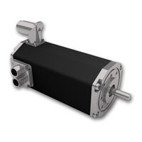
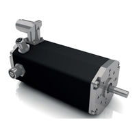
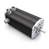
Ametek dunkermotoren BG 66x75 dMove Manuals
Manuals and User Guides for Ametek dunkermotoren BG 66x75 dMove. We have
3
Ametek dunkermotoren BG 66x75 dMove manuals available for free PDF download: Translation Of The Original Function And Connection Manual
Ametek dunkermotoren BG 66x75 dMove Translation Of The Original Function And Connection Manual (59 pages)
Brand:
Ametek
| Category:
Engine
| Size: 4.92 MB
Table of Contents
Table of Contents
2
About this Documentation
5
Zu dieser Dokumentation
5
Liability and Warranty
6
Target Group
6
Safety Notes
6
Haftung und Gewährleistung
6
Zielgruppe
6
Sicherheitshinweise
6
Further Icons
7
Hazard Signs
7
Weitere Piktogramme
7
Gefahrenzeichen
7
EC/EU Declaration of Conformity
8
Directives Low-Voltage Directive (LVD) 2014/35/EU
8
EG/EU-Konformitätserklärung
8
Richtlinie Niederspannungsrichtlinie (NSR) 2014/35/EU
8
Safety Notes
9
Intended Use
9
Expected Misuse
9
Sicherheitshinweise
9
Bestimmungsgemäße Verwendung
9
Vorhersehbarer Fehlgebrauch
9
Basic Safety Notes
10
Safety Notes for Staff
10
Grundlegende Sicherheitshinweise
10
Sicherheitshinweise für Personal
10
Safety Notes Concerning Operating Phases
11
Transport
11
Installation
11
Cleaning
11
Maintenance/Repair
11
Environmentally Compatible Disposal
11
Sicherheitshinweise zu Betriebsphasen
11
Reinigung
11
Wartung/Reparatur
11
Umweltgerecht Entsorgen
11
Notes Concerning Special Hazard Types
12
Electrical Energy/Electromagnetic Safety
12
Mechanical Safety
12
Hinweise auf Besondere Gefahrenarten
12
Elektrische Energie/Elektromagnetische Sicherheit
12
Mechanische Sicherheit
12
Transport and Storage
13
Transport und Lagerung
13
Product Description
14
Design
14
Produktbeschreibung
14
Aufbau
14
Starter Kit
15
Software Drive Assistant 5
15
Optional Attachments
15
Optionale Anbauten
15
Functions
16
Funktionen
16
Type of Control Canopen Dpro CO
17
Ansteuerungsvariante Canopen Dpro CO
17
Type of Control PROFINET Dpro PN
19
Ansteuerungsvariante PROFINET Dpro PN
19
Type of Control Ethercat Dpro EC
20
Ansteuerungsvariante Ethercat Dpro EC
20
Type of Control Ethernet/Ip Dpro EI
21
Ansteuerungsvariante Ethernet/Ip Dpro EI
21
Type of Control Dpro IO
22
Ansteuerungsvariante Dpro IO
22
Protective Functions
23
4.11.1 Overtemperature Protection
23
4.11.2 Undervoltage Switch-Off of the Logic Supply
23
Undervoltage Switch-Off of the Power-Supply
23
Schutzfunktionen
23
4.11.1 Übertemperaturschutz
23
4.11.2 Unterspannungsabschaltung Logikversorgung
23
Unterspannungsabschaltung Leistungs- Versorgung
23
Current Limitation (I T)
24
Strombegrenzung (I T)
24
4.11.5 Ballast Circuit
26
4.11.5 Ballastschaltung
26
Voltage Controlled Braking
28
4.11.7 Thresholds Protection Functions
28
Spannungsgeregeltes Bremsen
28
4.11.7 Grenzwerte Schutzfunktionen
28
Technical Data
29
Product Specification
29
Technische Daten
29
Produktspezifikation
29
Electrical Data
31
Environmental Conditions
31
Elektrische Daten
31
Umgebungsbedingungen
31
Dimensional Drawing
32
Maßzeichnung
32
Shaft Load Chart
33
Wellenbelastungsdiagramm
33
Motor Label
34
Typenschild
34
Installation
35
Mechanical Assembly
36
Mechanische Montage
36
Electrical Assembly
37
Elektrische Montage
37
EMC Compliant Installation
38
EMV-Konforme Installation
38
Protective Earth Conductor
39
Protective Earthing
39
Schutzleiter
39
Schutzerdung
39
Power and Logic Supply
40
Inputs and Outputs
40
Power and Logic Supply, Inputs and Outputs
40
Leistungs- und Logikversorgung, Ein- und Ausgänge
40
Mating Connector with Connection Cable
43
Connecting Motor to Connection Cable
43
Gegenstecker mit Anschlussleitung
43
Motor mit Anschlusskabel Verbinden
43
Power and Logic Supply, Inputs and Outputs (Legacy)
44
Leistungs- und Logikversorgung, Ein- und Ausgänge (Legacy)
44
Canopen Fieldbus Connection (Only for IO/CO Versions)
47
Canopen-Feldbusanschluss (nur bei IO/CO Versionen)
47
Canopen Mating Connector with Connection Cable (Only for IO/CO Versions)
48
Canopen-Gegenstecker mit Anschlussleitung (nur bei IO/CO Versionen)
48
External Encoder Interface (Optionally)
49
Externe Encoder Schnittstelle (Optional)
49
Industrial Ethernet Interface (for PN/EC/EI Motors)
50
Industrial Ethernet Schnittstelle (für PN/EC/EI Motoren)
50
Industrial Ethernet Mating Connector with Connection Cable (Only for PN, EC and EI Version)
51
Industrial Ethernet Gegenstecker mit Anschlussleitung (nur für PN, EC und EI Version)
51
Power Supply Connection
52
Anschluss Spannungsversorgung
52
Circuit Diagram for BG 66 Dpro Motors with and Without Safe Torque off (STO)
53
Schaltplan für BG 66 Dpro Motoren mit und ohne Sicherer Abschaltung (STO)
53
Starter Kit for Dmove and Dpro IO/CO
54
Starter Kit für Dmove und Dpro IO/CO
54
Principle Circuit Diagram of Digital Inputs
55
Principle Circuit Diagram of Analogue Inputs
55
Principle Circuit Diagram of Digital Outputs
55
Prinzipschaltbild Digitaleingänge
55
Prinzipschaltbild Analogeingänge
55
Prinzipschaltbild Digitalausgänge
55
Maintenance
56
Decommissioning and Disposal
56
Wartung
56
Außerbetriebnahme und Entsorgung
56
Service and Support
57
Service und Support
57
Imprint
58
Impressum
58
Advertisement
Ametek dunkermotoren BG 66x75 dMove Translation Of The Original Function And Connection Manual (54 pages)
Brand:
Ametek
| Category:
Engine
| Size: 5.52 MB
Table of Contents
Table of Contents
2
About this Documentation
5
Zu dieser Dokumentation
5
Liability and Warranty
6
Target Group
6
Safety Notes
6
Haftung und Gewährleistung
6
Zielgruppe
6
Sicherheitshinweise
6
Further Icons
7
Hazard Signs
7
Weitere Piktogramme
7
Gefahrenzeichen
7
EC/EU Declaration of Conformity
8
Directives Low-Voltage Directive (LVD) 2014/35/EU
8
EG/EU-Konformitätserklärung
8
Richtlinie Niederspannungsrichtlinie (NSR) 2014/35/EU
8
Safety Notes
9
Intended Use
9
Expected Misuse
9
Sicherheitshinweise
9
Bestimmungsgemäße Verwendung
9
Vorhersehbarer Fehlgebrauch
9
Basic Safety Notes
10
Safety Notes for Staff
10
Grundlegende Sicherheitshinweise
10
Sicherheitshinweise für Personal
10
Safety Notes Concerning Operating Phases
11
Transport
11
Installation
11
Cleaning
11
Maintenance/Repair
11
Environmentally Compatible Disposal
11
Sicherheitshinweise zu Betriebsphasen
11
Reinigung
11
Wartung/Reparatur
11
Umweltgerecht Entsorgen
11
Notes Concerning Special Hazard Types
12
Electrical Energy/Electromagnetic Safety
12
Mechanical Safety
12
Hinweise auf Besondere Gefahrenarten
12
Elektrische Energie/Elektromagnetische Sicherheit
12
Mechanische Sicherheit
12
Transport and Storage
13
Transport und Lagerung
13
Product Description
14
Design
14
Produktbeschreibung
14
Aufbau
14
Starter Kit
15
Software Drive Assistant 5
15
Optional Attachments
15
Optionale Anbauten
15
Functions
16
Funktionen
16
Type of Control Canopen Dmove CO
17
Ansteuerungsvariante Canopen Dmove CO
17
Type of Control Dmove IO
19
Ansteuerungsvariante Dmove IO
19
Protective Functions
20
Overtemperature Protection
20
Undervoltage Switch-Off of the Logic Supply
20
Undervoltage Switch-Off of the Power-Supply
20
Schutzfunktionen
20
Übertemperaturschutz
20
Unterspannungsabschaltung Logikversorgung
20
Unterspannungsabschaltung Leistungs- Versorgung
20
Current Limitation (I T)
21
Strombegrenzung (I T)
21
Ballast Circuit (Optional)
24
Ballastschaltung (Optional)
24
Voltage Controlled Braking
25
Thresholds Protection Functions
25
Spannungsgeregeltes Bremsen
25
Grenzwerte Schutzfunktionen
25
Technical Data
26
Product Specification BG 65 Dmove
26
Technische Daten
26
Produktspezifikation BG 65 Dmove
26
Product Specification BG 66 Dmove
27
Produktspezifikation BG 66 Dmove
27
Electrical Data
28
Environmental Conditions
28
Elektrische Daten
28
Umgebungsbedingungen
28
Dimensional Drawing BG 65 Dmove CO (with CAN-Connector)
29
Dimensional Drawing BG 65 Dmove IO (Without CAN-Connector)
29
Maßzeichnung BG 65 Dmove CO (mit CAN-Stecker)
29
Maßzeichnung BG 65 Dmove IO (ohne CAN-Stecker)
29
Dimensional Drawing BG 66 Dmove CO (with CAN-Connector)
30
Dimensional Drawing BG 66 Dmove IO (Without CAN-Connector)
30
Maßzeichnung BG 66 Dmove CO (mit CAN-Stecker)
30
Maßzeichnung BG 66 Dmove IO (ohne CAN-Stecker)
30
Shaft Load Chart
31
Wellenbelastungsdiagramm
31
Motor Label
32
Typenschild
32
Installation
33
Mechanical Assembly
34
Mechanische Montage
34
Electrical Assembly
35
Elektrische Montage
35
EMC Compliant Installation
36
EMV-Konforme Installation
36
Protective Earth Conductor
37
Protective Earthing
37
Schutzleiter
37
Schutzerdung
37
Power and Logic Supply
38
Inputs and Outputs
38
Power and Logic Supply, Inputs and Outputs
38
Leistungs- und Logikversorgung, Ein- und Ausgänge
38
Mating Connector with Connection Cable
41
Connecting Motor to Connection Cable
41
Gegenstecker mit Anschlussleitung
41
Motor mit Anschlusskabel Verbinden
41
Power and Logic Supply, Inputs and Outputs (Legacy)
42
Leistungs- und Logikversorgung, Ein- und Ausgänge (Legacy)
42
Connector with Cable, 15 Pin
44
Anschlussleitung mit Dose, 15-Polig
44
Canopen Fieldbus Connection (Only for CO Versions)
45
Canopen-Feldbusanschluss (nur für CO Versionen)
45
Canopen Mating Connector with Connection Cable (Only for CO Versions)
46
Canopen-Gegenstecker mit Anschlussleitung (nur für CO Versionen)
46
Power Supply Connection
47
Anschluss Spannungsversorgung
47
Circuit Diagram for BG 65/66 Dmove Motors
48
Schaltplan für BG 65/66 Dmove Motors
48
Starter Kit for Dmove and Dpro IO/CO
49
Starter Kit für Dmove und Dpro IO/CO
49
Principle Circuit Diagram of Digital Inputs
50
Principle Circuit Diagram of Analogue Inputs
50
Principle Circuit Diagram of Digital Outputs
50
Prinzipschaltbild Digitaleingänge
50
Prinzipschaltbild Analogeingänge
50
Prinzipschaltbild Digitalausgänge
50
Maintenance
51
Decommissioning and Disposal
51
Wartung
51
Außerbetriebnahme und Entsorgung
51
Service and Support
52
Service und Support
52
Imprint
53
Impressum
53
Ametek dunkermotoren BG 66x75 dMove Translation Of The Original Function And Connection Manual (45 pages)
Brand:
Ametek
| Category:
Engine
| Size: 3.44 MB
Table of Contents
English
2
Table of Contents
2
About this Documentation
5
Zu dieser Dokumentation
5
Target Group
6
Safety Notes
6
Zielgruppe
6
Sicherheitshinweise
6
Further Icons
7
EC Declaration of Conformity
7
Weitere Piktogramme
7
EG-Konformitätserklärung
7
Directives
8
Richtlinien
8
Safety Notes
9
Intended Use
9
Sicherheitshinweise
9
Bestimmungsgemäße Verwendung
9
Basic Safety Notes
10
Safety Notes for Staff
10
Grundlegende Sicherheitshinweise
10
Sicherheitshinweise für Personal
10
Safety Notes Concerning Operating Phases
11
Transport
11
Installation
11
Cleaning
11
Maintenance/Repair
11
Environmentally Compatible Disposal
11
Sicherheitshinweise zu Betriebsphasen
11
Reinigung
11
Wartung/Reparatur
11
Umweltgerecht Entsorgen
11
Electrical Energy/Electromagnetic Safety
12
Mechanical Safety
12
Elektrische Energie/Elektromagnetische Sicherheit
12
Mechanische Sicherheit
12
Transport and Storage
13
Transport und Lagerung
13
Product Description
14
Design
14
Produktbeschreibung
14
Aufbau
14
Motion Starter Kit
15
Software Drive Assistant
15
Optional Attachments
15
Optionale Anbauten
15
Functions
16
Operating Mode Canopen CO
17
Operating Mode IO
19
Protective Functions
20
Overtemperature Protection
20
Undervoltage Switch-Off of the Logic Supply
20
Undervoltage Switch-Off of the Power-Supply
20
Current Limitation (I T)
21
Ballast Circuit (Optional)
21
Voltage Controlled Braking
22
Thresholds Protection Functions
22
Technical Data
23
Motor Specification
23
Electrical Data
24
Environmental Conditions
24
Dimensional Drawing with CAN Plug (Dmove CO)
25
Dimensional Drawing Without CAN Plug (Dmove IO)
25
Shaft Load Chart
26
Motor Label
27
Installation
28
Mechanical Assembly
28
Electrical Assembly
29
Shielding
30
Protective Earth Conductor
30
Earthing
30
EMV-Konforme Installation
31
Power and Logic Supply, Inputs and Outputs
32
Connector with Cable, 15 Pin
34
Canopen Fieldbus Connection (Only for CO Versions)
35
Canopen Mating Connector with Connection Cable (for CO Mode Only)
36
Power Supply Connection
37
Circuit Diagram for BG 66 Dmove Motors
38
Principle Circuit Diagram of Digital Inputs
39
Principle Circuit Diagram of Analogue Inputs
39
Principle Circuit Diagram of Digital Outputs
39
Maintenance
40
Decommissioning and Disposal
40
Service and Support
40
Imprint
41
Appendix
42
German
6
Liability and Warranty
6
Haftung und Gewährleistung
6
Hazard Signs
7
Gefahrenzeichen
7
Expected Misuse
9
Vorhersehbarer Fehlgebrauch
9
Notes Concerning Special Hazard Types
12
Hinweise auf Besondere Gefahrenarten
12
Funktionen
16
Betriebsmodus Canopen CO
17
Betriebsmodus IO
19
Schutzfunktionen
20
Übertemperaturschutz
20
Unterspannungsabschaltung Logikversorgung
20
Unterspannungsabschaltung Leistungs- Versorgung
20
Strombegrenzung (I T)
21
Ballastschaltung (Optional)
21
Spannungsgeregeltes Bremsen
22
Grenzwerte Schutzfunktionen
22
Technische Daten
23
Motorspezifikationen
23
Elektische Daten
24
Umgebungsbedingungen
24
Maßzeichnung mit CAN-Stecker (Dmove CO)
25
Maßzeichnung ohne CAN-Stecker (Dmove IO)
25
Wellenbelastungsdiagramm
26
Typenschild
27
Mechanische Montage
28
Elektrische Montage
29
Schirmung
30
Schutzleiter
30
Erdung
30
Leistung und Logikversorgung, Ein- und Ausgänge
32
Anschlussleitung mit Dose, 15-Polig
34
Canopen-Feldbusanschluss (nur bei CO Versionen)
35
Canopen-Gegenstecker mit Anschlussleitung (nur für CO Modus)
36
Anschluss Spannungsversorgung
37
Schaltplan für BG 66 Dmove Motors
38
Prinzipschaltbild Digitaleingänge
39
Prinzipschaltbild Analogeingänge
39
Prinzipschaltbild Digitalausgänge
39
Wartung
40
Außerbetriebnahme und Entsorgung
40
Service und Support
40
Impressum
41
Anhang
42
Advertisement
Advertisement
Related Products
Ametek dunkermotoren BG 66x25 dMove
Ametek dunkermotoren BG 66x50 dMove
Ametek dunkermotoren BG 66 dPro CO
Ametek dunkermotoren BG 66 dMove Series
Ametek dunkermotoren BG 65
Ametek Dunkermotoren BG65Sx25 MI
Ametek dunkermotoren BG 65x75 dMove
Ametek dunkermotoren BG 65x50 dMove
Ametek dunkermotoren BG 65x25 dMove
Ametek dunkermotoren BG 65 dMove Series
Ametek Categories
Measuring Instruments
Test Equipment
Power Supply
Controller
Laboratory Equipment
More Ametek Manuals
Login
Sign In
OR
Sign in with Facebook
Sign in with Google
Upload manual
Upload from disk
Upload from URL