Ametek dunkermotoren BG 66x25 dMove Translation Of The Original Function And Connection Manual
Hide thumbs
Also See for dunkermotoren BG 66x25 dMove:

Related Manuals for Ametek dunkermotoren BG 66x25 dMove


Summary of Contents for Ametek dunkermotoren BG 66x25 dMove
- Page 1 Original Funktions- und Anschlussbeschreibung/ Translation of the original function and connection guide BG 66 dMove Typ: Part No: BG 66x25 dMove 88566.14XXX BG 66x50 dMove 88566.15XXX BG 66x75 dMove 88566.16XXX...
-
Page 2: Table Of Contents
Content Inhalt 1. About this Documentation ....5 1. Zu dieser Dokumentation...... 5 Liability and Warranty .......... 6 Haftung und Gewährleistung ....... 6 Target Group ............6 Zielgruppe ............6 Safety Notes ............6 Sicherheitshinweise ..........6 Further Icons ............7 Weitere Piktogramme .......... - Page 3 Functions ............16 Funktionen ............16 Operating Mode CANopen CO ......17 Betriebsmodus CANopen CO ......17 Operating Mode IO ........... 19 Betriebsmodus IO ..........19 Protective Functions .......... 20 Schutzfunktionen ..........20 4.8.1 Overtemperature Protection ......20 4.8.1 Übertemperaturschutz ........20 4.8.2 Undervoltage Switch-Off of the Logic Supply ..
- Page 4 6.7.1 Connector with Cable, 15 pin ......34 6.7.1 Anschlussleitung mit Dose, 15-polig ....34 CANopen Fieldbus Connection CANopen-Feldbusanschluss (only for CO versions) ........35 (nur bei CO Versionen) ........35 6.8.1 CANopen Mating Connector with Connection 6.8.1 CANopen-Gegenstecker mit Anschlussleitung Cable (for CO Mode only) ........
-
Page 5: About This Documentation
About this Documentation Zu dieser Dokumentation This documentation is targeted at people who are Diese Dokumentation richtet sich an Personen, die mit charged with transport, assembly and connection of the Transport, Montage und Anschluss des Motors beauftragt motor. sind. Read the instructions and information carefully. Lesen Sie die Anleitungen und Informationen sorgfäl- tig durch. -
Page 6: Liability And Warranty
Haftung und Gewährleistung Liability and Warranty Dunkermotoren GmbH does not accept any liability or Die Dunkermotoren GmbH übernimmt keine Haftungs- warranty claims for injury and property damage due to und Gewährleistungsansprüche der Personen und Sach- one or several of the following causes: schaden, wenn sie auf einen oder mehrere der folgenden Ursachen zurückzuführen sind: »... -
Page 7: Further Icons
Further Icons Weitere Piktogramme This document uses the following icons: In diesem Dokument werden folgende Piktogramme ver- wendet: Symbol/ Meaning/ Symbol Bedeutung Observe operating instructions/ Gebrauchsanweisung beachten Earth before use/ Vor Benutzung erden Recommendations/ Empfehlungen Instruction to act/ Handlungsaufforderung Hazard Signs Gefahrenzeichen The hazard signs inform about potential hazards and Die Gefahrenzeichen weisen auf mögliche Gefahren hin... -
Page 8: Directives
Directives Richtlinien Niederspannungsrichtlinie (NSR) 2014/35/EU Low-Voltage Directive (LVD) 2014/35/EU The low-voltage directive (LVD) 2014/35/EU applies to all Die Niederspannungsrichtlinie (NSR) 2014/35/EU gilt für electrical devices with a nominal voltage between 75 and alle elektrischen Geräte mit einer Nennspannung zwi- 1,500 VDC, or between 50 and 1,000 VAC. The nomi- schen 75 bis 1.500 VDC, bzw. -
Page 9: Safety Notes
Safety Notes Sicherheitshinweise The safety notes are only part of the technical documen- Die Sicherheitshinweise sind nur ein Teil der technischen tation of this motor. They must be read in connection with Dokumentation dieses Motors. Sie sind im Zusammen- the other technical documentation. hang mit den anderen technischen Dokumentationen zu sehen. -
Page 10: Basic Safety Notes
Basic Safety Notes Grundlegende Sicherheitshinweise Only use the motors in an impeccable condition. Verwenden Sie die Motoren nur im einwandfreien Zustand. Observe the technical data and environmental condi- tions indicated in the documentation. Halten Sie die in der Dokumentation angegebenen technischen Daten und Umgebungsbedingungen ein. -
Page 11: Safety Notes Concerning Operating Phases
Safety Notes concerning Operating Phases Sicherheitshinweise zu Betriebsphasen 2.5.1 Transport 2.5.1 Transport Transportieren Sie den Motor nur in der Originalverpa- Transport the motor only in its original packaging. ckung. Ensure that the transported goods are sufficiently secured. Sorgen Sie für ausreichende Sicherung des Transport- guts. -
Page 12: Notes Concerning Special Hazard Types
Notes concerning Special Hazard Types Hinweise auf besondere Gefahrenarten 2.6.1 Electrical Energy/Electromagnetic 2.6.1 Elektrische Energie/elektromagnetische Safety Sicherheit Operation of the motor or the entire equipment will produ- Beim Betrieb des Motors bzw. der gesamten Anlage ce electromagnetic interferences. These may influence the entstehen elektromagnetische Störungen. -
Page 13: Transport And Storage
Transport and Storage Transport und Lagerung Observe the environmental conditions during transport Beachten Sie bei Transport und Lagerung die Umge- and storage. If your storage and transport conditions bungsbedingungen. Falls Sie davon abweichende Lage- deviate from these (see table below), please contact us so rungs- und Transportbedingungen haben (siehe Tabelle that we can review potential impacts on your products. -
Page 14: Product Description
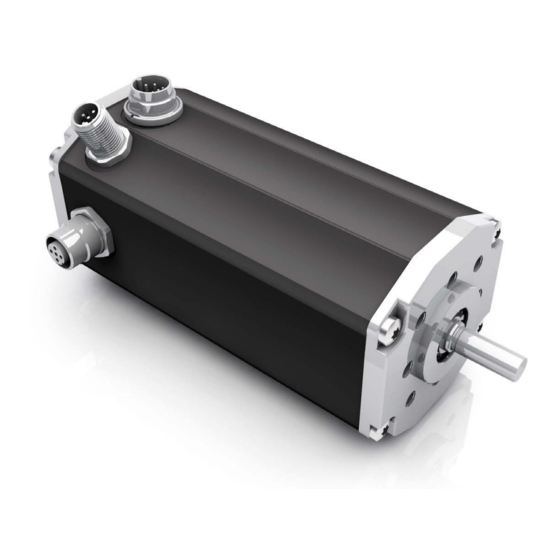
Product Description Produktbeschreibung Design Aufbau » The BG 66 dMove motor series are brushless DC » Bei der Motorbaureihe BG 66 dMove handelt es sich servomotors with integrated motion controllers. The um bürstenlose DC-Servomotoren mit integriertem comfortable PC operating interface makes it easy to Motioncontroller und komfortabler Bedienoberfläche set drive parameters for a number of pre-installed für PC, auf der sich die Antriebe für eine Reihe vor-... -
Page 15: Motion Starter Kit
Motion Starter Kit Motion Starter Kit The Motion Starter Kit is needed in order to integrate a Um einen Antrieb bzw. externen Regler über einen PC in drive unit or external controller into a CANopen network ein CANopen-Netzwerk als Slave zu integrieren, benötigt as a slave via a PC. -
Page 16: Functions
Functions Funktionen The BG 66 dMove is available with CO and IO functionali- Der BG 66 dMove ist mit CO und IO Funktionalität erhält- ty. Information on this is available from Dunkermotoren. lich. Informationen dazu erhalten Sie bei Dunkermotoren. Various functions are available for any selected control: Unabhängig von der ausgewählten Ansteuerung stehen vielfältige Funktionen zur Verfügung: »... -
Page 17: Operating Mode Canopen Co
Operating Mode CANopen CO Betriebsmodus CANopen CO The communication protocol CANopen supports you Das Kommunikationsprotokoll CANopen unterstützt Sie in linking complex devices. In addition to the network bei der Vernetzung komplexer Geräte. Neben dem Netz- management and device monitoring, communication werkmanagement und der Geräteüberwachung wird auch between various nodes is supported as well. - Page 18 CANopen interfaces CANopen – Schnittstellen Profile Position Mode (CiA 402 Mode 1) Profile Position Mode (CiA 402 Mode 1) The „Profile Position Mode“ serves positioning from a start Der "Profile Position Mode" dient der Positionierung von to a target point. Positioning takes place with reference to einem Start- zu einem Zielpunkt.
-
Page 19: Operating Mode Io
Operating Mode IO Betriebsmodus IO In IO mode, the BG 66 dMove can be operated ‚stand- Im IO Modus kann der BG 66 dMove ‚stand-alone‘ be- alone‘. The motor is then controlled via digital or analogue trieben werden. Angesteuert wird der Motor dann über Inputs. -
Page 20: Protective Functions
Protective Functions Schutzfunktionen The motor has various protection functions to avoid da- Der Motor besitzt verschiedene Schutzfunktionen, um mage from overload. Each of these protection functions is Schäden durch Überbelastung zu vermeiden. Jede dieser described in detail below. The output stage switches off Schutzfunktionen wird nachfolgend im Detail beschrieben. -
Page 21: Current Limitation (I T)
4.8.4 Strombegrenzung (I 4.8.4 Current Limitation (I The motor is protected from thermal overload by an I²t- Der Motor ist durch einen I²t-basierten Algorithmus gegen based algorithm. It calculates the heat supply caused by thermische Überlastung geschützt. Er berechnet die the phase current and limits the nominal current if the cal- durch den Phasenstrom verursachte Wärmezufuhr und culated motor temperature exceeds the critical threshold. -
Page 22: Voltage Controlled Braking
The ballast circuit of the drive unit must be used to avoid Um eine Überhöhung der Versorgungsspannung zu ver- an excessive supply voltage. This protection function is hindern, muss die Ballastschaltung des Antriebs genutzt sensible in regular operation as well. For this, an Ohmic werden. -
Page 23: Technical Data
Technical Data Technische Daten Motor Specification Motorspezifikationen Technical data/ BG 66x25 dMove BG 66x50 dMove BG 66x75 dMove Technische Daten vorläufig Nominal voltage/ Nennspannung Nominal current/ Nennstrom Nominal torque/ 0,34 0,38 0,53 0,55 0,75 Nennmoment Nominal speed/ rpm* 3820 3600 3480 3440 3540... -
Page 24: Electrical Data
Electrical Data Elektische Daten BG 66 dMove 24 V 48 V Operating voltage range power supply/ 5 ... 58 5 ... 58 Betriebsspannungsbereich Leistungsversorgung Operating voltage range logic supply/ 9 ... 30 Betriebsspannungsbereich Logikversorgung Max. permissible ripple supply Max. zulässige Restwelligkeitversorgung * Protection, external power supply/ B-type 16 B-type 16... -
Page 25: Dimensional Drawing With Can Plug (Dmove Co)
Dimensional Drawing with CAN plug Maßzeichnung mit CAN-Stecker (dMove CO) (dMove CO) Motor/ Length L/ Motor Länge L BG 66x25 dMove 115±1 BG 66x50 140±1 dMove BG 66x75 dMove 165±1 Dimensional Drawing without CAN plug Maßzeichnung ohne CAN-Stecker (dMove IO) (dMove IO) Motor/ Length L/... -
Page 26: Shaft Load Chart
Shaft load chart Wellenbelastungsdiagramm NOTICE ACHTUNG Motor damage Motorschaden The permissible shaft loads (axial/radial) depend on the Die zulässigen Wellenbelastungen (axial/radial) sind speed. Observe the following chart for this. The motor abhängig von der Drehzahl. Beachten Sie hierzu das may fail early if overloaded. nachfolgende Diagramm. -
Page 27: Motor Label
Motor label Typenschild unkermotoren BG 66 dMove SNR 88595 05000 24 V= n 3724 rpm I 34 A FW 03600/1 PS 05000/1 MP 06000/1 48/16 BG2 CI. F ID 127 Bd 125 Kundenzeile max. 30 Zeichen Sondertext max. 30 Zeichen Description/ Position Bezeichnung... -
Page 28: Installation
Installation Installation The safety notes must be read and ob- Vor der Inbetriebnahme sind unbedingt served before commissioning. Non-ob- die Sicherheitshinweise zu lesen und zu servation may cause danger to people beachten. Eine Nichtbeachtung kann zu or damage to the machine. Gefahren für Personen oder Beschädi- gungen an der Maschine führen. -
Page 29: Electrical Assembly
Electrical Assembly Elektrische Montage WARNING WARNUNG Injury and product damage from electri- Personen- und Produktschaden durch cal voltages elektrische Spannungen The safety notes must be read and Vor der Inbetriebnahme sind unbedingt observed before commissioning. Non-ob- die Sicherheitshinweise zu lesen und zu servation may cause danger to people or beachten. -
Page 30: Shielding
Shielding Schirmung Note that protection from influence by Beachten Sie, dass ohne Erdung des electromagnetic fields is not provided if Schirms ein Schutz gegen Beeinflus- the shield is not earthed. sung durch elektromagnetische Felder nicht gegeben ist. Connect the shield at each cable end to system Schirm an jedem Leitungsende gegen Anlagenerde ground over a large area. -
Page 31: Emv-Konforme Installation
EMV-konforme Installation EMV-konforme Installation WARNING WARNUNG High-frequency interference (radio inter- Hochfrequente Störungen (Funkstörun- ference gen) If the motor/control electronics are not Wird der Motor nicht entsprechend den installed accordingly the instructions in Anweisungen in Betrieb genommen und operation, it can create Interference with verwendet, kann es zu Störungen von radio transmission. -
Page 32: Power And Logic Supply, Inputs And Outputs
Power and Logic Supply, Leistung und Logikversorgung, Inputs and Outputs Ein- und Ausgänge NOTICE ACHTUNG Short circuit Kurzschluss Bent connector pins can destroy the drive unit by short Umgebogene Stecker-Pins können den Antrieb durch circuit. Kurzschluss zerstören. Ensure that the connectors are not damaged during Achten Sie bei der Installation darauf, dass die installation. - Page 33 Connection via 15-pin connector for motor Anschluss über 15-poligen Stecker für Motor Lead colour of the connection cable with 12+3-pin Plug pin/ connector Connection/ Anschluss Stecker Pin Litzenfarbe der Anschlussleitung mit 12+3-poligem Stecker blue/ blau schwarz black/ N. C. brown/ braun yellow/ gelb...
-
Page 34: Connector With Cable, 15 Pin
6.7.1 Connector with Cable, 15 pin 6.7.1 Anschlussleitung mit Dose, 15-polig Matching pre-fabricated connection cables are available Für die Motoren BG 66 dMove mit 12+3-poligem An- for the motors BG 66 dMove with a 12+3-pin connector. schlussstecker stehen passende, vorkonfektionierte An- schlussleitungen zur Verfügung. -
Page 35: Canopen Fieldbus Connection (Only For Co Versions)
CANopen Fieldbus Connection CANopen-Feldbusanschluss (only for CO versions) (nur bei CO Versionen) The CANopen interface and the connectors used corre- Die CANopen Schnittstelle und die verwendeten Steck- spond to the CiA 303-1-standard. This standard contains verbinder entsprechen dem CiA 303-1-Standard. In all notes necessary for wiring, topology and cable lengths. -
Page 36: Canopen Mating Connector With Connection Cable (For Co Mode Only)
6.8.1 CANopen Mating Connector with Connection 6.8.1 CANopen-Gegenstecker mit Anschlussleitung Cable (for CO Mode only) (nur für CO Modus) Matching pre-fabricated connection cables are available Für die Motoren BG 66 dMove mit CANopen Anschluss- for the motors BG 66 dMove with a CANopen connector. stecker stehen passende, vorkonfektionierte Anschluss- leitungen zur Verfügung. -
Page 37: Power Supply Connection
Power Supply Connection Anschluss Spannungsversorgung NOTICE ACHTUNG Destruction of the electronics Zerstörung der Elektronik If several drive units are wired together, the summa- Bei gemeinsamer Verdrahtung mehrerer Antriebe ist die tion of the activation and starting currents must be Summierung von Einschalt- und Anlaufströmen zu be- observed. -
Page 38: Circuit Diagram For Bg 66 Dmove Motors
6.9.1 Circuit Diagram for BG 66 dMove Motors 6.9.1 Schaltplan für BG 66 dMove Motors M16, 12+3 in Power- and M12 CAN from control unit (CO version) Logic connector example: Male con. connection of a switch/sensor IN 0 CAN H IN 1 CAN L IN 2... -
Page 39: Principle Circuit Diagram Of Digital Inputs
6.10 Principle Circuit Diagram of Digital Inputs 6.10 Prinzipschaltbild Digitaleingänge U Logic (9 ... 30V) U Logic IN X 18 k Ω U Logic ) Für masseschaltende Eingänge (auf Anfrage) IN X (U Logic min: 16,5 V) 18 k Ω ) Für masseschaltende Eingänge (auf Anfrage) ) For ground switching inputs (on request) (U Logic min: 16,5 V) -
Page 40: Maintenance
Maintenance Wartung WARNING WARNUNG Injury Personenschaden The drive units may move unexpectedly in Trotz laufender Instandhaltung oder War- spite of continuous maintenance or ser- tung, können sich die Antriebe unerwartet vicing, since third parties may start them bewegen, da diese durch Dritte in Bewe- up. -
Page 41: Imprint
Imprint Impressum Version 02-09-2020 Version 02-09-2020 Creation date: June 2020 Erstelldatum: Juni 2020 Dunkermotoren GmbH Dunkermotoren GmbH Allmendstrasse 11 Allmendstrasse 11 D-79848 Bonndorf D-79848 Bonndorf Phone: +49 (0) 77 03/930-0 Telefon: 0 77 03/930-0 Fax: +49 (0) 77 03/930-210 Fax: 0 77 03/930-210 E-Mail: info@dunkermotoren.de E-Mail:... -
Page 42: Appendix
Appendix Anhang Overload Characteristics (I²t) BG 66x25, 24V 1000 Motor Temp [°C] Phase Current [A] Overload Characteristics (I²t) BG 66x25, 48V 1000 Motor Temp [°C] Phase Current [A] Page/Seite 42 / 45 BG 66 dMove Version 02-09-2020... - Page 43 Overload Characteristics (I²t) BG 66x50, 24V 1000 Motor Temp [°C] Phase Current [A] Overload Characteristics (I²t) BG 66x50, 24V 1000 Motor Temp [°C] Phase Current [A] Page/Seite 43 / 45 Version 02-09-2020 BG 66 dMove...
- Page 44 Overload Characteristics (I²t) BG 66x75, 48V 1000 Motor Temp [°C] Phase Current [A] Page/Seite 44 / 45 BG 66 dMove Version 02-09-2020...
- Page 45 Dunkermotoren GmbH | Allmendstr. 11 | D-79848 Bonndorf/ Schwarzwald Phone +49 (0) 7703 930-0 | Fax +49 (0) 7703 930-210/ 212 | info@dunkermotoren.de...
Need help?
Do you have a question about the dunkermotoren BG 66x25 dMove and is the answer not in the manual?
Questions and answers