
Related Manuals for Carrier 39CP


Summary of Contents for Carrier 39CP
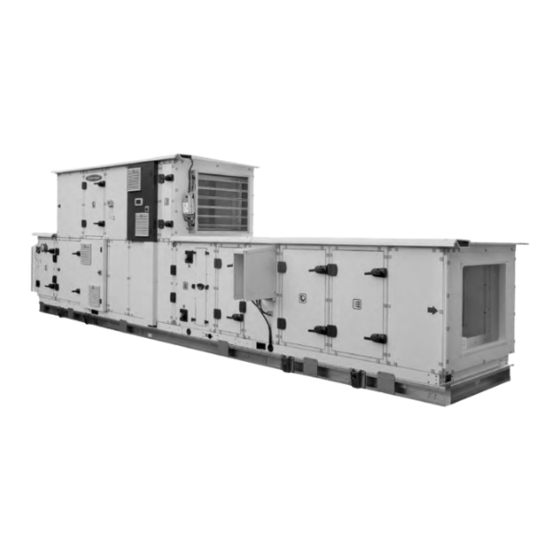
- Page 1 O P E R AT I O N A N D M A I N T E N A N C E I N S T R U C T I O N S Air handling unit 39CP Air flow: 1000 to 30,000 m Original document...
-
Page 2: Table Of Contents
CONTENTS 1 - GENERAL INFORMATION ................................4 1.1 - Intended use....................................4 1.2 - Documentation ..................................4 1.3 - Warranty ....................................4 2 - SAFETY INSTRUCTIONS ................................5 3 - REGULATIONS ..................................... 6 3.1 - General information ................................... 6 3.2 - Regulations ....................................6 3.3 - Accreditation .................................... - Page 3 CONTENTS 10 - OPERATION AND MAINTENANCE ............................62 10.1 - General recommendations for cleaning ..........................62 10.2 - Filters..................................... 62 10.3 - Fans ...................................... 63 10.4 - Heating/cooling coil ................................64 10.5 - Electric heater ..................................65 10.6 - Steam humidifier ................................... 66 10.7 - Damper and mixing ................................
-
Page 4: General Information
1 - GENERAL INFORMATION ■ Thank you for choosing our air handling unit. The design and construction of your unit are the fruit of all the expertise offered by our company's teams of technicians. 1.1 - Intended use ■ The air handling units are designed for use indoors or outdoors (canopy and roof option mandatory) ■... -
Page 5: Safety Instructions
2 - SAFETY INSTRUCTIONS ■ The air handling units are designed in compliance with recognised safety rules. ■ Unauthorised persons and the general public must be prevented from accessing this device. ■ These units must be used in perfect technical condition and within their field of application. ■... -
Page 6: Regulations
The Restriction of the Use of Certain Hazardous Substances in Electrical and Electronic Equipment Regulations 2012 The Ecodesign for Energy-Related Products and Energy Information Regulations 2019, and following amendments UK REACH Regulations 2019 UK Importer: Toshiba Carrier UK Ltd, Porsham Close, Roborough, Plymouth, PL6 7DB... -
Page 7: Accreditation
3 - REGULATIONS 3.3 - Accreditation ■ The following accreditation is required to work on the unit: - Electrical qualification (in accordance with regulations) for working near the unit or on the electrical components. ■ Technicians who install, commission, operate and service the unit must have received the necessary training and certification, understand the instructions given in this manual and be familiar with the specific technical characteristics of the installation site. -
Page 8: Identification
4 - IDENTIFICATION 4.1 - Data plate ■ Each unit has a manufacturer's name plate bearing an identification number and the unit designation. Make sure this information matches that on the order. Réf. Produit / Item Ref. Désignation / Description An / Year N. -
Page 9: Pictograms
4 - IDENTIFICATION 4.2 - Pictograms Heating coil Filter Electric heater Electrics box Cooling coil Steam humidifier Steam coil Stop-drop Adiabatic humidifier Discharge siphon Air flow Sound attenuator Coil outlet arrow DANGER D’INCENDIE F I L T R E S EMPOUSSIERES Coil inlet arrow Fire danger... -
Page 10: Shipping - Delivery - Handling
■ Upon delivery of the unit components, inspect the consignment in the presence of the driver. If any damage is observed, or if the delivery is incomplete, indicate this in the usual way on the delivery note and confirm to the carrier by registered letter within three days of the delivery date and send a copy to us. -
Page 11: Instructions For Lifting And Handling
5 - SHIPPING - DELIVERY - HANDLING NB: Terms such as "pending unwrapping" and "unit damaged but packaging in good condition" are not admissible by insurance companies. For any other problem, your contact will be able to explain the relevant procedure. 5.4 - Instructions for lifting and handling ■... - Page 12 5 - SHIPPING - DELIVERY - HANDLING 5.4.1 - SPECIAL FEATURE: STACKED plate heat exchanger THE AHU B P T1800 T2100 WARNING: ■ The block is transported on its side. It must be lifted onto its feet before being handled with a crane. ■...
-
Page 13: Anchoring Points For Handling
We recommend the use of shackles when handling these units. Ø35 Ø12.5 5.5.1 - Special feature of 39CP STAINLESS STEEL THE steel threaded brackets (red eyebolt mounting) must be removed: THREADED BRACKET These lifting lugs are used when placing blocks near each other, AND MUST NOT BE USED ONCE DISASSEMBLED. -
Page 14: Storage
5 - SHIPPING - DELIVERY - HANDLING Packaged unit on a frame: Ø35 5.6 - Storage ■ Do not remove the original packaging. ■ Do not remove the protective caps until you are ready to connect the coils. ■ The unit must be stored on a flat surface. ■... -
Page 15: Installation
6 - INSTALLATION 6.1 - Warning Before installing, make sure that the components are clean, and clean them if necessary. Warning! Follow the safety instructions (see § 2 - SAFETY INSTRUCTIONS). 6.2 - Selecting a location ■ Before setting up and connecting the unit, the installer must check the following points: - The unit's earthquake resistance has not been verified. - Page 16 6 - INSTALLATION Sound level ■ Our units are designed to operate quietly. ■ As soon as you begin designing your system, you should take into consideration the outdoor environment to estimate the radiated noise, and the building type for the noise transmitted through the air and by solid materials. ■...
- Page 17 6 - INSTALLATION BRACKET* Example (identical to Fig. 2) of stacked units Openings front view Anti-vibration mounts and counter frame fitted to ensure uniform load distribution LEVELLING ESSENTIAL To ensure correct sealing between the blocks...
- Page 18 6 - INSTALLATION ■ DIFFERENT WIDTHS: - To stack two units of different widths - AN INTERMEDIATE FRAME MUST BE FITTED* of the same width as the lower unit. (Load lowering) Not supplied INTERMEDIATE FRAME* STACKING NOT STACKING STACKING NOT AUTHORISED AUTHORISED AUTHORISED...
-
Page 19: Assembling The Blocks
6 - INSTALLATION 6.3 - Assembling the blocks Ensure sufficient servicing space to allow easy maintenance and assembly of the blocks. The air inlets must be capped if installation is interrupted. A waterproof film is recommended to prevent white rust. Electrical safety The components and cables must be selected in accordance with the regulations in force at the installation site. - Page 20 6 - INSTALLATION ■ Fit the 15 x 9 sealing gasket on the end partition of one block. To ensure a proper seal between two blocks, position the gasket on the aluminium profiled edge of one block as close as possible to the inside of the unit (illustrations below). Gasket Gasket Detail: gasket position...
- Page 21 6 - INSTALLATION ■ AHU with option T2-TB2. An additional 15 x 9 sealing gasket must be fitted to the same block, as close as possible to the outside of the unit. (see figures below). SINGLE PARTITION: WARNING: STANDARD BETWEEN SINGLE-FLOW OPTION T2 TB2 GASKET BLOCKS...
- Page 22 6 - INSTALLATION Accessories for bringing the blocks together To finish bringing the blocks together, 4 brackets are provided to be used simultaneously: 2 on the FRONT FACE and 2 on the REAR FACE. (figures 1 and 2 below). When bringing the blocks together, make sure the various cleats (2) fit together correctly. Finalise the assembly by screwing the connecting cleats together using the metric screw (3) + M8 nut (4) supplied in the kit.
-
Page 23: Options: Adjustable Feet, Risers And Risers + Cylinders
6 - INSTALLATION 6.4 - OPTIONS: Adjustable feet, risers and risers + cylinders Description Instructions 1. Remove the transport feet ADJUSTABLE FEET (cylinder with foot which is articulated and 2. Screw in the cylinders under the adjustable feet adjustable over 30 mm) 3. -
Page 24: Juxtapose Function Sealed Junction Special Features
6 - INSTALLATION 6.5 - JUXTAPOSE FUNCTION sealed junction special features WARNING: For a unit with the side-by-side plate heat exchanger function; ASSEMBLY MUST START WITH THE TWO BLOCKS OF THE SIDE-BY-SIDE PLATE HEAT EXCHANGER FUNCTION. The other blocks which make up the system will be assembled afterwards. Connecting the blocks: To guarantee the tightness between the flows. -
Page 25: Roof/Canopy (Accessories)
6 - INSTALLATION 6.6 - Roof/canopy (Accessories) Depending on the sizes and the options, the roof and canopy may be delivered on a pallet, or attached to one of the blocks (roof) or fitted in position (canopy). A roof supplied attached to a transport bracket on the front must be unpacked as shown in fig 1-2-3 Roofs packaged in plastic film Fig. - Page 26 6 - INSTALLATION Raceway cover Blanking covers Raceway gaskets (x2) Roof panel gasket Blanking cover gasket Connecting cover Gaskets (x2)
- Page 27 6 - INSTALLATION Roof panel mounting direction Roof panels Blanking Blanking cover cover without return bend Roof panel tightening direction DO NOT CLIMB ONTO THE ROOF PANELS Affixing to the omega brackets Inter-panel mounting A platform (not provided) may be positioned resting on the omega brackets to affix the roof panels.
- Page 28 6 - INSTALLATION JUXTAPOSE T1800 - T2100 FUNCTION SPECIAL FEATURE ASSEMBLY PROCEDURE for the ELECTRICAL CHANNEL (WITH or WITHOUT CONTROL UNIT) : x20 Ø 4.8x19 : x10 Ø 4.8x19 SEE DETAIL A : x16 Ø 4.8x19 ± 17cm ± 17cm DETAIL A SCALE 0.1...
- Page 29 6 - INSTALLATION ROOF: Assembly procedure: : x20 Ø 4.8x19 : x72 Ø 4.8x19...
- Page 30 6 - INSTALLATION GASKET STRIP 1.5 cm x 0.5 cm SEE DETAIL A DETAIL B : 1.5 cm x 0.5 cm : x54 Ø 5.5x13 DETAIL B DETAIL A SCALE 0.4 SCALE 0.3 GASKET STRIP 1.5 cm x 0.5 cm : 1.5 cm x 0.5 cm : x96 DETAIL C...
- Page 31 6 - INSTALLATION : x10 Ø 4.8x19 SEE DETAIL D GASKET STRIP 1.5 cm x 0.5 cm : 1.5 cm x 0.5 cm : x16 Ø 4.8x19 ± 17cm DETAIL D SCALE 0.1 : x 150 : x 118 : 1.5 cm x 0.5 cm...
-
Page 32: Connections
7 - CONNECTIONS 7.1 - Condensate drain siphon ■ Connecting the siphon Position, diameter and type of connector, see dimensional drawing. Outlet on the front panel: Threaded gas type steel connector. Outlet in frame: Smooth rubber female sleeve for 32 mm PVC bonding tube. It is recommended to use mastic to adhere the drain pan. -
Page 33: Droplet Eliminator
7 - CONNECTIONS 7.2.2 - STEAM coil 7.2.2.1 - Coil supply: ■ Follow the instructions on the labels: Inlet steam coil INLET TOP SECTION Outlet steam coil OUTLET Drainage of generated condensate Can only be drained via LOWER OUTLET 7.2.3 - Connection ■... - Page 34 7 - CONNECTIONS Connection types: ■ Heat exchangers with cylindrical threaded connectors with flat gaskets. - Always use two spanners when connecting or tightening the hydraulic couplings to avoid twisting the pipes and applying stress on the brazed areas. - Do not use zinc-coated or galvanised connectors or pipes. - WARNING: Check the compatibility of the materials (risk of electrolysis).
-
Page 35: Electric Heater
7 - CONNECTIONS ■ Exchangers with smooth braze-type INLET/OUTLET pipes. - WARNING: Be careful not to damage the bellows when brazing 1/ Damp cloth 2/ Brazing time < 10 s. 7.3.1 - Fitting the control valves (optional) Carry out installation in accordance with the plan supplied with the kit. The pipes and valves must not under any circumstances place any additional load on the unit. -
Page 36: Connecting The Disconnect Switches/Circuit Breakers
7 - CONNECTIONS Do not connect the electric heater to the ground (class 2 insulation). ■ For machines supplied with a control unit: - The heaters are supplied cabled to a specific unit nearby. - This unit must have a specific power supply. When selecting the cables, take into account the routing, the ambient operating temperature and the current of the connected heaters. -
Page 37: Connecting The Fans
7 - CONNECTIONS 7.5.2 - Connecting the 25A / 32A / 63A / 100A switches/circuit breakers ■ The cable used must be shielded to connect and ensure continuity of the disconnect switch/circuit breaker shielding. ■ Use the jumper supplied at delivery; insert the cable via the supplied packing box then affix the jumper (on the cable shielding) to the shielding plate in the switch. - Page 38 7 - CONNECTIONS "K1" relay output to indicate faults An external fault message is possible via the volt-free contact of the built-in relay (max. contact load Technical data and wiring diagram). Function in Factory settings for "K1": - During operation, the relay is excited and terminals "11" and "14" are bridged. In the event of a fault, the relay is deactivated (Diagnostic / Faults).
- Page 39 7 - CONNECTIONS 7.6.1.1 - Configuration with one fan motor assembly ■ Connection diagram: W1.78 ou/or W1.85 W1.79 ou/or W1.86 Wiring diagram for one EC motor fan only by air flow Customer W7.9 or W8.9 Motor start order Motor control 0-10V Signal Contact ouvert sur défaut Open contact on fault Max AC 250V - 2A...
- Page 40 7 - CONNECTIONS 7.6.1.2 - Connecting several EC fan motor assemblies without outdoor unit option ■ Connection diagram: EC motor fan n°1 EC motor fan n°2 EC motor fan n°8 The closer from the door access W7.1 or W8.1 W7.2 or W8.2 W7.8 or W8.8 Wiring diagram for several EN motor fan by air flow, without electrical box option selected...
- Page 41 7 - CONNECTIONS 7.6.1.4 - EC FAN MOTOR ASSEMBLY UNIT ELECTRICAL CONNECTION ELECTRICAL CONNECTION AT THE TOP 7.6.2 - AC MOTORS fan (plug fan and impeller) ■ Electrical connection: - A - Machine without variator and without proximity switch: To be connected directly to the terminal box for the motor(s). Europe zone: Pursuant to regulation 1253/2014 concerning the implementation of directive 2009/125/CE, an asynchronous motor may not be used without a speed variator.
- Page 42 7 - CONNECTIONS ■ B - Unit with proximity switch: - The motor(s) is/are prewired. - The connection is to the switch terminal block ■ Authorised tightening torques and maximum terminal connection sections: - See § 7.4.1 AC motor ■ C - Unit with frequency inverter - In the interest of shipping safety, the inverters are not installed at delivery.
-
Page 43: Filters
7 - CONNECTIONS 7.7 - Filters Warning! Follow the safety instructions (see § 2 - SAFETY INSTRUCTIONS). The filter cells are flammable products, and the fire risk may increase depending on the elements filtered by the medium. Keep the filters away from flames. Mounting, cleaning and replacement of filters pose risks of allergies and irritation of the skin, airways and eyes. -
Page 44: Standalone Steam Humidifier
7 - CONNECTIONS ■ Precautions: - Keep a spare set of filters in a clean, dry place. Filters are regulated components. Comply with the regulations, directives and standards in force at the installation site. 7.9 - Standalone steam humidifier ■ This section only covers the connection of the steam diffusion rails. ■... -
Page 45: Damper And Mixing
7 - CONNECTIONS ■ To ensure sufficient reliability, the recommended water quality values are shown in the table below: Recommended water quality Appearance Clear, colourless, no sediment pH value 7 to 8,5 Conductivity 30 mS/m max. Total hardness Max. 1,2 mol/m³ Max. - Page 46 7 - CONNECTIONS - External assembly on panel: Detail A - The servomotor should be affixed to the unit's external wall, - Tighten the clamp against the extension shaft, - Position and affix the plate on the unit's external wall to prevent the servomotor from rotating, - If the blades are not visible, a groove on the shaft of the dampers and extensions can be used to locate the open and closed positions of the dampers.
-
Page 47: Heat Recovery Units
7 - CONNECTIONS 7.11 - Heat recovery units Recommendation: Whether plate or rotary heat exchangers are used, air filtration is recommended to prevent premature fouling. 7.11.1 - Plate heat exchangers ■ Condensate draining connection - Refer to your dimensional drawing for the diameters of the connections and their positions. - Outlet on the front frame: threaded gas type steel connector. - Page 48 7 - CONNECTIONS ■ Cables recommended for connection: • Fixed speed motor: • Variable-speed motor: - 4G1.5 supply - 3G1.5 supply - 4x1 control (Max 2 A/250 V AC) Lowest voltage Highest voltage V2 W2 V2 W2 13 14 15 A1 A2 9 10 11 12 DELTA...
-
Page 49: Control
8 - CONTROL 8.1 - AHU with control ■ If the control is supplied by the manufacturer, refer to the manual provided with it. 8.2 - AHU without control ■ If the control is not supplied by the manufacturer, the manufacturer accepts no responsibility for any damage that may occur to the various controlled components due to faults or improper use. -
Page 50: Commissioning
9 - COMMISSIONING 9.1 - Siphon ■ The siphon must be activated during commissioning, or after each period of prolonged downtime. To do this, fill the drain pan with water and check that it drains quickly with no stagnant areas. ■... -
Page 51: Fan
9 - SYSTEM START-UP Activity Action, if required month months months months months Replace the corresponding Check for unacceptable contamination, damage (leaks) and odours filter Check the pressure differential Replace the filtration stage Maximum interval before replacement of the first filtration stage Maximum interval before replacement of the second filtration stage 9.4 - Fan 9.4.1 - Mains voltage... - Page 52 9 - SYSTEM START-UP ■ Check the condition of the flexible sleeves (AC motors) ■ Before use, check the wiring between the variator and the motor or between the distribution unit and the motors (see § 7 - CONNECTION) and the wiring diagrams provided. ■...
-
Page 53: Heating And Cooling Coil
9 - SYSTEM START-UP The belts have only been pretensioned for storage and shipping purposes. It is essential to tension them using the procedure described below: Deflection test: The belt tension must be checked and corrected using a suitable measuring instrument (tensiometer or dynamometer). Ea calculation: - Ea = (e x E)/100 = Deformation in mm for a pulley centre distance of 100 mm - e = Pulley centre distance in mm... - Page 54 9 - SYSTEM START-UP Recommendations concerning the quality of the water used for the heat exchangers: See table below or regulations in force at the installation site. The quality of the water or antifreeze mixture must be checked periodically Consequences in case Description Symbol Values...
-
Page 55: Electric Heater
9 - SYSTEM START-UP 9.6 - Electric heater 9.6.1 - Electric heater pre-commissioning checks: Warning! Follow the safety instructions (see § 2 - SAFETY INSTRUCTIONS). ■ Check for the presence of an air flow detection device. ■ Make sure the safety thermostats are electrically connected. Check the pin couplings (star as standard) as per the wiring diagram. ■... -
Page 56: Damper And Mixing
9 - SYSTEM START-UP 9.8 - Damper and mixing 9.8.1 - Condensate drain ■ In the mixing box: - Check the cleanliness of the drain pan - Fill the drain trap. - Check that the condensate is draining correctly 9.8.2 - System start-up Warning! Follow the safety instructions (see §... -
Page 57: Heat Recovery Unit
9 - SYSTEM START-UP 9.9 - Heat recovery unit 9.9.1 - Plate heat exchangers Warning! Follow the safety instructions (see § 2 - SAFETY INSTRUCTIONS). The sharp increase in the air pressure when the fire damper is closed may cause irreversible damage to the plate heat exchangers. - Page 58 9 - SYSTEM START-UP 9.9.2 - SPECIAL JUXTAPOSE FUNCTION Pressure connections: ■ WARNING: Connect up the flexible tubes for the pressure connections. JCX1 JCX2 (Left-hand block fresh air intake) (Right-hand block fresh air intake) (Top left-hand block exhaust air intake) (Top right-hand block exhaust air intake) JCC1 JCC2...
- Page 59 9 - SYSTEM START-UP 9.9.3 - Rotary heat exchanger system start-up Warning! Follow the safety instructions (see § 2 - SAFETY INSTRUCTIONS). ■ Wheel pre-start-up check - Cleanliness is a determining factor in the unit's performance, therefore check the condition of the fins, the fouling level, the corrosion level and for any damage.
-
Page 60: Check After Start-Up
9 - SYSTEM START-UP 9.9.6 - Positioning of the pressure tappings Warning! The supply for the pressure tappings is shown in the diagram below, for all flow directions: delta p Exhaust air Measurement points for delta p delta p A - B - C - D Glass pipe Fresh air delta p... - Page 61 9 - SYSTEM START-UP ■ Hydraulic noise check: In case of abnormal noise, check: - The operation of the air bleed valves on the coil manifolds or the system, - The condition of the water filters. - The installation of the 3-way valve. - The water flow rate value.
-
Page 62: Operation And Maintenance
10 - OPERATION AND MAINTENANCE 10.1 - General recommendations for cleaning To disinfect, use cleaning products which are compatible with the list of disinfectants approved by RKI (Robert Roch Institute) or VAH (Verbund für Angewandte Hygiene). Respect the contact times and concentrations indicated by the manufacturer. ■... -
Page 63: Fans
10 - OPERATION AND MAINTENANCE 10.3 - Fans 10.3.1 - Direct-drive fans Periodic maintenance ■ Every 3 months ■ Every month for ATEX units ■ Follow the instructions given in section 10.1 General recommendations for cleaning Warning! Follow the safety instructions (see § 2 - SAFETY INSTRUCTIONS). ■... -
Page 64: Heating/Cooling Coil
10 - OPERATION AND MAINTENANCE 10.4 - Heating/cooling coil ■ Assembly and disassembly of the coil: If the coil is located just upstream or downstream of a unit junction, first remove the connection cleats before removing the front face, then the retaining screws and the tube holders Notes: ■... -
Page 65: Electric Heater
10 - OPERATION AND MAINTENANCE ■ Coil maintenance - If the fins are damaged, straighten them using a comb suited to the width of the fins. - Instruction in case of low fouling level (non-clogging dust or dry residue) - Counter-flow supply air: dry air up to 30 bar. - Where possible, periodically reversing the flow of air generated by the fans can prevent this. -
Page 66: Steam Humidifier
10 - OPERATION AND MAINTENANCE ■ Numerous factors may lead to general overheating of the electrical components, resulting in activation of the thermostats. - Examples: • Powering up without ventilation, • Insufficient air flow, • Clogged filters, • Reversing the fan's direction of rotation, •... -
Page 67: Sound Attenuator
10 - OPERATION AND MAINTENANCE ■ For drain pan option: - Clean and disinfect the drain pans with a suitable product. ■ For siphon option: - The siphon must be activated during commissioning, or after each period of prolonged downtime. - The siphon level must be checked periodically. - Page 68 10 - OPERATION AND MAINTENANCE ■ Cleaning the exchanger: - For a low fouling level: dust removal with a vacuum cleaner is sufficient. In general, self cleaning, which results from the reversed cross flows of air, means there is no need for manual maintenance on the wheel, - For a medium fouling level (non-clogging dry residue): blowing against the normal flow direction may be necessary (compressed air used with precautions), - For a very high fouling level (clogging wet or greasy dust residue), use hot water and a gentle detergent.
-
Page 69: List Of Checks And Maintenance
10 - OPERATION AND MAINTENANCE 10.10 - List of checks and maintenance ■ Follow the instructions given in section 10.1 General recommendations for cleaning Varies Components To be checked 3 months 6 months Annual depending on use and wear Corrosion Casing Panels Gaskets... -
Page 70: Prolonged Downtime
10 - OPERATION AND MAINTENANCE Other components inside the air stream: ■ Glass pipes ■ Grommet ■ Pipe grommet ■ 90° elbows for pressure tapping ■ Plastic plugs for protecting screws ■ Electrical wiring ■ Anti-vibration mounts for fans These components can be removed and replaced in the event of microbial or fungal infection. It is recommended that they be replaced every 12 months. -
Page 71: Special Information For Atex Areas
11 - SPECIAL INFORMATION FOR ATEX AREAS In accordance with directive 2014/34/EU (explosive atmospheres) 11.1 - General information ■ Evaluation of the level of danger of explosion established in accordance with standards NF EN ISO 80079-36, NF EN ISO 80079-37 and EN 1127-1. ■... -
Page 72: Using Tools In An Explosive Atmosphere
11 - SPECIAL INFORMATION FOR ATEX ZONES 11.3.1 - Exchanger coils: ■ The temperature of the fluids circulating in the coils must not exceed the value given on the unit's name plate. ■ It must be below the surface temperature limit (or temperature class) corresponding to the ATEX atmosphere for which the unit is certified (see §... -
Page 73: Check - Periodic Inspections
11 - SPECIAL INFORMATION FOR ATEX ZONES 11.5 - Check - Periodic inspections 11.5.1 - Vibration of the unit ■ Dangers: - The vibration check detects: • Any wear to rotating parts. Any significant discrepancy in the vibration speeds may cause parts to come into contact with each other, which may spark an explosion;... -
Page 74: Atex Control Sheet
11 - SPECIAL INFORMATION FOR ATEX ZONES 11.6 - ATEX control sheet Number of Check or Initial Date hours of Type of operation Comments Approved Failed Test performed values service Vibration speed on fan and motor bearings. (According to standard ISO 14694) Ground strap between motor and fan... -
Page 75: Final Shut-Down
12 - FINAL SHUT-DOWN 12.1 - Shutting down ■ Separate the units from their energy sources, allow them to cool then drain them completely. 12.2 - Recommendations for disassembly ■ Handling operations must be carried out by qualified personnel using PPE. The PPE must comply with the safety rules. ■... - Page 76 Please contact your sales representative for more information. Order No.: EN7499511-08, 07.2023 - Supersedes order No.: EN7499511-07, 05.2022. Carrier S.C.S, Rte de Thil - 01120 Montluel - France. The manufacturer reserves the right to make changes to the product specifications without notice.
Need help?
Do you have a question about the 39CP and is the answer not in the manual?
Questions and answers