Table of Contents
Advertisement
Quick Links
Advertisement
Chapters
Table of Contents

Subscribe to Our Youtube Channel
Related Manuals for Asus RS720A-E12 Series


Summary of Contents for Asus RS720A-E12 Series
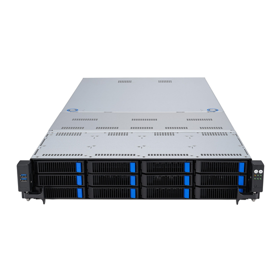
- Page 1 RS720A-E12 Series RS720A-E12-RS24U 2U Rackmount Server User Guide...
- Page 2 ASUSTeK COMPUTER INC. (“ASUS”). ASUS provides this manual “as is” without warranty of any kind, either express or implied, including but not limited to the implied warranties or conditions of merchantability or fitness for a particular purpose. In no...
-
Page 3: Table Of Contents
Contents Safety information ..................... vii About this guide ......................ix Chapter 1: Product Introduction System package contents ................. 1-2 Serial number label ..................1-3 System specifications ................1-4 Front panel features ................... 1-7 Rear panel features ..................1-8 Internal features ..................1-9 LED information .................. - Page 4 Storage devices..................2-22 2.6.1 Installing a 2.5” hot-swap SATA/SAS/NVMe storage device ..2-23 2.6.2 Installing a 2.5” storage device to the rear bay ......2-24 Expansion slot ..................2-25 2.7.1 Installing an expansion card to riser card bracket 1 (for standard model) ..............2-27 2.7.2 Installing an expansion card to riser card bracket 2 and 3 (for standard model) ..............
- Page 5 Chapter 5: BIOS Setup Managing and updating your BIOS ............5-2 5.1.1 ASUS CrashFree BIOS 3 utility........... 5-2 5.1.2 ASUS EZ Flash Utility ..............5-3 5.1.3 BUPDATER utility ............... 5-4 BIOS setup program .................. 5-6 5.2.1 BIOS menu screen ..............5-7 5.2.2...
- Page 6 Event Logs menu ..................5-43 5.9.1 Change Smbios Event Log Settings ......... 5-44 5.9.2 View Smbios Event Log ............5-45 5.10 Server Mgmt menu ................... 5-46 5.10.1 System Event Log ..............5-47 5.10.2 BMC network configuration ............5-48 5.10.3 View System Event Log ............5-50 5.11 Exit menu ....................
-
Page 7: Safety Information
Safety information Electrical Safety • Before installing or removing signal cables, ensure that the power cables for the system unit and all attached devices are unplugged. • To prevent electrical shock hazard, disconnect the power cable from the electrical outlet before relocating the system. - Page 8 Lithium-Ion Battery Warning CAUTION! Danger of explosion if battery is incorrectly replaced. Replace only with the same or equivalent type recommended by the manufacturer. Dispose of used batteries according to the manufacturer’s instructions. Heavy System CAUTION! This server system is heavy. Ask for assistance when moving or carrying the system.
-
Page 9: About This Guide
About this guide Audience This user guide is intended for system integrators, and experienced users with at least basic knowledge of configuring a server. Contents This guide contains the following parts: Chapter 1: Product Introduction This chapter describes the general features of the server, including sections on front panel and rear panel specifications. - Page 10 Refer to the following sources for additional information and for product and software updates. ASUS Control Center (ACC) user guide This manual tells how to set up and use the proprietary ASUS server management utility. Visit asuscontrolcenter.asus.com for more information.
-
Page 11: Chapter 1: Product Introduction
Chapter 1: Product Introduction Product Introduction This chapter describes the general features of the server. It includes sections on front panel and rear panel specifications. -
Page 12: System Package Contents
System package contents Check your system package for the following items. RS720A-E12-RS24U Chassis ASUS R12F 2U Rackmount Chassis Motherboard ASUS K14PP-D24 Server Board 1 x 80PLUS Power Supply 1 x 2.5-inch Storage Device Backplane 24 x 2.5-inch Storage Device Trays or Dummy Trays... -
Page 13: Serial Number Label
The product’s serial number contains 12 characters, such as xxSxxxxxxxxx, and printed on the sticker adhered to the server's front cover. The correct serial number of the product is required if you need to request for support from the ASUS Technical Support team. RESET RS720A-E12-RS24U... -
Page 14: System Specifications
System specifications The ASUS RS720A-E12 Series features the ASUS K14PP-D24 server board. The server supports AMD EPYC™ 9004 series processors, plus other latest technologies through the chipsets onboard. Model Name RS720A-E12-RS24U Motherboard K14PP-D24 2 x Socket SP5 (LGA 6096) Processor Support AMD EPYC™... - Page 15 * The number of LAN LEDs available depends on the LAN Controller card installed. Rear Switch/LED: 1 x Port 80 LED (Q-Code) 1 x Power Switch w/ LED 1 x Location LED 1 x Message LED (continued on the next page) ASUS RS720A-E12 Series...
- Page 16 Enterprise Linux ® SuSE Linux Enterprise Server ® CentOS OS Support Ubuntu Vmware * Please find the latest OS support from https://www.asus.com/ event/Server/OS_support_list/OS.html Software ASUS Control Center Management Out of Band Remote Solution On-Board ASMB11-iKVM for KVM-over-IP Management Regulatory Compliance BSMI, CE, CB, C-Tick, FCC(Class A) 840mm x 449mm x 88.1mm (2U)
-
Page 17: Front Panel Features
Bay 1 to bay 8 supports NVMe/SATA/SAS. SAS support requires optional HBA/RAID card. For extra security, a front bezel (purchased separately) can be installed to prevent unauthorized physical access to the hard drives and power button. Bezel release latch Front bezel Bezel keylock RESET ASUS RS720A-E12 Series... -
Page 18: Rear Panel Features
Expansion slot VGA port • Mgmt LAN port is for ASUS ASMB11-iKVM only. • The Q-Code LED provides the most probable cause of an error code as a starting point for troubleshooting. The actual cause may vary from case to case. -
Page 19: Internal Features
24 x 2.5” storage device trays A protection film is pre-attached to the front cover before shipping. Please remove the protection film before turning on the system for proper heat dissipation. WARNING HAZARDOUS MOVING PARTS KEEP FINGERS AND OTHER BODY PARTS AWAY ASUS RS720A-E12 Series... - Page 20 GPU model Riser card bracket OCP Adapter (hidden, optional) Redundant Power supply (hidden) PCIe riser card (hidden) ASUS K14PP-D24 Server Board System fans NVMe/SATA/SAS back panel Front USB Board Asset tag (hidden) Front panel (hidden) 24 x 2.5”storage device trays External Fan* (optional) Ensure to install the external fan when GPU is installed on slot 3 &...
-
Page 21: Led Information
No LAN connection LAN LEDs Blinking LAN is transmitting or receiving data LAN connection is present Location switch is pressed Location LED Normal status (Press the location switch again to turn off) ASUS RS720A-E12 Series 1-11... -
Page 22: Storage Device Status Led
1.7.2 Storage device status LED Green LED Red LED RESET Storage Device LED Description GREEN SATA/SAS storage device power ON Storage device has failed and should be swapped immediately (For RAID card) GREEN/ Blinking RAID rebuilding (For RAID card) GREEN/ Blinking Locate (For RAID card) GREEN/... -
Page 23: Lan (Rj-45) Leds
X710-AT2 10GbE LAN port LEDs ® ACT/LINK LED SPEED LED ACT / LINK LED SPEED LED Status Description Status Description No link 10Mbps / 100 Mbps connection GREEN Linked ORANGE 1 Gbps connection BLINKING Data activity GREEN 10 Gbps connection ASUS RS720A-E12 Series 1-13... -
Page 24: Rear Panel Leds
1.7.4 Rear panel LEDs Power LED Location LED Q-Code LED Display status Description Power LED System power ON Normal status Location LED Location switch is pressed (Press the location switch again to turn off) 1-14 Chapter 1: Product Introduction... -
Page 25: Q-Code Table
Attempt to unmap permanently mapped TLB to PSP secure region 0x39 error Unable to map an SMN address to AXI space 0x3A error Unable to map a SYSHUB address to AXI space (continued on the next page) ASUS RS720A-E12 Series 1-15... - Page 26 Action PHASE POST CODE TYPE DESCRIPTION 0x3B error The count of CCXs or cores provided by bootrom is not consistent 0x3C error Uncompressed image size doesn't match value in compressed header 0x3D error Compressed option used in case where not supported 0x3E error Fuse info on all dies don't match...
- Page 27 Inline AES key wrapper stored in DRAM 0xB7 error Completed FW Validation step 0xB8 error Completed FW Validation step 0xB9 error BIOS copy from SPI to DRAM complete 0xBA error Completed FW Validation step (continued on the next page) ASUS RS720A-E12 Series 1-17...
- Page 28 Action PHASE POST CODE TYPE DESCRIPTION 0xBB error BIOS load process fully complete 0xBC error Bootloader successfully release x86 0xBD error Early Secure Debug completed 0xBE error GetFWVersion command received from BIOS is completed 0xBF error SMIInfo command received from BIOS is completed 0xC0 error Successfully entered WarmBootResume()
- Page 29 Progress BIOS Setup Utility password verify 0xA9 Progress BIOS Setup Utility start 0xAB Progress BIOS Setup Utility input wait 0xAD Progress Ready to boot event 0xAA Progress APIC mode Operating system phase 0xAC Progress PIC mode ASUS RS720A-E12 Series 1-19...
- Page 30 1-20 Chapter 1: Product Introduction...
-
Page 31: Chapter 2: Hardware Information
Chapter 2: Hardware Information Hardware Information This chapter lists the hardware setup procedures that you have to perform when installing or removing system components. -
Page 32: Chassis Cover
Chassis cover 2.1.1 Removing the rear cover Remove the two (2) screws on both sides of the rear cover with a Phillips screwdriver. Push and hold the cover buttons down on the rear cover. Slide the rear cover towards the rear panel to disengage it from the chassis, then lift the rear cover to completely remove it from the chassis. -
Page 33: Removing The Mid Cover
Remove the two (2) screws on both sides of the mid cover with a Phillips screwdriver. Push the buttons on both sides to release the mid cover from the chassis. Lift the mid cover to completely remove it from the chassis. ASUS RS720-E12 Series... -
Page 34: Air Ducts
Air ducts 2.2.1 Removing the air duct (for standard model) Remove two (2) screws from the air duct. Gently lift the air duct vertically out of the chassis. Chapter 2: Hardware Information... -
Page 35: Removing The Air Duct (For Gpu Model)
Please refer to steps 1 and 2 of Installing an expansion card to riser card bracket 1 (for GPU model), and Installing an expansion card to riser card bracket 2 and 3 (for GPU model) sections to remove the riser card brackets. Gently lift the air ducts vertically out of the chassis. ASUS RS720-E12 Series... -
Page 36: Installing The Air Duct (For Standard Model)
2.2.3 Installing the air duct (for standard model) Align the air duct along the edges of the DIMM slots, and then place the air duct in the chassis. Secure the air ducts to the chassis using two (2) screws. Chapter 2: Hardware Information... -
Page 37: Installing The Air Duct (For Gpu Model)
Please refer to steps 15 and 16 of Installing an expansion card to riser card bracket 1 (for GPU model), and steps 10 and 11 of Installing an expansion card to riser card bracket 2 and 3 (for GPU model) sections to install the riser card brackets. ASUS RS720-E12 Series... -
Page 38: Central Processing Unit (Cpu)
Contact your retailer immediately if the PnP cap is missing, or if you see any damage to the PnP cap/socket contacts/motherboard components. ASUS will shoulder the cost of repair only if the damage is shipment/ transit-related. - Page 39 A torque value of 13.5±1.0kg- cm (11.7±0.9 lbf-in) is recommended . Load plate Lift open the rail frame. External cap Rail frame External cap Slide the external cap out of the rail frame. Rail frame PnP cap ASUS RS720-E12 Series...
- Page 40 Slide the carrier frame with CPU into the rail frame, then remove the PnP cap. The carrier frame with CPU fits in only one correct orientation. DO NOT force the carrier frame with CPU into the rail frame. Gently close the rail frame just enough to let it sit on top of the CPU socket.
-
Page 41: Installing The Heatsink (For Gpu Model)
When the six screws are attached, tighten them one by one in the same order to completely secure the heatsink. The heatsink screws are T20 models. A torque value of 13.5±1.0kg-cm (11.7±0.9 lbf-in) is recommended. ASUS RS720-E12 Series 2-11... - Page 42 Tighten the remaining heatsink screws to secure the heatsink to the motherboard. A torque value of 5.8±0.3 kgf-cm (5.0±0.3 lbf-in) is recommended. Chapter 2: Hardware Information 2-12...
-
Page 43: Installing The Heatsink (For Standard Model)
When the six screws are attached, tighten them one by one in the same order to completely secure the heatsink. The heatsink screws are T20 models. A torque value of 13.5±1.0kg-cm (11.7±0.9 lbf-in) is recommended. ASUS RS720-E12 Series 2-13... -
Page 44: System Memory
System memory 2.4.1 Overview The motherboard comes with 24 Double Data Rate 5 (DDR5) Dual Inline Memory Modules (DIMM) sockets. The figure illustrates the location of the DDR5 DIMM sockets: Chapter 2: Hardware Information 2-14... -
Page 45: Memory Configurations
DIMMS, you can use the recommended memory configuration in this section for reference. • Refer to ASUS Server AVL for the updated list of compatible DIMMs. • Always install DIMMs with the same CAS latency. For optimum compatibility, it is recommended that you obtain memory modules from the same vendor. - Page 46 Recommended memory configuration for 2 CPU Configuration Dual CPU configuration DIMMs CPU1 • • • • • • • • • • • • • • • • • • • • • • • • • • • • •...
-
Page 47: Installing A Dimm
DIMM. Remove the DIMM from the socket. Support the DIMM lightly with your fingers when pressing the retaining clips. The DIMM might get damaged when it flips out with extra force. ASUS RS720-E12 Series 2-17... -
Page 48: Optional) Front Bezel
(optional) Front bezel For extra security, a front bezel (purchased separately) can be installed to prevent unauthorized physical access to the hard drives and power button. 2.5.1 Removing the front bezel Push the bezel release latch of the front bezel towards the right to unlock the bezel. Slide the front bezel towards the left of the system to detach the front bezel, then remove it from the system. -
Page 49: Installing The Front Bezel
Installing the front bezel Align the two (2) right notches on the front bezel to the notch holes on the right front panel. Attach the right side of the front bezel to the right front panel. ASUS RS720-E12 Series 2-19... - Page 50 Push the left side of the front bezel towards the left USB panel. Make sure the two (2) left notches on the front bezel are aligned with the notch holes on the left USB panel, then push and attach the front bezel to the left USB panel. Make sure the bezel release latch is in the unlock state (pushed to the right) before attaching the front bezel to the left USB panel.
- Page 51 Push the bezel release latch of the front bezel towards the left to lock the bezel. ASUS RS720-E12 Series 2-21...
-
Page 52: Storage Devices
Storage devices The system supports twenty-four (24) 2.5” hot-swap NVMe storage devices or up to 8 x NVMe/SATA/SAS + 16 x NVMe storage devices. The storage device installed on the storage device tray connects to the motherboard SATA/SAS/NVMe ports via the SATA/SAS/NVMe backplane. -
Page 53: Installing A 2.5" Hot-Swap Sata/Sas/Nvme Storage Device
When installed, the SATA/SAS/NVMe connector on the storage device connects to the SATA/SAS/NVMe interface on the backplane. • The storage device tray is correctly placed when its front edge aligns with the bay edge. Repeat steps 1 to 4 to install the other SATA/SAS/NVMe storage devices. ASUS RS720-E12 Series 2-23... -
Page 54: Installing A 2.5" Storage Device To The Rear Bay
2.6.2 Installing a 2.5” storage device to the rear bay Press the spring lock then pull the tray lever outward to Tray lever Spring lock release the storage device tray. The storage device tray ejects slightly after you pull out the lever. Firmly hold the tray lever and pull the storage device tray out of the bay. -
Page 55: Expansion Slot
Slot 2 Slot 3 OCP 3.0 Slot 4 x8 (ASUS PIKE II card) x8 (ASUS PIKE II card) Riser card bracket 2 Riser card bracket 2 supports PCIe Gen4 slots 5-6 top to bottom. Slot 5 can be auto-switch to x16 mode when x16 card is populated whereas slot 6 will be disabled. - Page 56 Riser card bracket 4 Riser card bracket 4 supports PCIe Gen4 slots 7-8 top to bottom. Slot 7 can be auto-switch to x16 mode when x16 card is populated whereas slot 8 will be disabled. PCIe slot Operation mode Slot 7 Slot 8 Chapter 2: Hardware Information 2-26...
-
Page 57: Installing An Expansion Card To Riser Card Bracket 1
PCIe slot on the motherboard. Place the riser card bracket on a flat and stable surface. Flip the PCIe lock open. Remove the metal cover(s) of the slot(s) you wish to install a PCIe expansion card to. ASUS RS720-E12 Series 2-27... - Page 58 Install the PCIe expansion card into the riser card bracket. Flip the metal bracket lock back to secure the PCIe expansion card to the riser card bracket. Install the riser card bracket and the expansion cards assembly into the PCIe slot on the motherboard.
- Page 59 Lift the riser card out of the chassis by firmly holding it by the tab and pulling it upwards to detach it from the PCIe slot on the motherboard. Riser card bracket 2 Riser card bracket 3 ASUS RS720-E12 Series 2-29...
- Page 60 Place the riser card bracket on a flat and stable surface. Flip the PCIe lock open. Remove the metal cover(s) of the slot(s) you wish to install a PCIe expansion card to. Install the PCIe expansion card into the riser card bracket. Flip the metal bracket lock back to secure the PCIe expansion card to the riser card bracket.
- Page 61 Install the riser card bracket and expansion card assembly into the PCIe slot on the motherboard. Ensure that the golden connectors of the riser card bracket is firmly seated in place. Secure the riser card bracket to the chassis with the thumbscrew. Riser card bracket 2 Riser card bracket 3 ASUS RS720-E12 Series 2-31...
-
Page 62: (For Gpu Model)
2.7.3 Installing a GPU card to riser card bracket 1 (for GPU model) To install a passive GPU (FH/FL) card to the riser card bracket 1: Loosen the thumbscrew securing the riser card bracket to the chassis. Lift the riser card out of the chassis by firmly holding it by the tab and pulling it upwards to detach it from the PCIe slot on the motherboard. - Page 63 Install the GPU card into the riser card bracket. Flip the PCIe lock back to secure the GPU card to the riser card bracket. Connect the power cable from the GPU card to the power connector on the PCIe riser card. ASUS RS720-E12 Series 2-33...
- Page 64 Install the riser card bracket and the GPU cards assembly into the PCIe slot on the motherboard. Ensure that the golden connectors of the riser card bracket is firmly seated in place. Secure the riser card bracket to the chassis with the thumbscrew. Chapter 2: Hardware Information 2-34...
-
Page 65: Installing A Gpu Card To Riser Card Bracket 2 And 3
Lift the riser card out of the chassis by firmly holding it by the tab and pulling it upwards to detach it from the PCIe slot on the motherboard. Riser card bracket 2 Riser card bracket 3 ASUS RS720-E12 Series 2-35... - Page 66 Place the riser card bracket on a flat and stable surface. Connect the power cable to the GPU card, and ensure to place the cable through the opening of the GPU air duct. Secure the GPU air duct to the GPU card with the screws. Flip the PCIe lock open.
- Page 67 Install the riser card bracket and the GPU card assembly into the PCIe slot on the motherboard. Ensure that the golden connectors of the riser card bracket is firmly seated in place. Secure the riser card bracket to the chassis with the thumbscrew. Riser card bracket 2 ASUS RS720-E12 Series 2-37...
- Page 68 Riser card bracket 3 Chapter 2: Hardware Information 2-38...
-
Page 69: Installing An Expansion Card To Riser Bracket 4
(for GPU model), and Installing an expansion card to riser card bracket 2 and 3 (for GPU model) sections. Lift the riser card out of the chassis by firmly holding it by the tab and pulling it upwards to detach it from the PCIe slot on the motherboard. ASUS RS720-E12 Series 2-39... - Page 70 Place the riser card bracket on a flat and stable surface. Flip the PCIe lock open (A) then remove the metal bracket (B). Install the expansion card to the RS2_PCIE1 slot on the riser bracket (A), and then flip the PCIe lock back to secure the card (B). Chapter 2: Hardware Information 2-40...
- Page 71 Please refer to steps 15 and 16 of Installing an expansion card to riser card bracket 1 (for GPU model), and steps 10 and 11 of Installing an expansion card to riser card bracket 2 and 3 (for GPU model) sections. ASUS RS720-E12 Series 2-41...
-
Page 72: Installing An Ethernet Expansion Card To Riser Bracket 4
2.7.6 Installing an ethernet expansion card to riser bracket 4 ® The pre-installed riser card bracket 4 can support a 4-port Intel I350-AM4 1G LAN controller ® expansion card or 2-port Intel X710-AT2 Gigabit 10G LAN controller expansion card. ® Do not install a 4-port Intel I350-AM4 1G LAN controller expansion card if you plan to install an external rear fan. -
Page 73: Replacing An Hba/Raid Expansion Card To Riser Bracket 4
Prepare your HBA/RAID card. Remove the two (2) screws on the HBA/RAID card securing the metal bracket (A), then remove the metal bracket (B). Insert the HBA/RAID card to the RS3_PCIE1 slot on the riser card bracket. ASUS RS720-E12 Series 2-43... -
Page 74: Installing The Cache Vault Power Module
2.7.8 Installing the Cache Vault Power Module The cache vault power module is required for selected HBA/RAID card models. You may install the cache vault power module to the riser bracket 1 or riser bracket 4. Please refer to the steps below to install the cache vault power module to your server system. The cache vault power module can only be installed to riser bracket 1 of the standard model or standard model with rear storage bay. - Page 75 Align the three screw holes on the Cache Vault Power Module clip with the three screw holes on the riser bracket, then secure the clip with the three bundled screws and hex nuts. Align and install the Cache Vault Power Module into the Cache Vault Power Module clip. ASUS RS720-E12 Series 2-45...
- Page 76 Connect the Cache Vault Power Module to the S-CAP connector on the PIKE II card or HBA/RAID card. Follow step 6 of Installing an expansion card to riser bracket 4 to install riser card bracket 4 into the chassis. Chapter 2: Hardware Information 2-46...
-
Page 77: Installing An Ocp 3.0 Card
Insert the OCP 3.0 card into the OCP 3.0 slot from the rear of the system. Make sure the OCP 3.0 card is seated securely in the OCP 3.0 slot, and then secure it using the thumbscrew. ASUS RS720-E12 Series 2-47... -
Page 78: Installing An M.2 (Ngff) Card
2.7.10 Installing an M.2 (NGFF) card You may install M.2 cards (supports 2260, 2280) to the onboard M.2 (NGFF) slots on the motherboard. Follow steps 1-3 of Installing an expansion card to riser bracket 4 to remove riser card bracket 4 from the chassis. Locate the M.2 slots (NGFF1 / NGFF2) on the motherboard. - Page 79 Install your M.2 to the M.2 slot. Secure your M.2 using the bundled screw stand’s screw. For 2260 length Install the bundled screw stand to the M.2 length screw hole you wish to install your M.2 to. ASUS RS720-E12 Series 2-49...
- Page 80 Install your M.2 to the M.2 slot. Secure your M.2 using the bundled screw stand’s screw. For 2242 length Remove the M.2 rubber. Install the bundled screw stand to the M.2 length screw hole you wish to install your M.2 to. Chapter 2: Hardware Information 2-50...
- Page 81 Install your M.2 to the M.2 slot. Secure your M.2 using the bundled screw stand’s screw. Repeat step 3 if you have another M.2 card to install. ASUS RS720-E12 Series 2-51...
-
Page 82: Configuring An Expansion Card
2.7.11 Configuring an expansion card After installing an expansion card, configure it by adjusting the software settings. Turn on the system and change the necessary BIOS settings, if any. Refer to the BIOS Setup chapter for more information on BIOS setup. Assign an IRQ to the card. -
Page 83: Cable Connections
8-pin BPPWR1, BPPWR2, and BPPWR3 power connectors (connected to backplane) Panel connector (connected to front I/O board) System fan connectors MCIOPCIE1, MCIOPCIE2, MCIOPCIE3, and MCIOPCIE4 MCIO PCIe connectors (connected to backplane) SLMPCIE_SATA1 SlimSATA connector (connected to backplane) ASUS RS720-E12 Series 2-53... -
Page 84: Backplane Cabling
Backplane cabling Connects to mini-SAS HD connectors Connects to BPPWR3 Connects to CB board#2 Connects to CB board#1 Connects to BPPWR4 on motherboard for NVMe storage functions for NVMe storage functions on motherboard Connects to BPPWR1 Connects to BPPWR1 on motherboard on motherboard CB board#2 CB board#1... -
Page 85: Storage Device Configuration And Cabling
Bay 18 Bay 20 Bay 22 Bay 24 • Bays 1 to 8 support NVMe/SATA/SAS. SAS support requires an optional HBA/RAID card. • Bays 9 to 12 support NVMe/SATA. • All bays support 2.5” drives with trays. ASUS RS720-E12 Series 2-55... -
Page 86: 24 X Nvme + 8 X Sata Storage Device Configuration And Cabling
2.10.1 24 x NVMe + 8 x SATA storage device configuration and cabling The illustrations in this section are for reference only and may vary between models. Install the storage devices into the supported bays. Refer to Storage Devices for details on how to install storage devices. NVMe/SATA NVMe/SATA NVMe... -
Page 87: Removable/Optional Components
You may need to remove previously installed component or factory shipped components when installing optional components. 2.11.1 System fans To remove the system fans: Locate the fan you want to replace. Press the retaining clip (A) and lift upward (B) to remove the fan. ASUS RS720-E12 Series 2-57... - Page 88 To reinstall the system fans: Prepare the fan with the same model and size. Install the fan to the fan cage. The fan can only be installed in one direction. If the fan cannot be installed, turn it around and try again. Chapter 2: Hardware Information 2-58...
-
Page 89: Redundant Power Supply Module
Pull the power supply module out of the system chassis. Module lever PSU latch Prepare the replacement power supply module. Insert the replacement power supply module into the chassis then push it inwards until the latch locks into place. ASUS RS720-E12 Series 2-59... - Page 90 Chapter 2: Hardware Information 2-60...
-
Page 91: Chapter 3: Installation Options
Chapter 3: Installation Options Installation Options This chapter describes how to install the optional components and devices into the barebone server. -
Page 92: Tool-Less Friction Rail Kit
Tool-less Friction Rail Kit The tool-less design of the rail kit allows you to easily install the rack rails into the server rack without the need for additional tools. The kit also comes with a metal stopping bracket that can be installed to provide additional support and stability to the server. The tool-less rail kit package includes the following: Fixing latches Set of screws... - Page 93 Press the spring lock on the other end of rail then insert the stud into the mounting hole on the rack post. Extend the rack rail, if necessary. Perform steps 3 to 4 for the other rack rail. Ensure that the installed rack rails (left and right) are aligned, secured, and stable in place. ASUS RS720A-E12 Series...
-
Page 94: Rail Kit Dimensions
Lift the server chassis and insert it into the rack rail. • Ensure that the rack rail cabinet and the rack posts are stable and standing firmly on a level surface. • We strongly recommend that at least two able-bodied persons perform the steps described in this guide. -
Page 95: Ball Bearing Rail Kit
2 x M5X13.5L extended nuts • The bundled screw package includes different types of screws for you to choose from, not all screws are required for the installation. • Package content and specifications are subject to change without notice. ASUS RS720A-E12 Series... - Page 96 3.2.1 Attaching the rack rails • Ensure that the rack rail cabinet and the rack posts are stable and standing firmly on a level surface. • We strongly recommend that at least two able-bodied persons perform the steps described in this guide. •...
- Page 97 The blue release tab is available on 1200 mm rack rails. This blue release tab is used to further extend or retract the inner rail. Repeat steps 2 to 5 for the other rack rail. Ensure that the installed rack rails (left and right) are aligned, secured, and stable in place. ASUS RS720A-E12 Series...
- Page 98 Remove the three (3) screws from both left and right sides of the server system chassis, then remove the metal plate. The illustration below only shows one side of the server system chassis, but the screws on the other side should be at the same place. Metal plate Align the inner rails with the studs on both sides of the server system, install the inner rails to the server system, then slide the inner rails toward the rear of the server system...
- Page 99 Inner rail Intermediate rail Blue release tab White release tab The blue release tab is available on 1200 mm rack rails. This blue release tab is used to further extend or retract the inner rail. ASUS RS720A-E12 Series...
- Page 100 RESET Chapter 3: Installation Options 3-10...
-
Page 101: Chapter 4: Motherboard Information
Chapter 4: Motherboard Information Motherboard Information This chapter includes the motherboard layout and brief descriptions of the jumpers and internal connectors. -
Page 102: Motherboard Layout
Motherboard layout Chapter 4: Motherboard Information... - Page 103 Clear RTC RAM (3-pin CLRTC1) VGA controller setting (3-pin VGA_SW1) Baseboard Management Controller setting (3-pin BMC_EN1) DMLAN setting (3-pin DM_IP_SEL1) IPMI SW setting (3-pin IPMI_SW1) Smart Ride Through (SmaRT) setting (3-pin SMART_PSU1) LANNCSI setting (3-pin LANNCSI_SEL1) 4-10 4-10 4-11 ASUS RS720A-E12 Series...
- Page 104 Internal connectors Page SlimPCIe SATA connector (SLMPCIE_SATA1) 4-15 MCIO PCIe connector (MCIOPCIE1-4) 4-15 USB 3.2 Gen 1 connector (U31G1_34; U31G1_5) 4-16 Chassis Intrusion (2-pin INTRUSION1) 4-16 Serial port connector (10-1 pin COM1) 4-17 System fan connectors (6-pin FRNT_FAN1-9; REAR_FAN1-2) 4-17 TPM connector (14-1 pin TPM1) 4-18 M.2 (NGFF) card connector (NGFF1-2)
-
Page 105: Central Processing Unit (Cpu)
The motherboard comes with a surface mount SP5 socket designed for the AMD EPYC™ 7004 Series Family processors. Dual Inline Memory Module (DIMM) The motherboard comes with 24 Double Data Rate 5 (DDR5) Dual Inline Memory Modules (DIMM) sockets. ASUS RS720A-E12 Series... -
Page 106: Jumpers
Jumpers Clear RTC RAM (3-pin CLRTC1) This jumper allows you to clear the Real Time Clock (RTC) RAM in CMOS. You can clear the CMOS memory of date, time, and system setup parameters by erasing the CMOS RTC RAM data. The onboard button cell battery powers the RAM data in CMOS, which include system setup information such as system passwords. -
Page 107: Vga Controller Setting (3-Pin Vga_Sw1)
1–2 to activate the VGA feature. Baseboard Management Controller setting (3-pin BMC_EN1) This jumper allows you to enable (default) or disable on-board BMC. Ensure to set this BMC jumper to enabled to avoid system fan control and hardware monitor error. ASUS RS720A-E12 Series... -
Page 108: Dmlan Setting (3-Pin Dm_Ip_Sel1)
DMLAN setting (3-pin DM_IP_SEL1) This jumper allows you to select the DMLAN setting. Set to pins 2-3 to force the DMLAN IP to static mode (IP=10.10.10.10, submask=255.255.255.0). IPMI SW setting (3-pin IPMI_SW1) This jumper allows you to select which protocol in the GPU sensor to function. Chapter 4: Motherboard Information... -
Page 109: Smart Ride Through (Smart) Setting (3-Pin Smart_Psu1)
This feature is enabled by default. Set to pins 2-3 to disable it. When enabled, SmaRT allows uninterrupted operation of the system during an AC loss event. LANNCSI setting (3-pin LANNCSI_SEL1) This jumper allows you to select which LAN NCSI to enable. ASUS RS720A-E12 Series... - Page 110 Heatsink Type setting (3-pin HS_TYPE1) This jumper should be set according to the type of heatsink installed. ??? (3-pin CPU_DEBUGUART1) 4-10 Chapter 4: Motherboard Information...
- Page 111 ??? (3-pin BMC_JTAG_EN1) ??? (3-pin RS24U_J1) ASUS RS720A-E12 Series 4-11...
-
Page 112: Internal Leds
Internal LEDs Standby Power LED (SBPWR1) The motherboard comes with a standby power LED. The green LED lights up to indicate that the system is ON, in sleep mode, or in soft-off mode. This is a reminder that you should shut down the system and unplug the power cable before removing or plugging in any motherboard component. - Page 113 Message LED (MESLED) This onboard LED lights up red when there is a BMC event log generated. ASUS RS720A-E12 Series 4-13...
-
Page 114: Internal Connectors
Internal connectors SlimPCIe SATA connector (SLMPCIE_SATA1) This motherboard comes with Slim SATA connectors, the storage technology that supports Serial ATA. Each connector supports up to two devices. MCIO PCIe connector (MCIOPCIE1-4) Connects the PCIe signal to the riser card or NVMe port on the backplane. 4-14 Chapter 4: Motherboard Information... -
Page 115: Usb 3.2 Gen 1 Connector (U31G1_34; U31G1_5)
When you remove any chassis component, the sensor triggers and sends a high level signal to these leads to record a chassis intrusion event. The default setting is to short the CHASSIS# and the GND pin by a jumper cap to disable the function. ASUS RS720A-E12 Series 4-15... -
Page 116: Serial Port Connector (10-1 Pin Com1)
Serial Port connector (10-1 pin COM1) This connector is for a serial (COM) port. Connect the serial port module cable to this connector, then install the module to a slot opening at the back of the system chassis. The COM module is purchased separately. 4-16 Chapter 4: Motherboard Information... -
Page 117: System Fan Connectors (6-Pin Frnt_Fan1-9; Rear_Fan1-2)
DO NOT forget to connect the fan cables to the fan connectors. Insufficient air flow inside the system may damage the motherboard components. These are not jumpers! DO NOT place jumper caps on the fan connectors! ASUS RS720A-E12 Series 4-17... -
Page 118: Tpm Connector (14-1 Pin Tpm1)
TPM connector (14-1 pin TPM1) This connector supports a Trusted Platform Module (TPM) system, which can securely store keys, digital certificates, passwords, and data. A TPM system also helps enhance network security, protects digital identities, and ensures platform integrity. M.2 (NGFF) Card connector (NGFF1-2) These connectors allow you to install M.2 devices. -
Page 119: Backplane Power Connector (8-Pin Bppwr1-4)
DO NOT connect VGA cards to these connectors. Doing so may cause system boot errors and permanent damage to your motherboard or device. VGA connector (16-pin VGA_HDR1) This connector supports the VGA High Dynamic-Range interface. ASUS RS720A-E12 Series 4-19... -
Page 120: System Panel Connector (10-1 Pin Sys_Panel1; 14-1 Pin Sys_Panel2)
System Panel connector (10-1 pin SYS_PANEL1; 14-1 pin SYS_PANEL2) This connector supports several chassis-mounted functions. • System power LED (FP_PLED) This 1-pin connector is for the system power LED. Connect the chassis power LED cable to this connector. The system power LED lights up when you turn on the system power. -
Page 121: Micro Sd Card Slot (Msd1)
Disconnect all power (including redundant PSUs) from the existing system before you add or remove a Memory Card, then reboot the system to access the Memory Card. BMC debug UART connector (3-pin BMC_DEBUGUART1) This connector is used for reading the BMC UART Debug log. ASUS RS720A-E12 Series 4-21... -
Page 122: Cpld Jtag1 Connector (6-Pin Cpld_Jtag1)
CPLD JTAG connector (6-pin CPLD_JTAG1) This connector is used for burning the CPLD JTAG. OCP Side connector (OCP_SIDE1) This connector connects the OCP 3.0 Riser card sideband signals to the motherboard 4-22 Chapter 4: Motherboard Information... -
Page 123: Ocp Bus Connector (Ocp_Bus1)
This LED connector is for the storage add-on card cable connected to the SATA or SAS add-on card. The read or write activities of any device connected to the SATA or SAS add-on card causes the front panel LED to light up. ASUS RS720A-E12 Series 4-23... -
Page 124: I2C Connector (10-1 Pin Bp_I2C1)
C connector (10-1 pin BP_I2C1) This connector is used for the AMD NVME Hot plug function and for the NVME temperature read function. Liquid connector (12-1 pin LIQUID_CONN1) This connector is used for detecting the pump speed of the water cooling system. 4-24 Chapter 4: Motherboard Information... -
Page 125: Platform Firmware Resilience (Pfr) Module Connector (Rot_Con)
Platform Firmware Resilience (PFR) module connector (ROT_CON) This connector allows you to connect a PFR module to enable platform firmware resilience functions. Internal BP SMBus Protocol connector (18-1 pin MG9098_CON1) This connector is used for sensor readings. ASUS RS720A-E12 Series 4-25... - Page 126 ??? (3-pin U3H_UART1) 4-26 Chapter 4: Motherboard Information...
-
Page 127: Chapter 5: Bios Setup
Chapter 5: BIOS Setup BIOS Setup This chapter tells how to change the system settings through the BIOS Setup menus. Detailed descriptions of the BIOS parameters are also provided. -
Page 128: Managing And Updating Your Bios
5.1.1 ASUS CrashFree BIOS 3 utility The ASUS CrashFree BIOS 3 is an auto recovery tool that allows you to restore the BIOS file when it fails or gets corrupted during the updating process. You can update a corrupted BIOS file using a USB flash drive that contains the updated BIOS file. -
Page 129: Asus Ez Flash Utility
5.1.2 ASUS EZ Flash Utility The ASUS EZ Flash Utility feature allows you to update the BIOS without having to use a DOS-based utility. Before you start using this utility, download the latest BIOS from the ASUS website at www.asus.com. -
Page 130: Bupdater Utility
Updating the BIOS file To update the BIOS file using the BUPDATER utility: Visit the ASUS website at www.asus.com and download the latest BIOS file for the motherboard. Save the BIOS file to a bootable USB flash disk drive. Copy the BUPDATER utility (BUPDATER.exe) from the ASUS support website at www.asus.com/support to the bootable USB flash disk drive you created earlier. - Page 131 DO NOT shut down or reset the system while updating the BIOS to prevent system boot failure! The utility returns to the DOS prompt after the BIOS update process is completed. Reboot the system from the hard disk drive. The BIOS update is finished! Please restart your system. C:\> ASUS RS720A-E12 Series...
-
Page 132: Bios Setup Program
The BIOS setup screens shown in this section are for reference purposes only, and may not exactly match what you see on your screen. • Visit the ASUS website (www.asus.com) to download the latest BIOS file for this motherboard. Chapter 5: BIOS Setup... -
Page 133: Bios Menu Screen
Server Mgmt For changing the Server Mgmt settings Exit For selecting the exit options To select an item on the menu bar, press the right or left arrow key on the keyboard until the desired item is highlighted. ASUS RS720A-E12 Series... -
Page 134: Menu Items
5.2.3 Menu items The highlighted item on the menu bar displays the specific items for that menu. For example, selecting Main shows the Main menu items. The other items (such as Advanced) on the menu bar have their respective menu items. 5.2.4 Submenu items A solid triangle before each item on any menu screen means that the item has a submenu. -
Page 135: Main Menu
System Language [English] Allows you to select the system default language. System Date [Day xx/xx/xxxx] Allows you to set the system date. System Time [xx:xx:xx] Allows you to set the system time. ASUS RS720A-E12 Series... -
Page 136: Advanced Menu
Advanced menu The Advanced menu items allow you to change the settings for the CPU and other system devices. Take caution when changing the settings of the Advanced menu items. Incorrect field values can cause the system to malfunction. 5.4.1 Trusted Computing Configuration Security Device Support [Enabled]... -
Page 137: Redfish Host Interface Settings
Allows you to enter the IP address. IP Mask address Allows you to enter the IP Mask address. IP Port Allows you to enter the IP Port. 5.4.3 AMD CBS CPU Common Options Performance Allows you to configure performance options. ASUS RS720A-E12 Series 5-11... - Page 138 REP-MOV/STOS Streaming [Enabled] Allows you to enable or disable the use of non-caching streaming stores for large sizes. Configuration options: [Disabled] [Enabled] Prefetcher Settings Allows you to configure prefetcher options. Core Watchdog Allows you to configure core watchdog options. RedirectForReturnDis [Auto] Allows you to set RedirectForReturnDis to 0, 1, or Auto as a workaround for GCC/ C000005 issue for XV Core on CZ A0.
- Page 139 Configuration options: [Disabled] [Enabled] [Auto] MONITOR and MWAIT Disable [Auto] When this option is enabled, MONITOR, MWAIT, MONITORX, and MWAITX opcodes become invalid. Configuration options: [Disabled] [Enabled] [Auto] Small Hammer Configuration [Auto] Configuration options: [Disabled] [Enabled] [Auto] ASUS RS720A-E12 Series 5-13...
- Page 140 Corrector Branch Predictor [Disabled] Enabling for branch heavy codes may reduce conditional branch mispredicts. Configuration options: [Disabled] [Enabled] CPU Speculative Store Modes [Auto] [Balanced] Store instructions may delay sending out their invalidations to remote cacheline copies when the cacheline is present but not in a writable state in the local cache.
- Page 141 Configuration options: [Disabled] [Enabled] [Auto] DMA Protection [Auto] Allows you to enable or disable DMA remap support in IVRS IVinfo Field. Configuration options: [Auto] [Enabled] [Disabled] DRTM Virtual Device Support [Auto] Configuration options: [Disabled] [Enabled] [Auto] ASUS RS720A-E12 Series 5-15...
- Page 142 DRTM Memory Reservation [Auto] Allows you to enable or disable reservation of 128MB memory below Bottom IO for DRTM. This option is required for Secured-Core Server functionality. Configuration options: [Disabled] [Enabled] [Auto] The following item appears only when Enable AER Cap is set to [Enabled] or [Auto]. ACS Enable [Auto] Configuration options: [Disabled] [Enabled] [Auto] PCIe ARI Support [Auto]...
- Page 143 Allows you to configure SATA options. USB Configuration Options Allows you to configure USB options. Ac Power Loss Options Allows you to configure AC power loss options. UART Configuration Options Allows you to configure UART options. ASUS RS720A-E12 Series 5-17...
- Page 144 ESPI Configuration Options Allows you to configure ESPI options. FCH RAS Options Allows you to configure FCH RAS options. Miscellaneous Options Allows you to configure miscellaneous FCH options. NTB Common Options Socket-0 P0 NTB Enable [Auto] Configuration options: [Disabled] [Enabled] [Auto] Socket-0 P2 NTB Enable [Auto] Configuration options: [Disabled] [Enabled] [Auto] Socket-0 G0 NTB Enable [Auto]...
- Page 145 Show warning messages if Memory channel configuration does NOT folow SP5 Memory Population Guidelines. [Fatal error] Show warning messages and halt system. PSP error injection support Configuration options: [False] [True] Firmware Anti-rollback (FAR) Allows you to configure Firmware Anti-rollback (FAR) options. ASUS RS720A-E12 Series 5-19...
- Page 146 Workload Tuning Workload Profile [Disabled] Don’t use any workload profiles. [CPU Intensive] Tuned for CPU intensive workloads, providing optimal integer and floating point performance. [Java Throughput] Tuned for the highest level of throughput with Java workloads. [Java Latency] Tuned for the latency sensitive Java workloads, to meet critical SLA’s.
-
Page 147: Onboard Lan Configuration
The following items appear only when an Intel X710 10G LAN card is installed. ® Onboard X710 LAN Configuration Intel X710 LAN1-2 LAN Enable [JumperState] Allows you to enable or disable the Intel LAN. Configuration options: [Disabled] [JumperState] ASUS RS720A-E12 Series 5-21... -
Page 148: Serial Port Console Redirection
5.4.5 Serial Port Console Redirection COM1/COM2 Console Redirection [Disabled] Allows you to enable or disable the console redirection feature. Configuration options: [Disabled] [Enabled] The following item appears only when Console Redirection is set to [Enabled]. Console Redirection Settings These items become configurable only when you enable the Console Redirection item. - Page 149 This allows you to select the FunctionKey and Keypad on Putty. Configuration options: [VT100] [LINUX] [XTERMR6] [SCO] [ESCN] [VT400] Serial Port for Out-of-Band Management/ Windows Emergency Management Services (EMS) Console Redirection [Disabled] Allows you to enable or disable the console redirection feature. Configuration options: [Disabled] [Enabled] ASUS RS720A-E12 Series 5-23...
-
Page 150: Cpu Configuration
The following item appears only when Console Redirection is set to [Enabled]. Console Redirection Settings Out-of-Band Mgmt Port [COM1] Microsoft Windows Emergency Management Services (EMS) allow for remote management of a Windows Server OS through a serial port. Configuration options: [COM1] [COM2] Terminal Type [VT-UTF8] Microsoft Windows Emergency Management Services (EMS) allow for remote management of a Windows Server OS through a serial port. -
Page 151: Pci Subsystem Settings
It only works if the system supports 64-bit PCI decoding. Configuration options: [Disabled] [Enabled] Re-Size BAR Support [Disabled] Configuration options: [Disabled] [Auto] This option only comes into effect if the system has Resizable BAR capable PCIe devices. ASUS RS720A-E12 Series 5-25... - Page 152 SR-IOV Support [Enabled] This option enables or disables Single Root IO Virtualization Support if the system has SR- IOV capable PCIe devices. Configuration options: [Disabled] [Enabled] BME DMA Mitigation [Disabled] This allows you to enable or disable re-enabling Bus Master Attribute disabled during Pci enumeration for PCI Bridges after SMM locked.
- Page 153 Configuration options: [Disabled] [Enabled] IDO Request Enable [Disabled] If supported by hardware and set to [Enabled], this permits setting the number of ID- Based Ordering (IDO) bit (Attribute[2]) requests to be initiated. Configuration options: [Disabled] [Enabled] ASUS RS720A-E12 Series 5-27...
- Page 154 IDO Completion Enable [Disabled] If supported by hardware and set to [Enabled], this permits setting the number of ID- Based Ordering (IDO) bit (Attribute[2]) requests to be initiated. Configuration options: [Disabled] [Enabled] LTR Mechanism Enable [Disabled] If supported by hardware and set to [Enabled], this enables the Latency Tolerance Reporting (LTR) Mechanism.
- Page 155 PFMMIO window cannot be applied at the same time. User must pick choose which PFMMIO they want to pad by setting the other resource to the disabled state. If both PFMMIO is set, the 32 bit resource will be used. ASUS RS720A-E12 Series 5-29...
-
Page 156: Usb Configuration
5.4.8 USB Configuration Legacy USB Support [Enabled] [Disabled] USB devices are available only for EFI applications. [Enabled] Enables the support for USB devices on legacy operating systems (OS). [Auto] Automatically disables the Legacy USB support if USB devices are not connected. -
Page 157: Network Stack Configuration
Enables or disables the Ipv4 HTTP Boot Support. If disabled, Ipv4 HTTP boot option will not be created. Configuration options: [Disabled] [Enabled] Ipv6 PXE Support [Disabled] Enables or disables the Ipv6 PXE Boot Support. If disabled, Ipv6 PXE boot option will not be created. Configuration options: [Disabled] [Enabled] ASUS RS720A-E12 Series 5-31... -
Page 158: Nvme Configuration
Ipv6 HTTP Support [Disabled] Enables or disables the Ipv6 HTTP Boot Support. If disabled, Ipv6 HTTP boot option will not be created. Configuration options: [Disabled] [Enabled] PXE boot wait time [0] Set the wait time to press ESC key to abort the PXE boot. Use the <+> or <-> to adjust the value. -
Page 159: Sata Configuration
Enables the PCIE devices to generate a wake event. Power On By RTC [Disabled] [Disabled] Disables RTC to generate a wake event. [Enabled] When set to [Enabled], the items RTC Alarm Date (Days) and Hour/Minute/Second will become user-configurable with set values. ASUS RS720A-E12 Series 5-33... -
Page 160: Amd Mem Configuration Status
5.4.13 AMD Mem Configuration Status The items in this menu display the memory configuration (initialized by ABL) status. Socket 0-1 Allows you to view and configure Socket-specific memory configuration status options. 5.4.14 T1s Auth Allows you to configure the Server Certificate Authority (CA). Server CA Configuration / Client Cert Configuration Enroll Cert Allows you to enroll a certificate using a certificate file or manually input a certificate... -
Page 161: Driver Health
Provides Health Status for the Drivers/Controllers. 5.4.16 Third-party UEFI driver configurations Additonal configuration options for third-party UEFI drivers installed to the system will appear in the bottom of the Advanced menu, in the section marked red in the screenshot below. ASUS RS720A-E12 Series 5-35... -
Page 162: Chipset Menu
Chipset menu The Chipset menu items allow you to change the Chipset settings. PCIe Link Training Type [1 Step] This item allows you to select PCIe Link Training in 1 or 2 steps. Configuration options: [1 Step] [2 Step] PCIe Compliance Mode [Off] Configuration options: [Off] [On] PCH Configuration SB Debug Configuration... -
Page 163: Security Menu
From the Create New Password box, key in a new password, then press <Enter>. Confirm the password when prompted. To clear the administrator password, follow the same steps as in changing an administrator password, but press <Enter> when prompted to create/confirm the password. ASUS RS720A-E12 Series 5-37... - Page 164 User Password To set a user password: Select the User Password item and press <Enter>. From the Create New Password box, key in a password, then press <Enter>. Confirm the password when prompted. To change a user password: Select the User Password item and press <Enter>. From the Enter Current Password box, key in the current password, then press <Enter>.
- Page 165 (Platform key), KEK (key-exchange key), db (signature database), and dbx (revoked signature database). All the secure boot keys states will change from unloaded to loaded. Save changes and reset the system for the changes to take effect. ASUS RS720A-E12 Series 5-39...
- Page 166 Enroll Efi Image This item will allow the image to run in Secure Boot mode. Enroll SHA256 Hash certificate of a PE image into Authorized Signature Database (db). Save all Secure Boot Variables This option will save NVRAM content of Secure Boot policy variables to the file (EFI_ SIGNATURE_LIST data format) in root foler on a target file system device.
-
Page 167: Boot Menu
• To select the boot device during system startup, press <F8> when ASUS Logo appears. • To access Windows OS in Safe Mode, please press <F8> after POST. -
Page 168: Tool Menu
The Tool menu items allow you to configure options for special functions. Select an item then press <Enter> to display the submenu. Start ASUS EzFlash Allows you to run ASUS EzFlash BIOS ROM Utility when you press <Enter>. Refer to the ASUS EzFlash Utility section for details. IPMI Hardware Monitor Allows you to run the IPMI hardware monitor. -
Page 169: Event Logs Menu
Event Logs menu The Event Logs menu items allow you to change the event log settings and view the system event logs. ASUS RS720A-E12 Series 5-43... -
Page 170: Change Smbios Event Log Settings
5.9.1 Change Smbios Event Log Settings Press <Enter> to change the Smbios Event Log configuration. All values changed here do not take effect until computer is restarted. Enabling/Disabling Options Smbios Event Log [Enabled] Change this to enable or disable all features of Smbios Event Logging during boot. Configuration options: [Disabled] [Enabled] The following item appears only when Smbios Event Log is set to [Enabled]. -
Page 171: View Smbios Event Log
5.9.2 View Smbios Event Log Press <Enter> to view all smbios event logs. ASUS RS720A-E12 Series 5-45... -
Page 172: Server Mgmt Menu
5.10 Server Mgmt menu The Server Management menu displays the server management status and allows you to change the settings. OS Watchdog Timer [Disabled] Allows you to start a BIOS timer which can only be shut off by Management Software after the OS loads. -
Page 173: System Event Log
Allows you to change the SEL event log configuration. All values changed here do not take effect until computer is restarted. Erase SEL [No] Allows you to choose options for erasing SEL. Configuration options: [No] [Yes, On next reset] [Yes, On every reset] ASUS RS720A-E12 Series 5-47... -
Page 174: Bmc Network Configuration
5.10.2 BMC network configuration The sub-items in this configuration allow you to configure the BMC network parameters. Configure IPV4 support DM_LAN/Shared LAN Configuration Address source [Previous State] This item allows you to configure LAN channel parameters statistically or dynamically (by BIOS or BMC). [Previous State] option will not modify any BMC network parameters during BIOS phase. - Page 175 Allows you to set the IPV6 Router1 IP address. IPV6 Router1 Prefix Length Lan1-2 Allows you to set the IPV6 Router1 prefix length (maximum of Prefix Length is 128). IPV6 Router1 Prefix Value Lan1-2 Allows you to set the IPV6 Router1 prefix value. ASUS RS720A-E12 Series 5-49...
-
Page 176: View System Event Log
5.10.3 View System Event Log This item allows you to view the system event log records. 5-50 Chapter 5: BIOS Setup... -
Page 177: Exit Menu
Discard Changes and Reset Reset system setup without saving any changes. Save Changes Save changes done so far to any of the setup options. Discard Changes Discard changes done so far to any of the setup options. ASUS RS720A-E12 Series 5-51... - Page 178 Default Options Load Optimized Defaults Restore/Load Default values for all the setup options. Boot Override These items displays the available devices. The device items that appears on the screen depends on the number of devices installed in the system. Click an item to start booting from the selected device.
-
Page 179: Chapter 6: Driver Installation
Chapter 6: Driver Installation Driver Installation This chapter provides instructions for installing the necessary drivers for different system components. -
Page 180: Running The Support Dvd
Manual - Provides the link to the user guide(s). You need an internet browser installed in your OS to view the User Guide. Contact - Displays the ASUS contact information, e-mail addresses, and useful links if you need more information or technical support for your motherboard. -
Page 181: Appendix
Appendix Appendix This appendix includes additional information that you may refer to when configuring the motherboard. -
Page 182: K14Pp-D24 Block Diagram
USB 3.0/2.0 USB[0] USB 3.0/2.0 TYPE-A USB3 port5 GPU Fan * 6 Front Fan * 9 USB 3.0/2.0 Rear USB3 port1 ASUS ROT Module BMC FW SPI MUX USB 3.0/2.0 Rear USB3 port2 ASM1074 USB HUB BMC FW USB 3.0/2.0... -
Page 183: Notices
: (1) l’appareil ne doit pas produire de brouillage, et (2) l’utilisateur de l’appareil doit accepter tout brouillage radioélectrique subi, même si le brouillage est susceptible d’en compromettre le fonctionnement. CAN ICES-003(B)/NMB-003(B) ASUS RS720A-E12 Series... - Page 184 If you require assistance please call ASUS Customer Service 1300 2787 88 or visit us at https://www.asus.com/support/.
- Page 185 ASUS products sold in Vietnam, on or after September 23, 2011, meet the requirements of the Vietnam Circular 30/2011/TT-BCT. Các sản phẩm ASUS bán tại Việt Nam, vào ngày 23 tháng 9 năm2011 trở về sau, đều phải đáp ứng các yêu cầu của Thông tư 30/2011/TT-BCT của Việt Nam.
-
Page 186: Service And Support
European Union announced a framework for the setting of ecodesign requirements for energy-related products (2009/125/EC). Specific Implementing Measures are aimed at improving environmental performance of specific products or across multiple product types. ASUS provides product information on the CSR website. The further information could be found at https://csr.asus.com/english/article.aspx?id=1555. Service and Support Visit our multi-language website at https://www.asus.com/support/...
Need help?
Do you have a question about the RS720A-E12 Series and is the answer not in the manual?
Questions and answers