Table of Contents
Advertisement
Quick Links
Advertisement
Table of Contents

Related Manuals for Asus RS720-E9-RS24-E


Summary of Contents for Asus RS720-E9-RS24-E
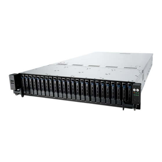
- Page 1 RS720-E9-RS24-E 2U Rackmount Server User Guide...
- Page 2 ASUSTeK COMPUTER INC. (“ASUS”). ASUS provides this manual “as is” without warranty of any kind, either express or implied, including but not limited to the implied warranties or conditions of merchantability or fitness for a particular purpose. In no...
-
Page 3: Table Of Contents
Installing an expansion card to riser card bracket 3 ....2-23 2.5.4 Installing an expansion card to riser card bracket 4 ....2-25 2.5.5 Installing an ASUS PIKE II card ..........2-27 2.5.6 Configuring an expansion card ..........2-30 2.5.7 Installing Mezzanine cards ............ - Page 4 Internal LEDs .................... 4-10 Internal connectors .................. 4-13 Chapter 5: BIOS Setup Managing and updating your BIOS ............5-2 5.1.1 ASUS CrashFree BIOS 3 utility........... 5-2 5.1.2 ASUS EZ Flash Utility ..............5-3 5.1.3 BUPDATER utility ............... 5-4 BIOS setup program .................. 5-6 5.2.1...
- Page 5 Contents 5.5.1 Trusted Computing..............5-12 5.5.2 ACPI Settings ................5-12 5.5.3 Smart Settings................5-13 5.5.4 Super IO Configuration ............. 5-13 5.5.5 Serial Port Console Redirection ..........5-14 5.5.6 Onboard LAN Configuration ............. 5-17 5.5.7 APM ..................5-18 5.5.8 PCI Subsystem Settings ............5-19 5.5.9 USB Configuration ..............
- Page 6 ..........7-8 VGA driver installation ................7-10 ® Intel Rapid Storage Technology enterprise 5.0 installation ....7-12 Appendix Z11PP-D24 block diagram ..................A-2 Notices ........................A-3 REACH ....................A-4 Australia statement notice ................A-4 ASUS contact information ..................A-5...
-
Page 7: Safety Information
Safety information Electrical Safety • Before installing or removing signal cables, ensure that the power cables for the system unit and all attached devices are unplugged. • To prevent electrical shock hazard, disconnect the power cable from the electrical outlet before relocating the system. -
Page 8: About This Guide
About this guide Audience This user guide is intended for system integrators, and experienced users with at least basic knowledge of configuring a server. Contents This guide contains the following parts: Chapter 1: Product Introduction This chapter describes the general features of the server, including sections on front panel and rear panel specifications. - Page 9 Refer to the following sources for additional information, and for product and software updates. ASUS Control Center (ACC) user guide This manual tells how to set up and use the proprietary ASUS server management utility. Visit asuscontrolcenter.asus.com for more information. ASUS websites The ASUS websites worldwide provide updated information for all ASUS hardware and software products.
-
Page 11: Chapter 1: Product Introduction
Chapter 1: Product Introduction Product Introduction This chapter describes the general features of the chassis kit. It includes sections on front panel and rear panel specifications. -
Page 12: System Package Contents
24 x Hot-swap 2.5” Storage Device Bays Component 1 x Front Panel Board 4 x Riser Cards 4 x System Fans 1 x RS720-E9-RS24-E Support CD 1 x Bag of Screws Accessories 2 x CPU Heatsink 2 x AC Power Cable... -
Page 13: System Specifications
System specifications The ASUS RS720-E9-RS24-E features the ASUS Z11PP-D24 server board. The server supports Intel Xeon Scalable Processors Family Series plus other latest technologies ® ® through the chipsets onboard. Model Name RS720-E9-RS24-E Motherboard Z11PP-D24 2 x Socket P0 (LGA 3647) - Page 14 Model Name RS720-E9-RS24-E Optional: Disk ASUS PIKE II 3108 8-port SAS HW RAID card Controller Controller 12G SAS Support Front bays: 24 x 2.5” Hot-swap Storage Device Bays I = internal (24 x SATA/SAS) A or S will Storage Bays...
- Page 15 Management Hardware Solution Software ASUS Control Center (Classic) OS Support Please find the latest OS support from http://www.asus.com/ 750 mm x 444 mm x 88 mm (2U) Dimension (Depth x Width x Height) 29.52” x 17.48” x 3.46” 1+1 Redundant...
-
Page 16: Front Panel Features
Power button VGA port • * This port is for ASUS ASMB9-iKVM only. • The Q-Code LED provides the most probable cause of an error code as a starting point for troubleshooting. The actual cause may vary from case to case. -
Page 17: Internal Features
Internal features The barebone server includes the basic components as shown. Redundant Power supply ASUS Z11PP-D24 Server Board System fans SATA/SAS back panel 24 x 2.5” storage device trays Front panel (hidden) Asset tag (hidden) The barebone server does not include a floppy disk drive. Connect a USB floppy disk drive to any of the USB ports on the front or rear panel if you need to use a floppy disk. -
Page 18: Led Information
LED information 1.7.1 Front panel LEDs Location button Power button LAN1 LED Message LED LAN2 LED Storage device LAN4 LED access LED LAN3 LED RESET button Icon Display status Description Power LED System power ON No activity Storage device access LED Blinking Read/write data into the storage device System is normal;... -
Page 19: Storage Device Status Led
Read/write data from/into the SATA/SAS storage device 1.7.3 LAN (RJ-45) LEDs ACT/LINK LED SPEED LED ACT/LINK LED SPEED LED Status Description Status Description No link 10 Mbps connection GREEN Linked ORANGE 100 Mbps connection BLINKING Data activity GREEN 1 Gbps connection ASUS RS720-E9-RS24-E... -
Page 20: Q-Code Table
1.7.4 Q-Code table Action PHASE POST CODE TYPE DESCRIPTION 0x01 Progress First post code 0x02 Progress Load BSP microcode 0x03 Progress Perform early platform Initialization SEC Start up Security Phase 0x04 Progress Set cache as ram for PEI phase 0x05 Progress Establish Stack 0x06... - Page 21 Error in checksum from wrapped Knoll/Prom keys 0x9C Error Knoll returned an invalid response to a command 0x9D Error Bootloader failed in Knoll Send Command function 0x9E Error No Knoll device found by verifying MAC (continued on the next page) ASUS RS720-E9-RS24-E 1-11...
- Page 22 Action PHASE POST CODE TYPE DESCRIPTION 0xA0 Progress Bootloader successfully entered C Main 0xA1 Progress Master initialized C2P / slave waited for master to init C2P 0xA2 Progress HMAC key successfully derived 0xA3 Progress Master got Boot Mode and sent boot mode to all slaves 0xA4 Progress SpiRom successfully initialized...
- Page 23 BIOS Setup Utility password verify 0xA9 Progress BIOS Setup Utility start 0xAB Progress BIOS Setup Utility input wait 0xAD Progress Ready to boot event 0xAE Progress Legacy boot event 0xAA Progress APIC mode Operating system phase 0xAC Progress PIC mode ASUS RS720-E9-RS24-E 1-13...
- Page 24 1-14 Chapter 1: Product Introduction...
-
Page 25: Chapter 2: Hardware Information
Chapter 2: Hardware Information Hardware Information This chapter lists the hardware setup procedures that you have to perform when installing or removing system components. -
Page 26: Chassis Cover
Chassis cover Removing the rear cover To remove the rear cover: Remove the six (6) screws on the rear cover with a Phillips screwdriver. Push and hold the cover buttons down, then slide the rear cover towards the rear to disengage it from the chassis. -
Page 27: Central Processing Unit (Cpu)
Contact your retailer immediately if the PnP cap is missing, or if you see any damage to the PnP cap/socket contacts/motherboard components. ASUS will shoulder the cost of repair only if the damage is shipment/ transit-related. - Page 28 Align the triangle mark on the CPU with the triangle mark on the CPU Carrier (A), then install the CPU into the CPU Carrier until it clicks firmly into place (B), and then install the CPU Carrier into the heatsink until it clicks firmly in place (C). CPU Carrier Ensure that the triangle mark on the CPU matches the triangle mark on the CPU Carrier.
- Page 29 Reinstall the air ducts (A), and then secure the air duct with the air duct screw removed in step 2 (B). ASUS RS720-E9-RS24-E...
-
Page 30: System Memory
System memory 2.3.1 Overview The motherboard comes with 24 Double Data Rate 4 (DDR4) Dual Inline Memory Modules (DIMM) sockets. The figure illustrates the location of the DDR4 DIMM sockets: Chapter 2: Hardware Information... -
Page 31: Memory Configurations
1 CPU Configuration (must be on CPU1) DIMM_D2 DIMM_D1 DIMM_E2 DIMM_E1 DIMM_F2 DIMM_F1 1 DIMM • 2 DIMMs 4 DIMMs • • • • • 6 DIMMs 8 DIMMs • • • • 12 DIMMs • • • • • • ASUS RS720-E9-RS24-E... - Page 32 Recommended memory configuration for 2 CPU Configuration 2 CPU Configuration DIMM_A2 DIMM_A1 DIMM_B2 DIMM_B1 DIMM_C2 DIMM_C1 2 DIMMs • 4 DIMMs • 8 DIMMs • • 12 DIMMs • • • • • • • 16 DIMMs • • • •...
- Page 33 DRAM 1 DRAM1 AD - APP DIRECT MODE MM - MEMORY MODE AD+MM - MIXED MODE DRAM1 - RDIMM, RDIMM 3DS, LRDIMM, LRDIMM 3DS DRAM2 - RDIMM only DRAM3 - RDIMM, RDIMM 3DS, LRDIMM DCPMM - DC PERSISTENT MEMORY ASUS RS720-E9-RS24-E...
- Page 34 2 CPU Configuration (symmetric population) 2 CPU Configuration (symmetric population) Modes DIMM_F2 DIMM_F1 DIMM_E2 DIMM_E1 DIMM_D2 DIMM_D1 DCPMM DRAM 1 DCPMM DRAM 1 DCPMM DRAM 1 DCPMM DRAM 1 DCPMM DRAM 1 DCPMM DRAM 1 AD+MM DCPMM DRAM 3 DCPMM DRAM 3 DCPMM DRAM 3 DRAM 1 DRAM 1 DCPMM DRAM 1 DRAM 2 DRAM 2 DCPMM...
- Page 35 DRAM1 AD - APP DIRECT MODE MM - MEMORY MODE AD+MM - MIXED MODE DRAM1 - RDIMM, RDIMM 3DS, LRDIMM, LRDIMM 3DS DRAM2 - RDIMM only DRAM3 - RDIMM, RDIMM 3DS, LRDIMM DCPMM - DC PERSISTENT MEMORY ASUS RS720-E9-RS24-E 2-11...
- Page 36 1 CPU Configuration with 1 DCPMM DIMM (asymmetric population) Asymmetric Population (2nd Socket has no DCPMM DIMM) Modes DIMM_F2 DIMM_F1 DIMM_E2 DIMM_E1 DIMM_D2 DIMM_D1 DRAM 1 DRAM 1 DRAM 1 Asymmetric Population (2nd Socket has no DCPMM DIMM) Modes DIMM_C2 DIMM_C1 DIMM_B2 DIMM_B1 DIMM_A2 DIMM_A1 DRAM 1 DRAM 1 DCPMM...
- Page 37 DRAM 1 DRAM 1 DRAM 1 2 CPU Configuration (asymmetric population) Modes DIMM_J2 DIMM_J1 DIMM_H2 DIMM_H1 DIMM_G2 DIMM_G1 DRAM 1 DRAM 1 DCPMM DRAM 1 AD - APP DIRECT MODE DRAM1 - RDIMM, RDIMM 3DS, LRDIMM, LRDIMM 3DS DCPMM - DC PERSISTENT MEMORY ASUS RS720-E9-RS24-E 2-13...
-
Page 38: Installing A Dimm On A Single Clip Dimm Socket
2.3.3 Installing a DIMM on a single clip DIMM socket Ensure to unplug the power supply before adding or removing DIMMs or other system components. Failure to do so may cause severe damage to both the motherboard and the components. Unlock a DIMM socket by pressing the DIMM notch retaining clip outward. Align a DIMM on the socket such that the notch on the DIMM matches the DIMM slot key on the socket. Unlocked retaining clip DIMM slot key A DIMM is keyed with a notch so that it fits in only one direction. DO NOT force a DIMM into a socket in the wrong direction to avoid damaging the DIMM. -
Page 39: Storage Devices
Tray lever Release the screws on each side of the metal beam drive tray to release the drive tray metal beam. The metal beam supports the drive tray horizontally to prevent the drive tray from benting or deforming. ASUS RS720-E9-RS24-E 2-15... - Page 40 Place a 2.5” hot-swap storage device into the drive tray. Ensure that the four screw holes of the storage device match the screw holes on the drive tray. screw hole Drive tray screw hole Secure the drive tray with four screws (2 screws on each side).
-
Page 41: Expansion Slot
Slot 1 Slot 2 Slot 3 x8 (ASUS PIKE II card by default) x8 (ASUS PIKE II card by default) Riser card bracket 2 Riser card bracket 2 supports PCIe Gen3 slots 4-5 top to bottom. Slot 4 can be auto-switch to x16 mode when x16 card is populated whereas slot 5 will be disabled. - Page 42 Riser card bracket 3 Riser card bracket 3 supports PCIe Gen3 slots 6-7 top to bottom. Slot 7 can be auto-switch to x16 mode when x16 card is populated whereas slot 6 will be disabled. PCIe slot Operation mode Slot 6 Slot 7 Riser card bracket 4 Riser card bracket 4 supports PCIe Gen3 slot 8.
-
Page 43: Installing An Expansion Card To Riser Card Bracket 1
Remove the screw that secures the riser card bracket 1 to the chassis. Firmly hold the riser card bracket 1, then pull it up to detach it from the PCIE1 slot on the motherboard. Riser card bracket 1 ASUS RS720-E9-RS24-E 2-19... - Page 44 Remove the screw from the metal cover (A), then remove the metal cover (B) from the riser card bracket 1. Metal cover Install the PCIE expansion card into the riser card bracket 1 (A), then secure the expansion card with the screw (B). Install the riser card bracket 1 and the PCIE expansion card assembly into the PCIE1 slot on the motherboard.
-
Page 45: Installing An Expansion Card To Riser Card Bracket 2
2, then pull it up to detach it from the PCIE3 slot on the motherboard. Remove the screw from the metal cover (A), then remove the metal cover (B) from the riser card bracket 2. Metal cover ASUS RS720-E9-RS24-E 2-21... - Page 46 Install the PCIE expansion card into the riser card bracket 2 (A), then secure the expansion card with the screw (B). Install the riser card bracket 2 and the PCIE expansion card assembly into the PCIE3 slot on the motherboard. Ensure that the golden connectors of the riser card bracket 2 is firmly seated in place.
-
Page 47: Installing An Expansion Card To Riser Card Bracket 3
Firmly hold the riser card bracket 3, then pull it up to detach it from the PCIE4 slot on the motherboard. Riser card bracket 3 Remove the screw from the metal cover (A), then remove the metal cover (B) from the riser card bracket 3. Metal cover ASUS RS720-E9-RS24-E 2-23... - Page 48 Install the PCIE expansion card into the riser card bracket 3 (A), then secure the expansion card with the screw (B). Install the riser card bracket 3 and the PCIE expansion card assembly into the PCIE4 slot on the motherboard. Ensure that the golden connectors of the riser card bracket 3 is firmly seated in place.
-
Page 49: Installing An Expansion Card To Riser Card Bracket 4
1 and 2.5.2 Installing an expansion card to riser card bracket 2. Remove the screw that secures the metal lock to the chassis. Metal lock Lift the metal lock upward. Remove the metal cover from the Metal cover chassis. ASUS RS720-E9-RS24-E 2-25... - Page 50 Install the PCIE expansion card into the riser card bracket 4. Riser card bracket 4 Move the metal lock downward to secure the riser card bracket 4 and the PCIE expansion card assembly to the chassis. Secure the metal lock to the chassis with the screw removed in step 2. Chapter 2: Hardware Information 2-26...
-
Page 51: Installing An Asus Pike Ii Card
2.5.5 Installing an ASUS PIKE II card To install an ASUS PIKE II card on the riser card bracket 2: Remove the two screws that secure the riser card bracket 2 to the chassis. Remove the screw that secures Riser card bracket 2 the riser card bracket 2 to the motherboard. - Page 52 Prepare the ASUS PIKE II card. Install the ASUS PIKE II card into the riser card bracket 2 (A), then secure it with the screw (B). Connects to ASUS Connect the mini-SAS HD cables PIKE II connector 1 to the ASUS PIKE II card.
- Page 53 Install the riser card bracket 2 and the ASUS PIKE II card assembly into the PCIE3 slot on the motherboard. Ensure that the golden connectors of the riser card bracket 2 is firmly seated in place. Secure the riser card bracket 2 to the motherboard with the screw removed in step 2.
-
Page 54: Configuring An Expansion Card
2.5.6 Configuring an expansion card After installing the expansion card, configure it by adjusting the software settings. Turn on the system and change the necessary BIOS settings, if any. See Chapter 5 for information on BIOS setup. Assign an IRQ to the card. Refer to the following tables. Install the software drivers for the expansion card. Standard Interrupt assignments Priority Standard function System Timer Keyboard Controller Programmable Interrupt Communications Port (COM2) Communications Port (COM1) Floppy Disk Controller System CMOS/Real Time Clock... -
Page 55: Installing Mezzanine Cards
Remove the screw from the metal cover (A), then remove the metal cover (B) from chassis. Select the slots that are going to be used for your Mezzanine card, then use a screwdriver and pry the corresponding slots until it pops off. ASUS RS720-E9-RS24-E 2-31... - Page 56 Prepare the Mezzanine card. Insert the ports of the Mezzanine card into the mounting hole on the chassis, then insert the golden connector of the Mezzanine card into the OCP connector on the motherboard. Ensure that the stand screws on the motherboard is aligned and matched to the screw holes of the Mezzanine card. Stand screws OCP connector Mounting hole...
- Page 57 Reinstall the metal cover (A) and secure it with the screw (B). Install the riser card bracket 1 into the PCIE connector on the motherboard. For more information, refer to section 2.5.1 Installing an expansion card to riser card bracket 1. ASUS RS720-E9-RS24-E 2-33...
-
Page 58: Installing M.2 (Ngff) Cards
2.5.8 Installing M.2 (NGFF) cards To install an M.2 (NGFF) card: Locate the M.2 (NGFF) connectors on your motherboard. Top screw Stand screw Remove the top screw and the stand from the motherboard. Select an appropriate screw hole on the motherboard for your M.2 card, then secure the stand to the motherboard. Chapter 2: Hardware Information 2-34... - Page 59 M.2 card matches the stand screw on the motherboard. Secure the M.2 card with the top screw. Ensure that the M.2 card is positioned between the top screw and the stand screw before securing it. ASUS RS720-E9-RS24-E 2-35...
-
Page 60: Cable Connections
Cable connections • The bundled system cables are pre-connected before shipment. You do not need to disconnect these cables unless you are going to remove pre-installed components to install additional devices. • Refer to Chapter 4 for detailed information on the connectors. Pre-connected system cables 8-pin BPPWR1 power connector (from power supply to backplane) Auxiliary panel 1 connector (from motherboard to front I/O board) Auxiliary panel 2 connector (from motherboard to front I/O board) System fan connectors (from motherboard FAN1-8 to system fans) Panel connector (from motherboard to front I/O board) OCU-USB to USB connector (from motherboard to front I/O board) SATA connectors (from motherboard to SATA/SAS backplane board) ISATA connectors (from motherboard to SATA/SAS backplane board) Chapter 2: Hardware Information 2-36... -
Page 61: Sata/Sas Backplane Cabling
SATA/SAS backplane cabling Backplane Connects a 8-pin plug Connects to expander board from motherboard Connects to SATA/SAS storage devices Expander board Connects to backplane Connects the data cable from the ASUS PIKE II card ASUS RS720-E9-RS24-E 2-37... -
Page 62: Removable/Optional Components
Removable/optional components This section explains how to install optional components into the system and covers the following components: System fans Redundant power supply module Ensure that the system is turned off before removing any components. You may need to remove previously installed component or factory shipped components when installing optional components. -
Page 63: Redundant Power Supply Module
PSU latch. Pull the power supply module out of the system chassis. PSU latch Module lever Insert the replacement power supply module into the chassis then push it inwards until the latch locks into place. ASUS RS720-E9-RS24-E 2-39... - Page 64 Chapter 2: Hardware Information 2-40...
-
Page 65: Chapter 3: Installation Options
Chapter 3: Installation Options Installation Options This chapter describes how to install the optional components and devices into the barebone server. -
Page 66: Tool-Less Friction Rail Kit
Tool-less Friction Rail Kit The tool less design of the rail kit allows you to easily install the rack rails into the server rack without the need for additional tools. The kit also comes with a metal stopping bracket that can be installed to provide additional support and stability to the server. -
Page 67: Installing The Tool-Less Rack Rail
Select a desired space and place the appropriate rack rail (left and right) on opposite positions on the rack. A 1U space consists of three square mounting holes with two thin lips on the top and the bottom. ASUS RS720-E9-RS24-E... - Page 68 Secure the rail components to the rail using the bundled screws. Press the spring lock (A) then insert the studs into the selected square mounting holes on the rack post. Press the spring lock on the other end of rail then insert the stud into the mounting hole on the rack post. Extend the rack rail, if necessary.
-
Page 69: Rail Kit Dimensions
Rail kit dimensions 43.6mm 900mm 43.6mm 589mm ASUS RS720-E9-RS24-E... - Page 70 Chapter 3: Installation Options...
-
Page 71: Chapter 4: Motherboard Information
Chapter 4: Motherboard Information Motherboard Information This chapter includes the motherboard layout and brief descriptions of the jumpers and internal connectors. -
Page 72: Motherboard Layout
Motherboard layout Chapter 4: Motherboard Information... - Page 73 4-23 Serial ATA connectors (7-pin SSATA1-2) 4-13 Mini-SAS HD connector (ISATA1-2) 4-13 USB 3.0 connectors (OCUUSB1) 4-24 TPM connector (14-1 pin TPM1) 4-16 Hard disk activity LED connector (4-pin HDLED1) 4-14 USB 3.0 connectors (Type A USB3_5) 4-14 ASUS RS720-E9-RS24-E...
-
Page 74: Jumpers
Jumpers Clear RTC RAM (3-pin CLRTC1) This jumper allows you to clear the Real Time Clock (RTC) RAM in CMOS. You can clear the CMOS memory of date, time, and system setup parameters by erasing the CMOS RTC RAM data. The onboard button cell battery powers the RAM data in CMOS, which include system setup information such as system passwords. - Page 75 1–2 to activate the VGA feature. LAN controller setting (3-pin LAN_SW1, LAN_SW2) ® These jumpers allow you to enable or disable the onboard Intel I350-AM2 Gigabit LAN1/2 controller. Set to pins 1–2 to activate the Gigabit LAN feature. ASUS RS720-E9-RS24-E...
- Page 76 ME firmware force recovery setting (3-pin ME_RCVR1) This jumper allows you to quickly recover the Intel Management Engine (ME) firmware when it becomes corrupted. Baseboard Management Controller setting (3-pin BMC_EN1) This jumper allows you to enable (default) or disable on-board BMC. Ensure to set this BMC jumper to enabled to avoid system fan control and hardware monitor error.
- Page 77 DDR4 thermal event setting (3-pin DIMMTRIP1, DIMMTRIP2) This jumper allows you to enable or disable DDR4 DIMM thermal sensing event pin. PCH_MFG1 setting (3-pin PCH_MFG1) This jumper allows you to update the BIOS ME block. ASUS RS720-E9-RS24-E...
- Page 78 Smart Ride Through (SmaRT) setting (3-pin SMART_PSU1) This jumper allows you to enable or disable the Smart Ride Through (SmaRT) function. This feature is enabled by default. Set to pins 2-3 to disable it. When enabled, SmaRT allows uninterrupted operation of the system during an AC loss event. DMLAN setting (3-pin DM_IP_SEL1) This jumper allows you to select the DMLAN setting.
- Page 79 LANNCSI setting (3-pin LANNCSI_SEL1) This jumper allows you to select which LAN NCSI to function. IPMI SW setting (3-pin IPMI_SW1) This jumper allows you to select which protocol in the GPU sensor to function. ASUS RS720-E9-RS24-E...
-
Page 80: Internal Leds
Internal LEDs Standby Power LED (SBPWR1) The motherboard comes with a standby power LED. The green LED lights up to indicate that the system is ON, in sleep mode, or in soft-off mode. This is a reminder that you should shut down the system and unplug the power cable before removing or plugging in any motherboard component. - Page 81 The read or write activities of any device connected to the onboard SATA, or SATA/SAS add-on card causes the rear panel LED to light up. Message LED (MESLED1) This onboard LED lights up to red when there is a BMC event log is generated. ASUS RS720-E9-RS24-E 4-11...
- Page 82 BMC LED (BMCLED1) The BMC LED lights up to indicate that the on-board BMC is functional. CATT LED (CATTERR1) The CATT LED indicates that the system has experienced a fatal or catastrophic error and cannot continue to operate. 4-12 Chapter 4: Motherboard Information...
-
Page 83: Internal Connectors
If the SATA M.2 (NGFF1) slot is occupied, the SSATA2 slot will be disabled. Mini-SAS HD connector (ISATA1-2) This motherboard comes with mini Serial Attached SCSI (SAS) HD connectors, the storage technology that supports Serial ATA. Each connector supports up to four devices. ASUS RS720-E9-RS24-E 4-13... - Page 84 USB 3.0 connectors (Type A USB3_5) The USB3_5 connector is for Type-A USB 3.0 devices. You can enjoy all the benefits of USB 3.0 including faster data transfer speeds of up to 5 Gbps, faster charging time for USB-chargeable devices, optimized power efficiency, and backward compatibility with USB 2.0.
- Page 85 These connectors are for the power supply plugs that connects to additional fans. The power supply plugs are designed to fit these connectors in only one orientation. Find the proper orientation and push down firmly until the connectors completely fit. ASUS RS720-E9-RS24-E 4-15...
- Page 86 System fan connectors (4-pin FAN1-8) The fan connectors support cooling fans of 0.8A–1.0A (12 W max.) or a total of 6.4 A–8.0 A (96 W max.) at +12V. Connect the fan cables to the fan connectors on the motherboard, making sure that the black wire of each cable matches the ground pin of the connector.
- Page 87 Pressing the power switch for more than four seconds while the system is ON turns the system OFF. Reset button (2-pin RESET) This 2-pin connector is for the chassis-mounted reset button for system reboot without turning off the system power. ASUS RS720-E9-RS24-E 4-17...
- Page 88 Auxiliary panel connector (20-2 pin AUX_PANEL1, 20-pin AUX_PANEL2) This connector is for additional front panel features including front panel SMB, locator LED and switch, chassis intrusion, and LAN LEDs. Front panel SMB (6-1 pin FPSMB) These leads connect the front panel SMBus cable. LAN activity LED (2-pin LAN1_LED, LAN2_LED) These leads are for the Gigabit LAN activity LEDs on the front panel.
- Page 89 Find the proper orientation and push down firmly until the connectors completely fit. DO NOT connect the back panel to these connectors. Doing so may cause system boot errors and permanent damage to your motherboard or device. ASUS RS720-E9-RS24-E 4-19...
- Page 90 VGA connector (16-pin VGA_HDR1) This connector supports the VGA High Dynamic-Range interface. Chassis Intrusion (2-pin INTRUSION1) These leads are for the intrusion detection feature for chassis with intrusion sensor or microswitch. When you remove any chassis component, the sensor triggers and sends a high level signal to these leads to record a chassis intrusion event.
- Page 91 This connector supports type 2242 / 2260 / 2280 / 22110 devices on both PCI-E and SATA interface. • If the SATA M.2 (NGFF1) slot is occupied, the SSATA2 slot will be disabled. The M.2 (NGFF) device is purchased separately ASUS RS720-E9-RS24-E 4-21...
- Page 92 Serial port connector (10-1 pin COM1) This connector is for a serial (COM) port. Connect the serial port module cable to this connector, then install the module to a slot opening at the back of the system chassis. The COM module is purchased separately. Micro SD card slot (MSD1) Your motherboard supports SD Memory Card v2.00 (SDHC) / v3.00 (SDXC).
- Page 93 This connector allows you to connect a KEY module to support Intel VMD RAID function. Serial General Purpose Input/Output connector (6-1 pin SSGPIO1) The SSGPIO 1 connector is used for the Intel Rapid Storage Technology Enterprise SGPIO interface that controls the LED pattern generation, device information, and general purpose data. ASUS RS720-E9-RS24-E 4-23...
- Page 94 OCP LAN Activity LED connector (4-1 pin OCP_LED1) OCP LAN LED connector supports OCP LAN card Active LED. USB 3.0 connectors (OCUUSB1) Connect a compatible USB module cable to the OCUUSB1 connector, and then install the module to a slot opening at the back or front of the system chassis. You can enjoy all the benefits of USB 3.0 including faster data transfer speeds of up to 5 Gbps, faster charging time for USB-chargeable devices, optimized power efficiency, and backward compatibility with USB 2.0.
- Page 95 VPP_I2C1 connector (10-1 pin VPP_I2C1) This connector is used for the Intel VMD function and sensor readings. ASUS RS720-E9-RS24-E 4-25...
- Page 96 4-26 Chapter 4: Motherboard Information...
-
Page 97: Chapter 5: Bios Setup
Chapter 5: BIOS Setup BIOS Setup This chapter tells how to change the system settings through the BIOS Setup menus. Detailed descriptions of the BIOS parameters are also provided. -
Page 98: Managing And Updating Your Bios
BIOS in the future. Copy the original motherboard BIOS using the BUPDATER utility. 5.1.1 ASUS CrashFree BIOS 3 utility The ASUS CrashFree BIOS 3 is an auto recovery tool that allows you to restore the BIOS file when it fails or gets corrupted during the updating process. You can update a corrupted BIOS file using a USB flash drive that contains the updated BIOS file. -
Page 99: Asus Ez Flash Utility
5.1.2 ASUS EZ Flash Utility The ASUS EZ Flash Utility feature allows you to update the BIOS without having to use a DOS-based utility. Before you start using this utility, download the latest BIOS from the ASUS website at www.asus.com. To update the BIOS using EZ Flash Utility: Insert the USB flash disk that contains the latest BIOS file into the USB port. Enter the BIOS setup program. Go to the Tool menu then select ASUS EZ Flash Utility. -
Page 100: Bupdater Utility
The BUPDATER utility allows you to update the BIOS file in the DOS environment using a bootable USB flash disk drive with the updated BIOS file. Updating the BIOS file To update the BIOS file using the BUPDATER utility: Visit the ASUS website at www.asus.com and download the latest BIOS file for the motherboard. Save the BIOS file to a bootable USB flash disk drive. Copy the BUPDATER utility (BUPDATER.exe) from the ASUS support website at www.asus.com/support to the bootable USB flash disk drive you created earlier. Boot the system in DOS mode, then at the prompt, type: BUPDATER /i[filename].CAP where [filename] is the latest or the original BIOS file on the bootable USB flash disk drive, then press <Enter>. A:\>BUPDATER /i[file name].CAP Chapter 5: BIOS Setup... - Page 101 The utility verifies the file, then starts updating the BIOS file. ASUS Tek. EzFlash Utility Current Platform New Platform Platform : Z11PP-D24 Platform : Z11PP-D24 Version : 0215 Version : 0217 Build date: 01/13/2017 Build date: 02/20/2017 Start Programming Flash. DO NOT SHUTDOWN THE SYSTEM!!! Write DO NOT shut down or reset the system while updating the BIOS to prevent system boot failure! The utility returns to the DOS prompt after the BIOS update process is completed.
-
Page 102: Bios Setup Program
If the system becomes unstable after changing any BIOS settings, load the default settings to ensure system compatibility and stability. Press <F5> and select Yes to load the BIOS default settings. • The BIOS setup screens shown in this section are for reference purposes only, and may not exactly match what you see on your screen. • Visit the ASUS website (www.asus.com) to download the latest BIOS file for this motherboard. Chapter 5: BIOS Setup... -
Page 103: Bios Menu Screen
Event Logs For changing the event log settings Server Mgmt For changing the Server Mgmt settings For changing the security settings Security Boot For changing the system boot configuration Tool For configuring options for special functions For selecting the exit options Save & Exit To select an item on the menu bar, press the right or left arrow key on the keyboard until the desired item is highlighted. ASUS RS720-E9-RS24-E... -
Page 104: Menu Items
5.2.3 Menu items The highlighted item on the menu bar displays the specific items for that menu. For example, selecting Main shows the Main menu items. The other items (such as Advanced) on the menu bar have their respective menu items. 5.2.4 Submenu items A solid triangle before each item on any menu screen means that the item has a submenu. To display the submenu, select the item then press <Enter>. -
Page 105: Main Menu
Main menu When you enter the BIOS Setup program, the Main menu screen appears. The Main menu provides you an overview of the basic system information, and allows you to set the system date, time, language, and security settings. 5.3.1 System Date [Day xx/xx/xxxx] Allows you to set the system date. 5.3.2 System Time [xx:xx:xx] Allows you to set the system time. ASUS RS720-E9-RS24-E... -
Page 106: Performance Tuning Menu
Performance Tuning menu The Performance Tuning menu items allow you to change performance related settings for different scenarios. Optimized Performance Setting [Default] Allows you to select performance settings for different scenarios. [Default] Default settings. [By Benchmark] O ptimize for different kinds of benchmarks. Select this option, then select a benchmark type from the >> list. [By Workload] O ptimize for different kinds of workloads. Select this option, then select a workload type from the >>... -
Page 107: Advanced Menu
Advanced menu The Advanced menu items allow you to change the settings for the CPU and other system devices. Take caution when changing the settings of the Advanced menu items. Incorrect field values can cause the system to malfunction. ASUS RS720-E9-RS24-E 5-11... -
Page 108: Trusted Computing
5.5.1 Trusted Computing Configuration Security Device Support [Disabled] Allows you to enable or disable the BIOS support for security device. Configuration options: [Disabled] [Enabled] 5.5.2 ACPI Settings Enable ACPI Auto Configuration [Disabled] Allows you to enable or disable the BIOS ACPI Auto Configuration. Configuration options: [Disabled] [Enabled] Enable Hibernation [Enabled] Allows you to enable or disable the ability of the system to hibernate (OS/Sleep State). Configuration options: [Disabled] [Enabled] This option may be not effective with some OS. -
Page 109: Smart Settings
Allows you to enable or disable Serial Port. Configuration options: [Disabled] [Enabled] The following item appears only when you set Serial Port to [Enabled]. Change Settings [Auto] Allows you to choose the setting for Super IO device. Configuration options: [ Auto] [IO=3F8h; IRQ=4;] [IO=3F8h; IRQ=3, 4, 5, 6, 7, 9, 10, 11, 12;] [IO=2F8h; IRQ=3, 4, 5, 6, 7, 9, 10, 11, 12;] [IO=3E8h; IRQ=3, 4, 5, 6, 7, 9, 10, 11, 12;] [IO=2E8h; IRQ=3, 4, 5, 6, 7, 9, 10, 11, 12;] ASUS RS720-E9-RS24-E 5-13... -
Page 110: Serial Port Console Redirection
5.5.5 Serial Port Console Redirection COM1/COM2 Console Redirection [Disabled] Allows you to enable or disable the console redirection feature. Configuration options: [Disabled] [Enabled] The following item appears only when you set Console Redirection to [Enabled]. Console Redirection Settings These items become configurable only when you enable the Console Redirection item. The settings specify how the host computer and the remote computer (which the user is using) will exchange data. - Page 111 Configuration options: [80x24] [80x25] Putty Keypad [VT100] This allows you to select the FunctionKey and Keypad on Putty. Configuration options: [VT100] [LINUX] [XTERMR6] [SCO] [ESCN] [VT400] Redirection After BIOS POST [Always Enable] This setting allows you to specify if Bootloader is selected than Legacy console redirection. Configuration options: [Always Enable] [Bootloader] Legacy Console Redirection Settings Legacy Console Redirection Port [COM1] Allows you to select a COM port to display redirection of Legacy OS and Legacy OPROM Messages. Configuration options: [COM1] [COM2] ASUS RS720-E9-RS24-E 5-15...
- Page 112 Serial Port for Out-of-Band Management/Windows Emergency Management Services (EMS) Console Redirection [Disabled] Allows you to enable or disable the console redirection feature. Configuration options: [Disabled] [Enabled] The following item appears only when you set Console Redirection to [Enabled]. Console Redirection Settings Out-of-Band Mgmt Port [COM1] Microsoft Windows Emergency Management Services (EMS) allow for remote management of a Windows Server OS through a serial port.
-
Page 113: Onboard Lan Configuration
The following items appear only when Intel LAN1 Enable is set to [Enabled]. Intel LAN 1 ROM Type [PXE] Allows you to select the Intel LAN ROM type. Configuration options: [PXE] [iSCSI] [Disabled] Intel LAN2 Enable [Enabled] Allows you to enable or disable the Intel LAN. Configuration options: [Disabled] [Enabled] The following items appear only when Intel LAN2 Enable is set to [Enabled]. Intel LAN 2 ROM Type [Disabled] Allows you to select the Intel LAN ROM type. Configuration options: [PXE] [iSCSI] [Disabled] ASUS RS720-E9-RS24-E 5-17... -
Page 114: Apm
5.5.7 Allows you to configure the Advance Power Management (APM) settings. Restore AC Power Loss [Last State] When set to [Power Off], the system goes into off state after an AC power loss. When set to [Power On], the system will reboot after an AC power loss. When set to [Last State], the system goes into either off or on state, whatever the system state was before the AC power loss. Configuration options: [Power Off] [Power On] [Last State] Power On By PCIE [Disabled] [Disabled] Disables the PCIE devices to generate a wake event. [Enabled] Enables the PCIE devices to generate a wake event. Power On By RTC [Disabled] [Disabled] Disables RTC to generate a wake event. [Enabled] W hen set to [Enabled], the items RTC Alarm Date (Days) and Hour/Minute/Second will become user-configurable with set values. 5-18 Chapter 5: BIOS Setup... -
Page 115: Pci Subsystem Settings
PCIE Express Settings PCI Express Device Register Settings Relaxed Ordering [Enabled] Enables or disables PCI Express device relaxed ordering. Configuration options: [Disabled] [Enabled] Extended Tag [Disabled] If Enable allows device is use 8-bit tag field as a requester. Configuration options: [Disabled] [Enabled] No Snoop [Enabled] Enables or disables PCI Express device No snoop option. Configuration options: [Disabled] [Enabled] ASUS RS720-E9-RS24-E 5-19... - Page 116 PCI Express Link Register Settings ASPM Support [Disabled] Allows to set the ASPM level. Configuration options: [Disabled] [Auot] [Force L0s] [Force L0s] Force all links to L0s state. [Auto] BIOS auto configure. [Disabled] Disabled ASPM. Unpopulated Links [Keep Link ON] In order to save power, software will disable unpopulated PCI Express links, if this option set to Disabled. Configuration options: [Keep Link ON] [Disabled] PCIE OPROM Slot Options PCIE1-3 Slot OPROM [Enabled] This option allows you to enable or disable the OPROM of the PCIe slots. Configuration options: [Disabled] [Enabled] MEZZ1 Slot OPROM [Enabled] This option allows you to enable or disable the OPROM of the MEZZ slot.
-
Page 117: Usb Configuration
USB Mass Storage Driver Support [Enabled] Allows you to enable or disable the USB Mass Storage driver support. Configuration options: [Disabled] [Enabled] Mass Storage Devices AMI Virtual CDROM0-2 / Floppy / HDisk0 1.00 [Auto] Allows you to select the mass storage device emulation type. Configuration options: [Auto] [Floppy] [Forced FDD] [Hard Disk] [CD-ROM] ASUS RS720-E9-RS24-E 5-21... -
Page 118: Csm Configuration
5.5.10 CSM Configuration CSM Support [Enabled] This option allows you to enable or disable CSM Support. Configuration options: [Disabled] [Enabled] The following item appears only when CSM Support is set to [Enabled]. GateA20 Active [Upon Request] This allows you to set the GA20 option. Configuration options: [Upon Request] [Always] Option ROM Messages [Force BIOS] This allows you to set the display mode for option ROM. -
Page 119: Nvme Configuration
5.5.11 NVMe Configuration This page will display the NVMe controller and drive information. 5.5.12 Offboard SATA Controller Configuration This page will display the offboard SATA controller and drive information. ASUS RS720-E9-RS24-E 5-23... -
Page 120: Network Stack Configuration
5.5.13 Network Stack Configuration Network stack [Disabled] Enables or disables the network stack feature. Configuration options: [Disable] [Enable] The following item appears only when Network stack is set to [Enabled]. Ipv4 PXE Support [Disabled] Enables or disables the Ipv4 PXE Boot Support. If disabled, Ipv4 PXE boot option will not be created. Configuration options: [Disabled] [Enabled] Ipv4 HTTP Support [Disabled] Enables or disables the Ipv4 HTTP Boot Support. If disabled, Ipv4 HTTP boot option will not be created. Configuration options: [Disabled] [Enabled] Ipv6 PXE Support [Disabled] Enables or disables the Ipv6 PXE Boot Support. If disabled, Ipv6 PXE boot option will not be created. -
Page 121: Iscsi Configuration
5.5.14 iSCSI Configuration Allows you to configure the iSCSi parameters. Platform Configuration menu The IntelRCSetup menu items allow you to change the platform settings. ASUS RS720-E9-RS24-E 5-25... -
Page 122: Pch Configuration
5.6.1 PCH Configuration PCH Devices DeepSx Power Policies [Disabled] Allows you to configure the DeepSx Mode configuration. Configuration options: [Disabled] [Enabled in S5] [Enabled in S4 and S5] GP27 Wake From DeepSx [Disabled] Allows you to enable or disable GP27 Wake From DeepSx. Configuration options: [Disabled] [Enabled] PCI Express Configuration PCI-E ASPM Support (Global) [L1 Only] Allows you to select ASPM support for all downstream devices. Configuration options: [Per individual port] [L1 Only] PCH DMI ASPM [Platform-POR] Allows you to configure the PCH DMI ASPM. - Page 123 Allows you to enable or disable USB 3.0 pins or on a per pin basis. Configuration options: [Select Per-Pin] [Disable all pins] [Enable all pins] USB Per-Connector Disable [Disabled] Allows you to enable or disable each of the USB physical connectors. Once a connector is disabled, any USB devices plugged into the connector will not be detected by BIOS or OS. Configuration options: [Disabled] [Enabled] ASUS RS720-E9-RS24-E 5-27...
-
Page 124: Miscellaneous Configuration
The following items appears only when the USB Per-Connector Disable is set to [Enabled]. USB_1-8 [Enabled] Configuration options: [Disabled] [Enabled] USB3_1-5 [Enabled] Configuration options: [Disabled] [Enabled] Security Configuration SMM BIOS Write Protect [Enabled] Allows you to enable or disable SMM BIOS Write Protect. Configuration options: [Disabled] [Enabled] 5.6.2 Miscellaneous Configuration Active Video [Offboard Device] Allows you to select the video type. Configuration options: [Auto] [Onboard Device] [Offboard Device] 5.6.3 Server ME Configuration... -
Page 125: Runtime Error Logging Support
5.6.4 Runtime Error Logging Support Runtime Error Logging System Errors [Enabled] This item allows you to enable or disable System Errors. Configuration options: [Disabled] [Enabled] Whea Settings Whea Support [Disabled] This item allows you to enable or disable the WHEA support. Configuration options: [Disabled] [Enabled] Socket Configuration menu The IntelRCSetup menu items allow you to change the socket settings. ASUS RS720-E9-RS24-E 5-29... -
Page 126: Processor Configuration
5.7.1 Processor Configuration Hyper Threading [ALL] [Enabled] Allows you to enable or disable the Hyper-Threading Technology function. When disabled, only one thread per activated core is enabled. Configuration options: [Disabled] [Enabled] Enable Intel(R) TXT Support [Disabled] Forces the XD feature log to always return 0 when disabled. Configuration options: [Disabled] [Enabled] VMX [Enabled] Enables the Vanderpool Technology. Takes effect after reboot. Configuration options: [Disabled] [Enabled] Enable SMX [Disabled] Enables the Safer Mode Extensions. Configuration options: [Disabled] [Enabled] Hardware Prefetcher [Enabled] This Item allows you to turn on/off the mid level cache(L2) streamer prefetcher. -
Page 127: Common Refcode Configuration
This item allows you to select the MMIO High Base. Configuration options: [56T] [40T] [24T] [16T] [4T] [1T] MMIO High Granularity Size [256G] This item allows you to select the allocation size used to assign MMIOH resources. Configuration options: [1G] [4G] [16G] [64G] [256G] [1024G] Numa [Enabled] This item enables or disables the Non uniform Memory Access (NUMA). Configuration options: [Disabled] [Enabled] ASUS RS720-E9-RS24-E 5-31... -
Page 128: Upi Configuration
5.7.3 UPI Configuration UPI General Configuration UPI Status This item displays information about the UPI status. Link Speed Mode [Fast] This item allows you to select the UPI link speed as either the fast mode or slow mode. Configuration options: [Slow] [Fast] Link Frequency Select [Auto] This item allows for selecting the UPI link frequency. Configuration options: [Auto] [9.6 GB/s] [10.4 GB/s] [Use Per Link Setting] UPI Link0p Enable [Enabled] Configuration options: [Disabled] [Enabled] [Auto] UPI Link1 Enable [Enabled] Configuration options: [Disabled] [Enabled] [Auto] Directory Mode Enable [Enabled] Configuration options: [Disabled] [Enabled] SNC [Disabled] Configuration options: [Disabled] [Enabled] [Auto]... -
Page 129: Memory Configuration
Displays memory topology with DIMM population information. Page Policy Allows you to configure Page Policy settings. Page Policy [Disabled] Configuration options: [Auto] [Closed] [Adaptive] Memory Map IMC Interleaving [Auto] Select different IMC interleaving setting. Configuration options: [ Auto] [1-way Interleave] [2-way Interleave] Channel Interleaving [Auto] Select different channel interleaving setting. Configuration options: [ Auto] [1-way Interleave] [2-way Interleave] [3-way Interleave] ASUS RS720-E9-RS24-E 5-33... - Page 130 Rank Interleaving [Auto] Select different rank interleaving setting. Configuration options: [ Auto] [1-way Interleave] [2-way Interleave] [4-way Interleave] [8-way Interleave] Memory RAS Configuration Mirror Mode [Disabled] Allows you to select Mirror Modes. Mirror Mode will set entire 1LM/2LM memory in system to be mirrored, consequently reducing the memory capacity by half. Enabling Mirror Mode will disable XPT Prefetch. Configuration options: [Disabled] [Mirror Mode 1LM] [Mirror Mode 2LM] UEFI ARM Mirror [Disabled] Allows you to enable or disable UEFI ARM Mirror. Configuration options: [Disabled] [Enabled] Memory Rank Sparing [Disabled] Allows you to enable or disable Memory Rank Sparing Configuration options: [Disabled] [Enabled] Patrol Scrub [Enabled] Allows you to enable or disable Patrol Scrub.
-
Page 131: Iio Configuration
Configuration options: [Disabled] [Enabled] PCI Express Global Options PCI-E ASPM Support (Global) [Per-Port] Allows you to enable or disable ASPM support for all downstream devices. Configuration options: [Disabled] [Per-Port] [L1 Only] PCIE relaxed Ordering [Enabled] Allows you to enable or disable PCIE relaxed Ordering. Configuration options: [Disabled] [Enabled] ASUS RS720-E9-RS24-E 5-35... -
Page 132: Advanced Power Management Configuration
5.7.6 Advanced Power Management Configuration CPU P State Control Boot performance mode [Max Performance] Allows you to switch between Boot performance mode. Configuration options: [Max Performance] [Max Efficient] [Set by Intel Node Manager] Energy Efficient Turbo [Enabled] Allows you to enable or disable Energy Efficient Turbo. Configuration options: [Disabled] [Enabled] Turbo Mode [Enabled] Allows you to enable or disable Turbo Mode. Configuration options: [Disabled] [Enabled] Hardware PM State Control Hardware P-States [Native Mode]... - Page 133 This option is used to control the effective window of the average C0 an P0 time. Configuration options: [0] - [FF] P0 TotalTimeThreshold Low [23] The HW switching mechanism DISABLES the performance setting (0) when the total P0 time is less than the threshold set. Configuration options: [0] - [3F] P0 TotalTimeThreshold High [3a] The HW switching mechanism Enables the performance setting (0) when the total P0 time is greater than the threshold set. Configuration options: [0] - [3F] ASUS RS720-E9-RS24-E 5-37...
-
Page 134: Event Logs Menu
Event Logs menu The Event Logs menu items allow you to change the event log settings and view the system event logs. 5.8.1 Change Smbios Event Log Settings Press <Enter> to change the Smbios Event Log configuration. All values changed here do not take effect until computer is restarted. Enabling/Disabling Options Smbios Event Log [Enabled] Change this to enable or disable all features of Smbios Event Logging during boot. Configuration options: [Disabled] [Enabled] Erasing Settings Erase Event Log [No] Choose options for erasing Smbios Event Log. Erasing is done prior to any logging activation during reset. Configuration options: [No] [Yes, Next reset] [Yes, Every reset] 5.8.2 View Smbios Event Log Press <Enter> to view all smbios event logs. 5-38 Chapter 5: BIOS Setup... -
Page 135: Server Mgmt Menu
Configuration options: [Do Nothing] [Reset] [Power Down] System Event Log Allows you to change the SEL event log configuration. Erase SEL [No] Allows you to choose options for erasing SEL. Configuration options: [No] [Yes, On next reset] [Yes, On every reset] When SEL is Full [Do Nothing] Allows you to choose options for reactions to a full SEL. Configuration options: [Do Nothing] [Erase Immediately] BMC network configuration The sub-items in this configuration allow you to configure the BMC network parameters. View System Event Log This item allows you to view the system event log records. ASUS RS720-E9-RS24-E 5-39... -
Page 136: Security Menu
5.10 Security menu This menu allows a new password to be created or a current password to be changed. The menu also enables or disables the Secure Boot state and lets the user configure the System Mode state. Administrator Password To set an administrator password: Select the Administrator Password item and press <Enter>. From the Create New Password box, key in a password, then press <Enter>. Confirm the password when prompted. To change an administrator password: Select the Administrator Password item and press <Enter>. - Page 137 To clear a user password: Select the Clear User Password item and press <Enter>. Select Yes from the Warning message window then press <Enter>. Secure Boot This item allows you to customize the Secure Boot settings. Secure Boot Allows you to enable or disable Secure Boot. Configuration options: [Disabled] [Enabled] ASUS RS720-E9-RS24-E 5-41...
-
Page 138: Boot Menu
These items specify the boot device priority sequence from the available devices. The number of device items that appears on the screen depends on the number of devices installed in the system. • To select the boot device during system startup, press <F8> when ASUS Logo appears. • To access Windows OS in Safe Mode, please press <F8> after POST. Hard Drive / CD/DVD ROM Drive / Network Device BBS Priorities These items appear allow you to set the order of the legacy devices in this group. -
Page 139: Tool Menu
IPMI Hardware Monitor Allows you to run the IPMI hardware monitor. Start EZ Flash Allows you to run ASUS EZ Flash BIOS ROM Utility when you press <Enter>. Refer to the ASUS EZ Flash Utility section for details. 5.13 Save & Exit menu The Save &... - Page 140 5-44 Chapter 5: BIOS Setup...
-
Page 141: Chapter 6: Raid Configuration
Chapter 6: RAID Configuration RAID Configuration This chapter provides instructions for setting up, creating, and configuring RAID sets using the available utilities. -
Page 142: Setting Up Raid
Setting up RAID ® The motherboard supports the Intel Rapid Storage Technology enterprise Option ROM Utility with RAID 0, RAID 1, RAID 10, and RAID 5 support (for Windows OS and Linux). 6.1.1 RAID definitions RAID 0 (Data striping) optimizes two identical hard disk drives to read and write data in parallel, interleaved stacks. -
Page 143: Installing Hard Disk Drives
Rapid Storage Technology ® if you installed Serial ATA hard disk drives on the Serial ATA connectors supported by the Intel C621 chipset. ® Refer to the succeeding section for details on how to use the RAID configuration utility. ASUS RS720-E9-RS24-E... -
Page 144: Intel ® Rapid Storage Technology Enterprise
® Intel Rapid Storage Technology enterprise SATA/SSATA Option ROM Utility ® The Intel Rapid Storage Technology enterprise SATA/SSATA Option ROM utility allows you to create RAID 0, RAID 1, RAID 10 (RAID 1+0), and RAID 5 set from Serial ATA hard disk drives that are connected to the Serial ATA connectors supported by the Southbridge. -
Page 145: Creating A Raid Set
]-Prev/Next [TAB]-(M)aster [SPACE]-(R)ecovery [ENTER]-Done Use the up/down arrow keys to move the selection bar then press <Space> to select a disk. A small triangle before the Port number marks the selected drive. Press <Enter> when you are done. ASUS RS720-E9-RS24-E... - Page 146 Use the up/down arrow keys to select the stripe size for the RAID array (for RAID 0, 10 and 5 only) then press <Enter>. The available stripe size values range from 4 KB to 128 KB. The following are typical values: RAID 0: 128KB RAID 10: 64KB RAID 5: 64KB...
-
Page 147: Deleting A Raid Set
<N> to return to the DELETE VOLUME menu. DELETE VOLUME VERIFICATION ALL DATA IN THE VOLUME WILL BE LOST! (This does not apply to Recovery volumes) Are you sure you want to delete volume “Volume0”? (Y/N): ASUS RS720-E9-RS24-E... -
Page 148: Resetting Disks To Non-Raid
6.2.3 Resetting disks to Non-RAID Take caution before you reset a RAID volume hard disk drive to non-RAID. Resetting a RAID volume hard disk drive deletes all internal RAID structure on the drive. To reset a RAID set: From the utility main menu, select 3. Reset Disks to Non-RAID and press <Enter>. Press the up/down arrow keys to select the drive(s) or disks of the RAID set you want to reset, then press <Space>. -
Page 149: Exiting The Intel ® Rapid Storage Technology Enterprise
Rebuild completes in the operating system. Select the port of destination disk for rebuilding (ESC to exit): Port Drive Model Serial # Size XXXXXXXXXXX XXXXXXXX XXX.GB ]-Previous/Next [ENTER]-Select [ESC]-Exit Select a destination disk with the same size as the original hard disk. ASUS RS720-E9-RS24-E... - Page 150 The utility immediately starts rebuilding after the disk is selected. When done, the status of the degraded RAID volume is changed to “Rebuild”. Intel(R) Rapid Storage Technology enterprise - SATA Option ROM - 3.6.0.1023 Copyright(C) 2003-12 Intel Corporation. All Rights Reserved. MAIN MENU 1.
-
Page 151: Setting The Boot Array In The Bios Setup Utility
Use up/down arrow keys to select the boot priority and press <Enter>. See the Boot menu section of Chapter 5 for more details. From the Exit menu, select Save Changes & Exit, then press <Enter>. When the confirmation window appears, select Yes, then press <Enter>. ASUS RS720-E9-RS24-E 6-11... -
Page 152: Intel ® Rapid Storage Technology Enterprise (Windows)
® Intel Rapid Storage Technology enterprise (Windows) The Intel Rapid Storage Technology enterprise allows you to create RAID 0, RAID 1, RAID ® 10 (RAID 1+0), and RAID 5 set(s) from Serial ATA hard disk drives that are connected to the Serial ATA connectors supported by the Southbridge. -
Page 153: Creating A Raid Set
Select Volume Size tab, you can drag the bar to decide the volume size. Click Next. • If you do not want to keep the data on one of the selected disks, select NO when prompted. • If you want to Enable volume write-back cache or Initialize volume, click Advanced. ASUS RS720-E9-RS24-E 6-13... - Page 154 Confirm the volume creation, than click Create Volume to continue. This process could take a while depending on the number and size of the disks. You can continue using other applications during this time. Wait until the process is completed, then click OK when prompted. You still need to partition your new volume using Windows Disk Management before adding any data.
-
Page 155: Changing A Volume Type
OK. The available stripe size values range from 4 KB to 128 KB. The following are typical values: RAID 0: 128KB RAID 10: 64KB RAID 5: 64KB We recommend a lower stripe size for server systems, and a higher stripe size for multimedia computer systems used mainly for audio and video editing. ASUS RS720-E9-RS24-E 6-15... -
Page 156: Deleting A Volume
6.3.3 Deleting a volume Be cautious when deleting a volume. You will lose all data on the hard disk drives. Before you proceed, ensure that you back up all your important data from your hard drives. To delete a volume: From the utility main menu, select the volume (ex. -
Page 157: Preferences
Allow you to set to show the notification area icon and show system information, warning, or errors here. E-Mail Preferences Allow you to set to sent e-mail of the following events: • Storage system information • Storage system warnings • Storage system errors ASUS RS720-E9-RS24-E 6-17... - Page 158 6-18 Chapter 6: RAID Configuration...
-
Page 159: Chapter 7: Driver Installation
Chapter 7: Driver Installation Driver Installation This chapter provides the instructions for installing the necessary drivers for different system components in the ® Windows Operating Systems. -
Page 160: Raid Driver Installation
RAID driver installation After creating the RAID sets for your server system, you are now ready to install an operating system to the independent hard disk drive or bootable array. This part provides the instructions on how to install the RAID controller drivers during OS installation. 7.1.1 Creating a USB flash drive with RAID drive When installing Windows®... - Page 161 Click Browse to continue. Locate the driver in the corresponding folder of the Support DVD or USB flash drive and then click OK to continue. Select the RAID controller driver you need from the list and click Next. ASUS RS720-E9-RS24-E...
- Page 162 When the system finishes loading the RAID driver, Replace the motherboard Support DVD with the Windows Server installation disc. • Remove the USB flash drive. • Select the drive to install Windows and click Next. Setup then proceeds with the OS installation. Follow screen instructions to continue. Chapter 7: Driver Installation...
-
Page 163: Management Applications And Utilities Installation
The contents of the support DVD are subject to change at any time without notice. Visit the ASUS website (www.asus.com) for the latest updates on software and utilities. - Page 164 7.3.1 Drivers menu tab The Drivers Menu shows the available device drivers if the system detects installed devices. Install the necessary drivers to activate the devices. 7.3.2 Utilities menu tab The Utilities menu displays the software applications and utilities that the motherboard supports.
- Page 165 You need an internet browser installed in your OS to view the User Guide. 7.3.4 Contact information menu The Contact menu displays the ASUS contact information, e-mail addresses, and useful links if you need more information or technical support for your motherboard. ASUS RS720-E9-RS24-E...
-
Page 166: Intel ® Chipset Device Software Installation
Intel chipset device software installation ® This section provides the instructions on how to install the Intel chipset device software on ® the system. You need to manually install the Intel chipset device software on a Windows operating ® system. To install the Intel chipset device software: ®... - Page 167 Read the License Agreement and click Accept to continue the process. Read the Readme File Information and click Install to start the installation process. Click Restart Now to complete the setup process. ASUS RS720-E9-RS24-E...
-
Page 168: Vga Driver Installation
VGA driver installation This section provides the instructions on how to install the ASPEED Video Graphics Adapter (VGA) driver. You need to manually install the ASPEED VGA driver on a Windows operating system. ® To install the ASPEED VGA driver: Restart the computer, and then log on with Administrator privileges. - Page 169 Click Install to start the installation process. Click Finish to complete the installation. ASUS RS720-E9-RS24-E 7-11...
-
Page 170: Intel ® Rapid Storage Technology Enterprise 5.0 Installation
® Intel Rapid Storage Technology enterprise 5.0 installation ® This section provides the instructions on how to install the Intel Rapid Storage Technology enterprise 5.0 on the system. ® You need to manually install the Intel Rapid Storage Technology enterprise 5.0 utility on a ®... - Page 171 Read the Warning message and click Next to continue. Read the License Agreement and click Accept to continue the process. Select the destination folder and click Next to continue. ASUS RS720-E9-RS24-E 7-13...
- Page 172 Tick the features that you would like to install and click Next to continue. Click Install to start the installation process. Click Restart Now to complete the setup process. 7-14 Chapter 7: Driver Installation...
-
Page 173: Appendix
Appendix Appendix This appendix includes additional information that you may refer to when configuring the motherboard. -
Page 174: Z11Pp-D24 Block Diagram
Z11PP-D24 block diagram Channel G Channel A DDR4 RDIMM * 2 DDR4 RDIMM * 2 DDR4 2133/2400/2667 DDR4 2133/2400/2667 Channel H Channel B DDR4 RDIMM * 2 DDR4 RDIMM * 2 DDR4 2133/2400/2667 DDR4 2133/2400/2667 Channel I Channel C DDR4 RDIMM * 2 DDR4 RDIMM * 2 DDR4 2133/2400/2667 UPI 10.4GT/s... -
Page 175: Notices
économique Canada applicables aux appareils radio exempts de licence. L’exploitation est autorisée aux deux conditions suivantes : (1) l’appareil ne doit pas produire de brouillage, et (2) l’utilisateur de l’appareil doit accepter tout brouillage radioélectrique subi, même si le brouillage est susceptible d’en compromettre le fonctionnement. CAN ICES-3(B)/NMB-3(B) ASUS RS720-E9-RS24-E... -
Page 176: Reach
If you require assistance please call ASUS Customer Service 1300 2787 88 or visit us at https://www.asus.com/support/. -
Page 177: Asus Contact Information
ASUS contact information ASUSTeK COMPUTER INC. Address 4F, No. 150, Li-Te Rd., Beitou, Taipei 112, Taiwan Telephone +886-2-2894-3447 +886-2-2890-7798 Web site https://www.asus.com Technical Support Telephone +86-21-38429911 +86-21-58668722 ext: 9101 Online Support https://www.asus.com/support/Product/ContactUs/Services/ questionform/?lang=en ASUSTeK COMPUTER INC. (Taiwan) Address 4F, No. 150, Li-Te Rd., Beitou, Taipei 112, Taiwan... - Page 178 +1-510-608-4555 Web site https://www.asus.com/us/ Technical Support Support fax +1-812-284-0883 General support +1-812-282-2787 Online support https://www.asus.com/support/Product/ContactUs/Services/ questionform/?lang=en-us ASUS COMPUTER GmbH (Germany and Austria) Address Harkort Str. 21-23, 40880 Ratingen, Germany +49-2102-959911 Web site https://www.asus.com/de/ Technical Support Telephone +49-1805-010923 Support Fax +49-2102-959911 Online support https://www.asus.com/support/Product/ContactUs/Services/...
- Page 179 Web site https://www.asus.com/nl/ Technical Support Telephone +31-(0)591-5-70292 +31-(0)591-666853 E-mail advance.rma.eu@asus.com Online Support https://www.asus.com/support/Product/ContactUs/Services/ questionform/?lang=nl-nl ASUS Polska Sp. z o.o. (Poland) Address Ul. Postępu 6, 02-676 Warszawa, Poland Web site https://www.asus.com/pl/ Technical Support Telephone +48-225718033 Online Support https://www.asus.com/support/Product/ContactUs/Services/ questionform/?lang=pl-pl ASK-Service (Russia and CIS) Address г.Москва, ул.
- Page 180 Appendix...
Need help?
Do you have a question about the RS720-E9-RS24-E and is the answer not in the manual?
Questions and answers