Advertisement
Quick Links
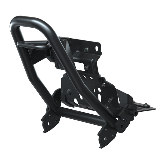
PLOW MOUNT KIT
P/N 2884764
BEFORE YOU BEGIN
Read these instructions and check to be sure all parts and tools are accounted for. Please retain these
installation instructions for future reference and parts ordering information.
APPLICATION
Verify accessory fitment at www.polaris.com.
KIT CONTENTS
REF
QTY
PART DESCRIPTION
1
1
Mount Plate
2
1
Mid Mount
3
1
Bracket-Bumper Support, Upper
4
1
Handle Lock
5
1
Tightening Plate
6
1
Fairlead Adapter Plate
7
1
Lower Side Support Bracket
8
1
Kickstand Lever
Instr 9931129
Rev 01 2020-08
AVAILABLE
P/N AVAILABLE
SERVICE KIT
SEPARATELY
1026122
n/a
1026123
n/a
5265124
n/a
n/a
n/a
n/a
n/a
n/a
n/a
n/a
n/a
n/a
n/a
Page 1 of 8
Advertisement

Related Manuals for Polaris 2884764


Summary of Contents for Polaris 2884764
- Page 1 BEFORE YOU BEGIN Read these instructions and check to be sure all parts and tools are accounted for. Please retain these installation instructions for future reference and parts ordering information. APPLICATION Verify accessory fitment at www.polaris.com. KIT CONTENTS AVAILABLE PART DESCRIPTION...
-
Page 2: Tools Required
PART DESCRIPTION P/N AVAILABLE AVAILABLE SEPARATELY SERVICE KIT Weldment Plate 2208483 Screw–Hexflange, M8 x 1.25 x 25 2208483 Screw–Hexflange, M6 x 1.0 x 30 2208483 Screw–Hexflange, M10 x 1.25 x 25 2208483 Screw–Hex, M10 x 1.5 x 25 2208483 Nut–Flange, Nylon Locking, M8 x 1.25 2208483 Washer–10.5 x 20 x 2 2208483... - Page 3 2. Move hood forward to remove from vehicle. 3. Disconnect headlight connectors and accent light connectors. ACCESSORY INSTALLATION 4. Install upper bumper bracket support using screws and weldment plate 1. Remove and keep two screws . Remove winch cover. 2. Remove and keep eight screws to remove front fascia.
- Page 4 5. Install fairlead. 7. Install tightening plate with washers and screws • If fairlead uses standard mounting holes then install winch fairlead onto mounting plate using screws and nuts • If fairlead uses inner holes then fairlead adapter is required. Install fairlead and fairlead adapter to mounting plate using screws and nuts 8.
- Page 5 CENTER HOOD PANEL INSTALLATION 2. Install front fascia with six screws 1. Move hood rearward. 3. Install two screws 2. Turn quarter-turn fasteners to lock hood to vehicle. 4. Install optional winch cover with screws Instr 9931129 Rev 01 2020-08 Page 5 of 8...
-
Page 6: Operation
OPERATION HOOK UP ASSEMBLY 3. Insert split pins and bend to secure. 1. Attach plow hookup. 4. Install winch link into plow assembly. 2. Insert pins 5. Attach winch to winch link. IMPORTANT The first adjustment requires kickstand height adjustment, depending on ground clearance. It may be necessary to repeat this exercise if accessories are added that affect ground clearance. - Page 7 4. Pull up on handle. 3. Rotate assembly up by hand until hook engages with upper mount of plow mount plate. If hook does not fully engage check for snow and ice accumulation on lower pins of the mount plate. The kickstand should be off of the ground.
- Page 8 ADJUSTMENT OF AUTO RETRACTING 5. Lower plow to the ground and adjust nut on bottom of winch link as required. KICKSTAND 6. Repeat steps until maximum lift height is achieved. CAUTION KICKSTAND ADJUSTMENT The plow could become disconnected during adjustment. Always lower plow to the ground when CAUTION making adjustments to avoid injury.
Need help?
Do you have a question about the 2884764 and is the answer not in the manual?
Questions and answers