Table of Contents
Advertisement
Quick Links
Downloaded from
Elcodis.com
electronic components distributor
IDX (IDX 4803
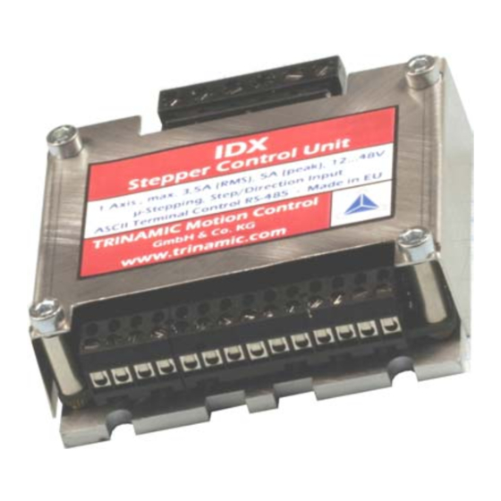
STEPPER motor controller/driver modules
IDX / IDX 4803: 3.5A RMS (5A peak) / 48V
IDX 7505: 5.0A RMS (7A peak) / 75V
with RS485 and step-/ direction interface
Trinamic Motion Control GmbH & Co. KG
and IDX
Manual
Sternstraße 67
D – 20357 Hamburg, Germany
Phone +49-40-51 48 06 – 0
FAX: +49-40-51 48 06 – 60
http://www.trinamic.com
INFO@TRINAMIC.COM
7505)
Advertisement
Table of Contents

Related Manuals for Trinamic IDX 4803


Summary of Contents for Trinamic IDX 4803
- Page 1 IDX 7505) Manual STEPPER motor controller/driver modules IDX / IDX 4803: 3.5A RMS (5A peak) / 48V IDX 7505: 5.0A RMS (7A peak) / 75V with RS485 and step-/ direction interface Trinamic Motion Control GmbH & Co. KG Sternstraße 67 D –...
-
Page 2: Table Of Contents
Setting up the module ......................28 6.6.2 Parameterizing with RS485 ....................28 6.6.3 Motion Control........................28 Revision History ..........................29 Documentation Revision ......................29 Firmware Revision ........................29 Copyright © 2005, TRINAMIC Motion Control GmbH & Co. KG Downloaded from Elcodis.com electronic components distributor... - Page 3 Table 5.1: Maximum voltage regarding motor current and inductivity ..........12 Table 6.1: RS485 Commands ....................... 18 Table 6.2: Motor Current Examples for IDX / IDX 4803 ................ 19 Table 6.3: Failure readout in SPI mode....................19 Table 6.4: StallGuard..........................20 Table 6.5: Limit switch ...........................
-
Page 4: Features
1 Features The TRINAMIC IDX is a small and rugged step / direction stepper motor driver system with a supply voltage of up to 50V and up to 3.5A RMS motor coil current (up to 75V and up to 5A RMS for IDX 7505). -
Page 5: Life Support Policy
Specifications subject to change without notice. Copyright © 2005, TRINAMIC Motion Control GmbH & Co. KG Downloaded from Elcodis.com electronic components distributor... -
Page 6: Electrical And Mechanical Interfacing
Opto-decoupled input (negative terminal): Tie to opto-coupler negative supply voltage to disable motor driver Common 5…24V, Opto-coupler positive supply voltage Table 3.2: Controls Pinning Copyright © 2005, TRINAMIC Motion Control GmbH & Co. KG Downloaded from Elcodis.com electronic components distributor... -
Page 7: Dimensions
Both connectors are RIA connectors. Power and motor: 6 pin connector RM 5.0 (07_06_RM5) Control: Two 4 pin and one 6 pin connectors RM 3.5, (2x 166_04_RM3.5, 1x 166_06_RM35) Copyright © 2005, TRINAMIC Motion Control GmbH & Co. KG Downloaded from Elcodis.com... -
Page 8: Operational Ratings
Output current on GPO (open collector) -150 Environment temperature °C Temperature of case back (cooling °C plate), operating Table 4.1: Operational Ratings (Orange: Different values for IDX 7505) Copyright © 2005, TRINAMIC Motion Control GmbH & Co. KG Downloaded from Elcodis.com electronic components distributor... -
Page 9: Practical Maximum Motor Current Ratings
4.1 Practical maximum motor current ratings The IDX 7505 (IDX 4803) uses eight high power 80V (60V) transistors with low internal on resistance of only 15mOhm (24mOhm) to drive the motor. Due to this, power loss is just a few watts at maximum current. -
Page 10: Step, Direction And Disable Inputs
Figure 4.1: Step, Direction and Disable Inputs Examples: = 5V undefined OPTON OPTOFF = 0V 1.5V 4.0V STEP = 20V undefined OPTON OPTOFF = 0V 16.5V 19.0V STEP Copyright © 2005, TRINAMIC Motion Control GmbH & Co. KG Downloaded from Elcodis.com electronic components distributor... -
Page 11: Getting Started
The minimum supply voltage has to be above two times the nominal motor voltage. ⋅ ≤ ≤ ⋅ ⋅ COIL MOTOR Copyright © 2005, TRINAMIC Motion Control GmbH & Co. KG Downloaded from Elcodis.com electronic components distributor... -
Page 12: Chopper Mode 2 (Phase)
48 V 4000 mH 36 V 0.3 A 2666 mH 24 V 1333 mH 12 V Table 5.1: Maximum voltage regarding motor current and inductivity Copyright © 2005, TRINAMIC Motion Control GmbH & Co. KG Downloaded from Elcodis.com electronic components distributor... -
Page 13: Figure 5.1: Maximum Voltage Regarding Motor Current And Inductivity
800.0 600.0 400.0 200.0 ICOIL /A If in doubt, please start with a lower supply voltage and check motor heating when raising the voltage. Copyright © 2005, TRINAMIC Motion Control GmbH & Co. KG Downloaded from Elcodis.com electronic components distributor... -
Page 14: Connecting Motor And Power Supply
(i.e. more than 2-3m), use a robust 4700µF (IDX 7505) or 2200µF (IDX 4803) or similar additional filtering capacitor located near to the motor driver unit. Choose the capacitor voltage rating fitting to the maximum operating voltage. -
Page 15: Connections For Step / Direction- Mode
Velocity Deceleration Acceleration const. PWR 12...50 V Figure 5.3: Contacts for Step-Direction The maximum step frequency is 350 kHz (limited by the opto couplers). Copyright © 2005, TRINAMIC Motion Control GmbH & Co. KG Downloaded from Elcodis.com electronic components distributor... -
Page 16: Connections For Rs485 Interface
The RS485-mode allows for configuration of motor parameters as well as remote control of the motor. 5.5.1 Interface installation To connect the module to a PC a RS485 interface is required, for example TRINAMIC’s new USB-2- 485 or any other RS485 adapter, like the standard RS232 to RS485-converters. Input A has to be connected to RS485A of the IDX and Input B with RS485B. -
Page 17: Functional Description
A Reset to factory default is possible. Default address byte is “A” and default baud rate is 9600 baud. This mode can only be used with an appropriate RS485 interface. Commands are sent with a terminal program, refer 5.5. Copyright © 2005, TRINAMIC Motion Control GmbH & Co. KG Downloaded from Elcodis.com... -
Page 18: Rs485 Commands
4: min), Refer 6.2.1.11 Table 6.1: RS485 Commands Examples: Set chopper mode to SPI Mode: AM 0 ⇒ ENTER Read out the actual mode Am ⇒ ENTER Copyright © 2005, TRINAMIC Motion Control GmbH & Co. KG Downloaded from Elcodis.com electronic components distributor... -
Page 19: Examples For Test Move
0.50A 0.5A 0.35A Table 6.2: Motor Current Examples for IDX / IDX 4803 *) Not possible for chopper mode 2. 6.2.1.3 Failure Readout (E) The IDX provides a full driver failure analysis in SPI mode (8 Bit). The returned bit assignments are as... -
Page 20: Stallguard (G)
1: GPO is active (LED on) 1: Output is changed at end of reference run Table 6.6: Output adjustment Figure 6.1: GPO wiring scheme Copyright © 2005, TRINAMIC Motion Control GmbH & Co. KG Downloaded from Elcodis.com electronic components distributor... -
Page 21: I/Os Readout (Q)
AV –50000 ⇒ ENTER: Accelerates motor to given velocity ⇒ ENTER: Accelerates motor to velocity zero (standstill) and delays echoing of carriage AV 0 1 return until target velocity has been reached Copyright © 2005, TRINAMIC Motion Control GmbH & Co. KG Downloaded from Elcodis.com electronic components distributor... -
Page 22: Store Parameters To Eeprom (W)
The minimum supply voltage has to be above two times the nominal motor voltage. ⋅ ≤ ≤ ⋅ ⋅ COIL MOTOR It uses a chopper frequency of about 36kHz. Copyright © 2005, TRINAMIC Motion Control GmbH & Co. KG Downloaded from Elcodis.com electronic components distributor... -
Page 23: Chopper Mode 1 (Pwm)
If x is in the range 0.5 to 1.0, try operating your motor and check if motor or driver gets too hot. If x is above 1.0, choose one of the other chopper modes. See also 5.1.1.3 for graphical demonstration. Copyright © 2005, TRINAMIC Motion Control GmbH & Co. KG Downloaded from Elcodis.com... -
Page 24: Chopper Mode 3 (Phase And Spi)
3 should be preferred if a combination of high accuracy at slow movements and high speed is needed. Copyright © 2005, TRINAMIC Motion Control GmbH & Co. KG Downloaded from Elcodis.com... -
Page 25: Step / Direction
Description: The Direction signal changes the motors rotation from clockwise (CW) to counterclockwise (CCW) and vice versa. Function Table: open wire = 5…24V motor CW motor CCW Copyright © 2005, TRINAMIC Motion Control GmbH & Co. KG Downloaded from Elcodis.com electronic components distributor... -
Page 26: Step
All settings are now at factory default. pin 1 pin 3 (quadratic) Figure 6.4: Reset to factory default Copyright © 2005, TRINAMIC Motion Control GmbH & Co. KG Downloaded from Elcodis.com electronic components distributor... -
Page 27: Firmware Update
1. Choose your RS485 connection. 2. Select your Module ID (default is A). 3. Load the new firmware file (e.g. IDX_V1.08.hex), to download from www.trinamic.com. 4. Start the update process. At the end of the update process check your firmware version with command “AX”. -
Page 28: Option: Pseudo Dc-Motor Mode (Not Supported By Software Yet)
Change the voltage at GPI between 7…48V. The motor will accelerate and decelerate relative to the specified zero point. Additional parameters like resolutions of microsteps can be stored in the EEPROM. Copyright © 2005, TRINAMIC Motion Control GmbH & Co. KG Downloaded from Elcodis.com... -
Page 29: Revision History
Added chopper modes 3 and 4, modified V command, corrected RS485 options bug (always echoing of CR at earlier versions) Table 7.2: Firmware Revisions Copyright © 2005, TRINAMIC Motion Control GmbH & Co. KG Downloaded from Elcodis.com electronic components distributor...
Need help?
Do you have a question about the IDX 4803 and is the answer not in the manual?
Questions and answers