Advertisement
Table of Contents
You will need
•
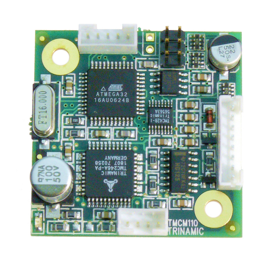
Your TMCM-110 stepper motor controller
and driver module
•
A stepper motor with 1A RMS coil current
•
Interface (RS232, RS485, CAN or IIC)
suitable to your TMCM-110 version, with
cables and maybe converter supplied.
•
Power supply for 12V to 30V
•
Tmcl Ide program and PC
•
Equipment to connect motor and TMCM-
110, maybe soldering tools.
Starting up:
1. Connect RS232 pin 2 (PC-TxD) to pin 4 (110-RxD) and pin 3
(PC-RxD) to pin 5. Use other interfaces equivalent.
2. Connect RS232 cable to PC.
3. Connect power supply to TMCM-110
•
Power supply (+) to pin 2
•
Ground (GND) to pin 1
4. Connect stepper motor to 4 pin connector
5. Turn power ON. The LED of the module flashes and the motor
is powered (standby current flows) but in standstill. If this does
not occur switch power OFF and check your connections and
power supply.
6. Start the TMCL IDE program (see other side of the sheet how
to configure the connection and use the IDE).
7. Type following into the open window:
//A simple example for using TMCL and the TMCL-IDE
SAP 4, 0, 100
Loop: MVP ABS, 0, 15000
WAIT POS, 0, 0
WAIT TICKS, 0, 200
MVP ABS, 0, 0
WAIT POS, 0, 0
WAIT TICKS, 0, 100
JA Loop
8. Click the "Assemble" icon, then click the "Download" icon to
download the code to the TMCM-110. Click the "Run" icon. The
downloaded program will now be executed
9. Click stop button and start "TMCL Direct Mode" to issue
following commands:
•
ROR rotate right, Motor 0, value 500 → Click Execute
The motor is rotating now.
•
MST motor stop, Motor 0 → Click Execute
First steps are made.
refer to next page and the TMCM-110 Manual.
Wiring note: The TMCM-110 comes with a 4pin, a 5pin and an 8
pin JST PHR-connector with about 20cm cables for each pin. If you
have a PANdrive the TMCM-110 is mounted to a motor and no
extra motor connection is needed.
Copyright © 2006, TRINAMIC Motion Control GmbH & Co. KG
Start into stepper motor motion systems
Italic and green lines can be neglected for the PD-110.
Start with power supply OFF.
//Set the maximum speed
//Move to position 15000
//Move back to position 0
//Infinite Loop
For other commands of the TMCM-110
Precautions
•
Do not connect or disconnect the motors while powered
•
Do not mix up connections or short-circuit pins
•
Avoid bundling IO wires with motor power wires, as this
may cause noise pickup from the motor.
•
Do not exceed the maximum power supply of 30V.
•
If attaching the TMCM-110 directly to a motor leave at
least a 5mm gap for air cooling.
use null modem
cable, otherwise
6
switch pins 2 and 3
2
RS232
Power-
2 3
supply
12..30V
-
+
1
3
Pin 1
TMCM-110
4
Motor
9
www.trinamic.com
5
8
Advertisement
Table of Contents

Subscribe to Our Youtube Channel
Related Manuals for Trinamic TMCM-110


Summary of Contents for Trinamic TMCM-110
- Page 1 TMCM-110 Manual. Motor Wiring note: The TMCM-110 comes with a 4pin, a 5pin and an 8 pin JST PHR-connector with about 20cm cables for each pin. If you have a PANdrive the TMCM-110 is mounted to a motor and no extra motor connection is needed.
- Page 2 If communication is established the TMCM-110 is automatically by clicking “Stop button” and detected. Issue a command by choosing Instruction, Type, Motor, start “Direct Mode”. Value and press Execute to send it to the TMCM-110. Following commands can be Commands: Troubleshooting: included into a program or used in “Direct Mode”.
Need help?
Do you have a question about the TMCM-110 and is the answer not in the manual?
Questions and answers