Table of Contents
Advertisement
Quick Links
Advertisement
Table of Contents

Related Manuals for Trinamic IDX


Summary of Contents for Trinamic IDX
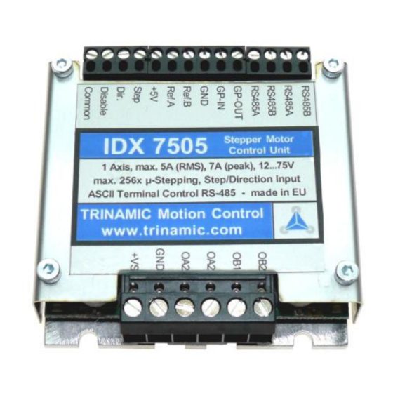
- Page 1 IDX (IDX and IDX 7505) Manual STEPPER motor controller/driver modules IDX: 3.5A RMS (5A peak) / 48V IDX 7505: 5.0A RMS (7A peak) / 75V with RS485 and step-/ direction interface Trinamic Motion Control GmbH & Co. KG Sternstraße 67 D –...
- Page 2 5.12.1 Setting up the module ......................... 29 5.12.2 Parameterizing with RS485 ........................29 5.12.3 Motion Control ............................29 Revision History ................................30 Documentation Revision ..........................30 Firmware Revision ............................30 Copyright © 2005-2008, TRINAMIC Motion Control GmbH & Co. KG...
- Page 3 Table 3.1: Power and Motor Pinning ..........................6 Table 3.2: Controls Pinning ..............................6 Table 4.1: Operational Ratings (Orange: Different values for IDX 7505)............... 8 Table 4.2.1: Practical motor current limitations for IDX 7505 .................. 9 Table 5.1: Maximum voltage regarding motor current and inductivity .............. 12 Table 5.2: RS485 Commands ............................
-
Page 4: Features
50V and up to 3.5A RMS motor coil current (up to 75V and up to 5A RMS for IDX 7505). It can be controlled via an RS-485 interface. Up to 256 micro steps are supported for either high accuracy or high speed. -
Page 5: Life Support Policy
Specifications are subject to change without notice. Copyright © 2005-2008, TRINAMIC Motion Control GmbH & Co. KG... -
Page 6: Electrical And Mechanical Interfacing
Opto-decoupled input (negative terminal): Polarity determines motor direction Disable Opto-decoupled input (negative terminal): Tie to opto-coupler negative supply voltage to disable motor driver Common 5…24V, Opto-coupler positive supply voltage Table 3.2: Controls Pinning Copyright © 2005-2008, TRINAMIC Motion Control GmbH & Co. KG... -
Page 7: Dimensions
Connectors Both connectors are RIA connectors. Power and motor: 6 pin connector RM 5.0 (07_06_RM5) Control: Two 4 pin and one 6 pin connectors RM 3.5, (2x 166_04_RM3.5, 1x 166_06_RM35) Copyright © 2005-2008, TRINAMIC Motion Control GmbH & Co. KG... -
Page 8: Operational Ratings
Output voltage on GPO (open collector) Output current on GPO (open collector) -150 Environment temperature °C Temperature of case back (cooling plate) °C Table 4.1: Operational Ratings (Orange: Different values for IDX 7505) Copyright © 2005-2008, TRINAMIC Motion Control GmbH & Co. KG... -
Page 9: Practical Maximum Motor Current Ratings
Practical maximum motor current ratings The IDX 7505 (IDX) uses eight high power 80V (60V) transistors with low internal on resistance of only 15mOhm (24mOhm) to drive the motor. Due to this, power loss is just a few watts at maximum current. -
Page 10: Step, Direction And Disable Inputs
E: Emitter Step Figure 4.1: Step, Direction and Disable Inputs Examples: = 5V undefined OPTON OPTOFF = 0V 1.5V 4.0V STEP = 20V undefined OPTON OPTOFF = 0V 16.5V 19.0V STEP Copyright © 2005-2008, TRINAMIC Motion Control GmbH & Co. KG... -
Page 11: Getting Started
. A higher value would COIL, MAX MOTOR lead to an excess of motor rating. The minimum supply voltage has to be above two times the nominal motor voltage. COIL MOTOR Copyright © 2005-2008, TRINAMIC Motion Control GmbH & Co. KG... -
Page 12: Chopper Mode 2 (Phase)
4.8 mH 48 V 2.4 mH 24 V 12.5 mH 75 V 0.3 A 8 mH 48 V 4 mH 24 V Table 5.1: Maximum voltage regarding motor current and inductivity Copyright © 2005-2008, TRINAMIC Motion Control GmbH & Co. KG... -
Page 13: Figure 5.1: Maximum Voltage Regarding Motor Current And Inductivity
) is possible to drive the motor in this mode. ICOIL /A Check your motor data sheet, please. If in doubt, please start with a lower supply voltage and check motor heating when raising the voltage. Copyright © 2005-2008, TRINAMIC Motion Control GmbH & Co. KG... -
Page 14: Connecting Motor And Power Supply
(i.e. more than 2-3m), use a robust 4700µF (IDX 7505) or 2200µF (IDX) or similar additional filtering capacitor located near to the motor driver unit. -
Page 15: Emv Considerations
5.5.1 Interface installation To connect the module to a PC a RS485 interface is required, for example TRINAMIC’s new USB-2-485 or any other RS485 adapter, like the standard RS232 to RS485-converters. Input A has to be connected to RS485A of the IDX and Input B with RS485B. -
Page 16: Control With Terminal Program
, 2008) 5.5.2 Control with terminal program Having installed the hardware, the IDX can be controlled with any terminal program, like HyperTerminal that comes with MS-Windows. Following steps are described for HyperTerminal but are similar for the other terminal programs: Start HyperTerminal A window for a new connection opens. -
Page 17: Functional Description
RS485 Control Interface The RS485 interface can control all functions of the IDX. It is possible to change parameters, with this interface which are also valid in the other modes like max. velocity or acceleration. The parameters can be written to the EEPROM to obtain the changes after a restart. -
Page 18: Rs485 Commands
“Set motor current”. Microstep Sets the maximum microstep resolution (0: Z, z 0..6 Resolution max; 6: min), Refer 5.8.1.11 Table 5.2: RS485 Commands Copyright © 2005-2008, TRINAMIC Motion Control GmbH & Co. KG... -
Page 19: Examples For Test Move
Table 5.3: Motor Current Examples for IDX *) Not possible for chopper mode 2. 5.8.1.3 Failure Readout (E) The IDX provides a full driver failure analysis in SPI mode (8 Bit). The returned bit assignments are as follows: Name Function... -
Page 20: Stallguard (G)
To activate a reference switch set the appropriate bit to 1. When motor stops the position counter is set to zero. Example: AL 8 ENTER : Activates REF_B = 1. When destination reached motor stops and position counter is set to zero. Copyright © 2005-2008, TRINAMIC Motion Control GmbH & Co. KG... -
Page 21: Output Setting (O)
The parameter ‘U’ changes the baud rate of the module for RS485 communication. Parameter U Baud rate 9600 baud 14400 baud 19200 baud 28800 baud 38400 baud 57600 baud 76800 baud 115200 baud Table 5.9: Baud rate Copyright © 2005-2008, TRINAMIC Motion Control GmbH & Co. KG... -
Page 22: Velocity Mode (V)
Output adjustment (set by command O) RS485 parameters (set by command U) Microstep resolution (set by command Z) Example: ENTER: All actual parameters from list above are stored to EEPROM. Copyright © 2005-2008, TRINAMIC Motion Control GmbH & Co. KG... -
Page 23: Microstep Resolution (Z)
COIL, MAX MOTOR of motor rating. The minimum supply voltage has to be above two times the nominal motor voltage. COIL MOTOR It uses a chopper frequency of about 36kHz. Copyright © 2005-2008, TRINAMIC Motion Control GmbH & Co. KG... -
Page 24: Chopper Mode 1 (Pwm)
If x is in the range 0.5 to 1.0, try operating your motor and check if motor or driver gets too hot. If x is above 1.0, choose one of the other chopper modes. See also 5.1.1.3 for graphical demonstration. Copyright © 2005-2008, TRINAMIC Motion Control GmbH & Co. KG... -
Page 25: Chopper Mode 3 (Phase And Spi)
4. This mode should only be used in very special occasions and mode 3 should be preferred if a combination of high accuracy at slow movements and high speed is needed. Copyright © 2005-2008, TRINAMIC Motion Control GmbH & Co. KG... -
Page 26: Step / Direction
Figure 5.8: Step-Direction signals and motor reactions 5.9.1 Direction Description: The Direction signal changes the motors rotation from clockwise (CW) to counterclockwise (CCW) and vice versa. Function Table: open wire = 5…24V motor CW motor CCW Copyright © 2005-2008, TRINAMIC Motion Control GmbH & Co. KG... -
Page 27: Step
Turn on the module and switch it off again to remove the short-circuit. All settings are now at factory default. pin 1 pin 3 (quadratic) Figure 5.10: Reset to factory default Copyright © 2005-2008, TRINAMIC Motion Control GmbH & Co. KG... -
Page 28: Firmware Update
IDX Manual (V1.15 / September 26 , 2008) 5.11 Firmware Update For Firmware update start the program TMCM013boot.exe contained in the IDX-Folder of your TMCTechLibCD or at www.trinamic.com: Figure 5.11: Firmware update tool Choose your RS485 connection. Select your Module ID (default is A). -
Page 29: Option: Pseudo Dc-Motor Mode (Not Supported By Software Yet)
GPI pin, as depicted. Figure 5.12: GPI wiring scheme However, there are two free places for 0805 SMD resistors to be equipped directly on the module IDX. To enable this mode solder use resistors as follows: Attention: Do not try to make changes on the board until you are absolutely sure. -
Page 30: Revision History
Mixed decay can be disabled without turning on StallGuard using G8 1.11 Improvement StallGuard improved by filtering 1.12 New option StallGuard also usable in step/direction mode (controls GPO then) Table 6.2: Firmware Revisions Copyright © 2005-2008, TRINAMIC Motion Control GmbH & Co. KG...
Need help?
Do you have a question about the IDX and is the answer not in the manual?
Questions and answers