
Related Manuals for ekwb EK-KIT HT Series


Summary of Contents for ekwb EK-KIT HT Series
- Page 1 For EK-KIT HT series units | 1st Revision, March 9th 2018 Starter Liquid Cooling Kit HARD TUBE 240 360 USER GUIDE...
- Page 3 If there is any problem, contact the shop where you have purchased the product to get a replacement or refund. 3. EKWB d.o.o. is not responsible for any damages due to external causes, including but not limited to, improper use, problems with electrical power, accident, neglect, alteration, repair, improper installation and improper testing.
-
Page 4: Table Of Contents
TABLE OF CONTENT SCOPE OF DELIVERY POSSIBILITIES OF EXPANDING THE SYSTEM REQUIRED TOOLS MAINTENANCE FREQUENTLY ASKED QUESTIONS QUICK INSTALLATION GUIDE TROUBLESHOOTING RADIATOR SPACE CONSTRAINT REQUIREMENTS GENERAL LIQUID COOLING PARTS CLEANING GUIDE DOZEN GOOD ADVICES FOR THE NEWCOMERS SUPPORT AND SERVICE LIQUID COOLING SYSTEM SOCIAL MEDIA GENERAL INFORMATION ON WATER BLOCK COMPATIBILITY... -
Page 5: Scope Of Delivery
SCOPE OF DELIVERY CPU water Block CPU Backplate mechanism Thermal grease CPU Mounting mechanism with AMD® mounting plate Fans Pump-Reservoir combo UNI Pump Bracket Compression fittings Radiator Coolant Tube ATX Bridging plug / 3 /... -
Page 6: Required Tools
Fan cable Y-splitter Adapter cable Installation manual Allen key REQUIRED TOOLS Phillips-head screwdriver Mixing bottle 1L Bottle of distilled water Filling bottle Silicon tube Heat gun / 4 /... -
Page 7: Radiator Space Constraint Requirements
RADIATOR SPACE CONSTRAINT REQUIREMENTS 26 mm (1,02 in) 120 mm (4,72 in) / 5 /... -
Page 8: Dozen Good Advices For The Newcomers
DOZEN GOOD ADVICES FOR THE NEWCOMERS 1. In order to lower shipping costs we have decided to enclose only the after the Radiator in the water loop. coolant concentrate for liquid cooling. Therefore you need to provide 1 liter 7. Generally, for optimal performance, the Pump should be positioned before (1L) of distilled water. -
Page 9: General Information On Water Block Compatibility
GENERAL INFORMATION ON WATER BLOCK COMPATIBILITY This CPU liquid cooling unit is pre-assembled for use with modern Intel desktop socket type motherboards. By default (out of the box) this water block supports the following CPU sockets: - Intel® Socket LGA-115x - Intel®... -
Page 10: Installing The Water Block
INSTALLING THE WATER BLOCK LGA-2066 SOCKET MOTHERBOARDS STEP 1 LGA-2011 M4 Prepare the foil bag with mounting mechanism, which is enclosed with the CPU Thumb Screw Thumb Screw water block delivery. Install four (4) specific LGA-2011 M4 thumb screws into four M4 threaded stubs on the LGA-2066 socket integrated latch mechanism (ILM). - Page 11 STEP 3 Take the waterblock and remove the sticker on the copper head. Align the water block over the mounting screws on the LGA-2066 motherboard with pre-installed CPU. Thumb nut Before proceeding with the installation It is mandatory to remove the protective foil from the backside of the water block.
-
Page 12: Lga-115X Socket Motherboards
LGA-115x SOCKET MOTHERBOARDS Outer part STEP 1 If already installed, please remove the motherboard from your computer and place it on an even surface with front facing down. STEP 2 Preparing backplate rubber gasket The enclosed rubber gasket is essential part of the backplate and mount- ing system and must be used every time you install this water block on your motherboard. - Page 13 STEP 5 Cleaning the CPU: Wipe the CPU’s contact surface (by using non–abrasive cloth or Q-tip, as shown on sample photo). Non-abrasive Applying thermal compound: EK recommends blob or line method of applying the cloth enclosed EK-TIM Ectotherm thermal compound to the CPU heat spreader (IHS) - see sample photo on right.
-
Page 14: Amd® Socket Motherboards
AMD® SOCKET MOTHERBOARDS M4x14 Screws STEP 1 Replacing the mounting plate: Place the water block on a neven surface and remove the four Intel® socket AMD® socket M4x14 DIN 7991 screws attaching the copper base to the top mounting plate mounting plate using 2,5mm Allen key in counter-clockwise direction. - Page 15 STEP 4 Removing of the original plastic hold-down clamps UNC 6-32 AMD® factory backplate and the factory backplate: Screws Using Philips-head screwdriver remove the four UNC 6-32 screws securing the original plastic hold-down clamps around the socket as shown on the sketch. Re- move the original AMD®...
- Page 16 STEP 7 M4 Thumb Screw Install four (4) M4 thumb screws onto your motherboard. It is mandatory to put 0.7mm plastic washer underneath each of the M4 thumb screws. Tighten the screws to the metal backplate until you reach the end of the thread. Using tools (such as pliers) is not recommended.
- Page 17 STEP 9 Fitting Ring With EK-Supremacy MX series water blocks it is mandatory to use the port that is nearest to the O-ring center of the water block as INLET port. Mixing the Fitting Barb ports may result in poor thermal performance of Inlet port the water block.
-
Page 18: Installing The Radiator And Fans
INSTALLING THE RADIATOR AND FANS OPTION #1: UNC 6-32 x 30 screw INSTALLING THE RADIATOR AND FANS STEP 1 Install the fans on the radiator. Ideally, the radiator should either: A) receive the coldest air possible (by placing the radiator on the air inlet) or B) serve as an overall hot air exhaust (by placing the Radiator radiator on the exhaust). -
Page 19: Installing The Radiator And Fans In One Go
STEP 4.: Install the compression fitting on both G1/4 extender openings on the radiator. Tighten Fitting Barb the fitting barbs in clockwise direction until the gasket underneath is compressed. The installation of the radiator and radiator cooling fans is now complete. Fitting Ring OPTION #2: O-ring... -
Page 20: Installing The Pump-Reservoir Unit
INSTALLING THE PUMP-RESERVOIR UNIT STEP 1 The KIT comes with combined pump and reservoir unit with pre- installed anti-vibration decouplers. Pump-reservoir combo unit Take the unit and place it on the EK-UNI Pump Bracket. Secure it from the bottom side using four M4x4 screws and PVC washers. - Page 21 STEP 3 Secure the M4x6 screws (from the previous step) with four M4 nuts and PC Chassis PVC washers. Tighten them using 2,5mm Allen key with the screws. Make sure that the screws are holding tight but do not exag- gerate with the force applied.
-
Page 22: Bending Tube
BENDING TUBE STEP 1 First you need to put silicon rod inside your ACRYLIC tube. You can use soap and a bit of water on silicon rod for easier installation.. STEP 2 Use industrial fan to heat up the acrylic tube. You need to rotate the tube while heating. - Page 23 STEP 4 You need to cut the tube to desired length. Use a fine hacksaw or equivalent. STEP 4 STEP 5 When finished you can use the tube reamer or sandpaper to chamfer the edges for easier installation into the fittings. STEP 5 / 21 /...
-
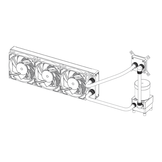
Page 24: Connecting The Tubing
CONNECTING THE TUBING If you are expanding your loop with additional liquid WATERBLOCK COLD AIR cooling components please proceed to Page 30, chapter POSSIBILITIES OF EXPANDING THE SYSTEM. STEP 1 RADIATOR In order to successfully route the tubing it is recommended with FANS that you check the water cooling scheme on the right picture. - Page 25 STEP 3 If you have assembled the components according to this instal- lation manual you should have all the compression fittings in- Fitting Ring stalled. In order to install the tubing onto the compression fittings you will have to remove the fitting rings by screwing it in counter-clockwise direction. O-ring STEP3 STEP 4...
-
Page 26: Electrical Connections
STEP 5.: Slide the fitting ring towards the barb and tighten it in clockwise direction as far as it goes. Repeat the procedure on all the fittings in order to connect the water cooling loop. The liquid cooling loop components are now connected and the cooling cir- cuit is now complete. -
Page 27: Connecting The Fans
CONNECTING THE FANS STEP 1 To connect all the fans to a single fan header you might need to use EK- Cable Y Splitter. Connect the female connectors from the fans with male connectors on the fan splitter cable. STEP 1 STEP 2 Connect the female EK-Cable Y splitter connector to the male connector header located on the motherboard. -
Page 28: Recommended Filling And Leak-Testing Procedure
RECOMMENDED FILLING AND LEAK- TESTING PROCEDURE Power supply ATX cable STEP 1 EK-ATX It is mandatory to do the following: Bridging Plug 1. Disconnect all PSU power connectors (4/8-pin ESP, 24-pin ATX, PCI-express power, SATA power) in your computer. 2. Plug the EK-ATX Bridging plug (enclosed) to your 24-pin ATX PSU cable which allows jump starting your computer. -
Page 29: Filling The System For The First Time
FILLING THE SYSTEM FOR THE FIRST TIME STEP 1: Preparing the cooling liquid. The coolant comes in concentrated form. In order to prepare the cooling liquid you must take a 100ml clear coolant concentrate, which is enclosed with the kit, and mix it with 900mL of distilled water. Make sure you mix the mixture properly before pouring it into the water cooling loop. - Page 30 STEP 4 When you turn on the power supply the coolant should be pushed from the reservoir to other water cooling components, therefore you have to fill the coolant continuously while the pump is running. Alternatively you can cycle (turn on and of) the power supply in few second intervals to speed up the air bleeding process.
-
Page 31: Draining Of The Loop
DRAINING OF THE LOOP STEP 1 Before disassembling the water cooling loop it is mandatory turn off your computer and pull the power cord from the socket. Prepare some paper towels and stack them over the hardware. Unscrew the reservour top. STEP 2 Use filling bottle to drain the loop. -
Page 32: Possibilities Of Expanding The System
POSSIBILITIES OF EXPANDING THE SYSTEM The best part of custom water cooling loop is that the system can be extended and the cooling capacity can be extended almost without limitations. For maximum performance, the rule of thumb is to use at least one 120mm radiator (section) per each water cooled component plus one ‘spare’. -
Page 33: Maintenance
STEP 2 Measure the length of the tube that is needed to connect the CPU to GPU water block and the GPU water block to the pump-reservoir unit. You can use a hacksaw or equivalent to cut the tube. You may need additional tubing to connect the water block. Attach the tube onto the both fitting barbs until it sits firmly. -
Page 34: Frequently Asked Questions
FREQUENTLY ASKED QUESTIONS Is this kit, namely the water block, compatible with nar- row server type LGA-2011 motherboard? How about old- What flow rates are to be expected with EK-KIT HARD TUBE? er LGA-1366 and -755? A: This kit typically operates at about 180L/h. A: Narrow server type LGA-2011 is not supported by default –... - Page 35 What thermal performance is to be expected from the EK-KIT HT unit? A: The nominal cooling capacity of the EK-KIT S units is listed in the table below: dT=10K dT=15K KIT HT240 * 255W 383W KIT HT360 * 383W 574W * = Vardar 120 @ 1850rpm The nominal capacity tells how much heat is the kit unit able to move with 10°C (10K) or 15°C (15K) increase in liquid temperature over ambient.
-
Page 36: Troubleshooting
CPU to the maximum, flow rates are very low. Visually inspect the water block internals for any buildup or contamination and clean EKWB deems der8auer Delid Die Mate tool safe to be used by the system if necessary. In case the water block with translucent acrylic top experts for de-lidding of the Intel Skylake CPUs. -
Page 37: General Liquid Cooling Parts Cleaning Guide
THE COOLER IS TOO LOUD The Predator unit is equipped with fast-spinning EK-Vardar high-static pres- General Gigabyte Z270/X99 motherboard guide: sure PWM controlled fans, which run at very high speed if the UEFI/BIOS is 1. Enter UEFI and go to M.I. T . - > PC Health Status not set to control fan speed. - Page 38 Upon cleaning is it necessary to flush the water blocks in water and rinse them Algae- or dirt deposits may be rubbed out using soft cloth in com- with distilled water. After rinsing we recommend soaking the water blocks in bination with warm, soapy water.
-
Page 40: Support And Service
SUPPORT AND SERVICE For assistance please contact: http://support.ekwb.com/ EKWB d.o.o. Pod lipami 18 1218 Komenda Slovenia - EU SOCIAL MEDIA EKWaterBlocks @EKWaterBlocks ekwaterblocks EKWBofficial ekwaterblocks...
Need help?
Do you have a question about the EK-KIT HT Series and is the answer not in the manual?
Questions and answers