
Related Manuals for Dräger Medical Vamos


Summary of Contents for Dräger Medical Vamos
- Page 1 RETURN TO THIS MANUAL'S TABLE OF CONTENTS RETURN TO CD-ROM TABLE OF CONTENTS Vamos Variable Anesthetic Gas Monitor Technical Documentation...
-
Page 2: Table Of Contents
Operating modes ..................9 Operating concept Power-up behavior ................10 Alarms ....................10 Menu structure ..................11 Simplified Vamos block diagram ............12 ILCA patient gas module Patient gas module structure ..............14 Sensor head function ................15 Sensor head operation ................ 20 Measured value units ................ - Page 3 Screen content release mode ............... 35 10.2 Entering the release code ..............35 Service Mode Starting the service mode Explanation of screen content .............. 38 Repair Instructions Service strategy VAMOS service programs Download program ................40 VISIA program ..................40 6494.340 Vamos Contents...
- Page 4 AMO FLOW ILCA PCB ................. 50 Options Optional battery ..................51 SpO2 option ..................52 Alarms and their meaning Behavior of Vamos in case of alarms ........... 53 General alarms ..................54 SpO2 measurement alarms ..............54 Gas measurement alarms ..............57 Vamos disassembly Housing rear panel disassembly ............
- Page 5 Text display ................... 88 Menu ..................... 89 Keys ...................... 93 Control knob ..................94 LEDs ..................... 95 Acoustic signal ..................96 1.10 Serial communication ................97 1.11 Processor ....................97 1.12 Software ....................98 1.13 Fan ......................99 6494.340 Vamos Contents...
- Page 6 RETURN TO THIS MANUAL'S TABLE OF CONTENTS RETURN TO CD-ROM TABLE OF CONTENTS Contents Schematics and Diagrams VAMOS block diagram Unit, general Spare parts used Safety Checks Test items Supply unit to customer ready for operation. Confirmation of test These steps are regarded as repair work and are therefore not included in the inspection service price.
-
Page 7: Introduction
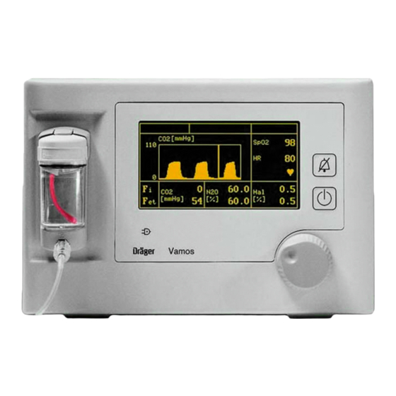
2 Central control knob for selection and Power indicator lamp confirmation Mains voltage = green Battery operation = yellow 3 Standby Key Water trap WaterLock 4 Key for silencing the alarm sound for Connection for sampling line 2 minutes 6494.340 Vamos Version 3.0 Function Description... -
Page 8: Screen Content
12 Connection for RS 232 interface Screen content SpO2 ♥ [mmHg] Key to possible screen content Alarm window Window for real-time curve Status window Displayed parameter 3, 4, 5, Parameter window Scaling of real-time curve 6, 7 6494.340 Vamos Version 3.0 Function Description... -
Page 9: Operating Modes
The light in the standby key should come on. In "Standby" mode the pump of the ILCA module is off. AC mains Vamos is in standby mode or in measuring mode and is powered supply from the desktop power pack. The power-on indicator light should operation: turn green. -
Page 10: Power-Up Behavior
LEDs are actuated one after the other. LED sequence: Standby, silence, advisory, alarm, standby..Standby screen Alarms Vamos classifies alarm signals into three priorities, identified by up to three different exclamation marks. Alarm messages with a higher priority supersede those with a lower priority. Alarm priority... -
Page 11: Menu Structure
Slow Normal Fast ---> Language ---> Config. high Brightn. 1200 Medibus 9600 (Baud) 19200 ---> Unit mmHg Vol% Range 0-75 0-110 Parameter ---> Gases Sound ---> Pulse Alarm SpO2 Fig. 1: Vamos menu structure 6494.340 Vamos Version 3.0 Function Description... -
Page 12: Simplified Vamos Block Diagram
Gas outlet Water trap ILCA Fig. 2: Vamos block diagram The ILCA patient gas module has no automatic anesthetic detector. The anesthetic being used must be specified by the user. Only one anesthetic may be used at any one time. The ILCA patient gas module conforms to the accuracy specified in the ISO standard. -
Page 13: Ilca Patient Gas Module
RETURN TO THIS MANUAL'S TABLE OF CONTENTS RETURN TO CD-ROM TABLE OF CONTENTS ILCA patient gas module Fig. 3: ILCA patient gas module components in Vamos 6494.340 Vamos Version 3.0 Function Description... -
Page 14: Patient Gas Module Structure
− AMO O2 GRAF PCB (with MFM software, MFM = Multi Function Module) − PCB mounting frame Sensor head Valve Pump MOPS PCB Mounting frame AMO FLOW ILCA PCB AMO ILCA PCB AMO O2 GRAF PCB Fig. 4: Components of the ILCA module 6494.340 Vamos Version 3.0 Function Description... -
Page 15: Sensor Head Function
2nd pre- (AMO ILCA amplifier EEPROM PCB) 8-channel multiplexer Pressure Track & Hold 8-channel A/D converter Temperature measurement and control Data Control signals Control signals Data MOPS PCB Fig. 5: Sensor head block diagram 6494.340 Vamos Version 3.0 Function Description... - Page 16 Fig. 6: Sensor head, sectional view Key to sensor head sectional view Light emitter (infrared range) 6, 7 PCBs Reflector Cuvette heating (FET) disc of light emitter Pressure sensor Cuvette Cuvette inlet and outlet Multispectrum detector 6494.340 Vamos Version 3.0 Function Description...
- Page 17 The setpoint is set via a digital serial potentiometer controlled by the MOPS PCB. The supply voltage is measured when the light emitter is off (low phase of light emitter modulation). 6494.340 Vamos Version 3.0 Function Description...
- Page 18 Each of the four beam paths represents a measuring channel. The basic design of the multispectrum detector is shown in the following diagram: 6494.340 Vamos Version 3.0 Function Description...
- Page 19 An absolute pressure sensor measures the pressure in the cuvette and, where appropriate, the ambient pressure (e.g. during zeroing). The pressure measurement is fast enough to represent fluctuations in respiratory pressure (T better than 200 ms). 6494.340 Vamos Version 3.0 Function Description...
-
Page 20: Sensor Head Operation
The sensor head software performs a self-test when the system starts up and continuously during measurement operation. In the event of an error the sensor software generates the relevant status message and shuts down the system if necessary. 6494.340 Vamos Version 3.0 Function Description... -
Page 21: Measured Value Units
1 vol.% * (760 /100 Torr/vol.%) = 7.6 Torr 1 Torr * (100/760 vol.%/Torr) = 0.1316 vol.% It is essential that this conversion of the concentrations should be distinguished from conversion of the pressures! 6494.340 Vamos Version 3.0 Function Description... -
Page 22: Pneumatic System
150 mL/min. R1 is large enough so that the pressure surges occurring in the cuvette do not impair the signal ratio and noise ratio in gas sampling. 6494.340 Vamos Version 3.0 Function Description... -
Page 23: Pump
Pump The pump flow is 150 mL/min ± 20 mL/min. The supply voltage is in the range from 2.5 V to 7.5 V DC at a current of up to 150 mA. 6494.340 Vamos Version 3.0 Function Description... -
Page 24: Mops Pcb
RETURN TO THIS MANUAL'S TABLE OF CONTENTS RETURN TO CD-ROM TABLE OF CONTENTS MOPS PCB Components (ILCA, AMO FLOW ILCA PCB, etc.) Distribution across ports switch MOPS PCB VAMOS PCB Fig. 9: Block diagram, MOPS PCB 6494.340 Vamos Version 3.0 Function Description... - Page 25 With this concept, different gas sampling modules (for example ILCA and IRIA) can be configured for specific customer needs using standard components. The MOPS PCB calculates values of the patient parameters and controls the sensor head signals. 6494.340 Vamos Version 3.0 Function Description...
-
Page 26: Amo Flow Ilca Pcb (Flow Controller)
RETURN TO THIS MANUAL'S TABLE OF CONTENTS RETURN TO CD-ROM TABLE OF CONTENTS AMO FLOW ILCA PCB (flow controller) MOPS PCB connector Fig. 10: Connection diagram, AMO FLOW ILCA PCB 6494.340 Vamos Version 3.0 Function Description... - Page 27 − Control parameters − Position of the digital potentiometer at which the differential pressure output DIFFDRUCK = 2.0 V − The voltage setpoint value at which the flow is 150 mL/min − OCCLUDED detection value 6494.340 Vamos Version 3.0 Function Description...
- Page 28 Valve The valve at X4 switches between ambient air and patient air. An optional valve at X5 is possible (is not mounted in VAMOS). The valve is non-polarized. There is no preferred position for the plug connector. A mechanical lock prevents the valves from detaching from the connector.
-
Page 29: Amo O2 Graf Pcb
RETURN TO THIS MANUAL'S TABLE OF CONTENTS RETURN TO CD-ROM TABLE OF CONTENTS AMO O2 GRAF PCB Fig. 11: Block diagram, AMO O2 GRAF PCB 6494.340 Vamos Version 3.0 Function Description... - Page 30 On the AMO O2 GRAF PCB the screen data are processed by a co-processor. The PCB controls and monitors the complete monitor function including the keypad, control knob, indicator lamps (LEDs), and SpO2 sensors. 6494.340 Vamos Version 3.0 Function Description...
-
Page 31: Vamos Pcb
RETURN TO THIS MANUAL'S TABLE OF CONTENTS RETURN TO CD-ROM TABLE OF CONTENTS VAMOS PCB Fig. 12: Block diagram, VAMOS PCB 6494.340 Vamos Version 3.0 Function Description... -
Page 32: Spo2 Pcb
PCB with no pre- amplifier. The PCB communicates via a serial port with the MOPS PCB. The PCB is electrically isolated from the rest of the system to 1.5 kV on the VAMOS PCB. The socket for the SpO sensor is mounted on the internal frame. -
Page 33: Desktop Power Pack
("CO line!?") is displayed on the screen. Desktop power pack − Input: 100 - 240 V AC − Output: 15 VDC, 2 A (4 kV separation) − Fuses: 2x 2 AT (Pico, internal) 6494.340 Vamos Version 3.0 Function Description... -
Page 34: Starting The Release Mode
Note that the key operation sequence is important for the start procedure. • First press and hold key A, then press and hold key B, and finally release key A and then key B. 6494.340 Vamos Version 3.0 Function Description... -
Page 35: Screen Content Release Mode
The release codes vary with the device number of Vamos. After replacing the complete ILCA module or the AMO O2 GRAF PCB DrägerService must store the device no. in Vamos (Visia software). If available, also release (activate) the SpO2 function. - Page 36 Enter the correct release code. − Valid code: A message appears in the dialog windows depending on the option released, e.g. "Agent option released". • Switch off Vamos and then on again. • Check whether the option has been activated. 6494.340 Vamos Version 3.0...
-
Page 37: Service Mode
RETURN TO CD-ROM TABLE OF CONTENTS Service Mode Starting the service mode Vamos Fig. 1: Starting the service mode using keys • While in standby mode, first press and hold key A and then press control knob B. Page 37 6494.340 VAMOS 10.2001 Service Mode... -
Page 38: Explanation Of Screen Content
13 Battery current (in mA). When the battery is being charged, the value has a positive sign. When VAMOS is powered from the battery, the value has a negative sign. 14 Battery status (the status can be entered in VISIA, version 1.06 or higher, and is decoded there) •... -
Page 39: Repair Instructions
ILCA test according to module PMS procedure. replacement, RAT- refurbish Lübeck Leak test. Repair of workshop components, if useful VDE test, function Calibration bench test according to PMS procedure, re-calibration (if necessary) Page 39 6494.340 Vamos 06.2002 Repair Instructions... -
Page 40: Vamos Service Programs
Two DrägerService programs are relevant to VAMOS: − Download program − VISIA program Both programs communicate with VAMOS via the RS 232C service interface and the RS 232 cable (7901808). Download program The download program can be found in the "Download" menu of the DrägerService software. - Page 41 RETURN TO CD-ROM TABLE OF CONTENTS Repair information list new Repair Information Described in: General Retrofitting of battery option Repair instructions, chapter 6.1 "Optional battery". Vamos disassembly Repair instructions, chapter 8 "Vamos disassembly" Page 41 6494.340 Vamos 06.2002 Repair Instructions...
-
Page 42: Hardware Configuration Of Vamos
RETURN TO THIS MANUAL'S TABLE OF CONTENTS RETURN TO CD-ROM TABLE OF CONTENTS Hardware configuration of VAMOS Fig. 1: Exploded view of VAMOS Page 42 6494.340 Vamos 06.2002 Repair Instructions... - Page 43 RETURN TO THIS MANUAL'S TABLE OF CONTENTS RETURN TO CD-ROM TABLE OF CONTENTS Sensor head Valve Pump MOPS PCB AMO FLOW ILCA PCB AMO ILCA PCB AMO O2 GRAF PCB Fig. 2: Components of the ILCA module Page 43 6494.340 Vamos 06.2002 Repair Instructions...
-
Page 44: Repair Components
”. Release the serial no. via ”Config” Page/Info tree/”Set Fab. No”. Only then will the release code be recognized as valid. The ILCA module needs to be removed from VAMOS to be able to replace ILCA components. − Pump Unscrew the fixing screw of the pump. Disconnect the power cable and, if necessary, the tubing. -
Page 45: Ilca
Therefore, observe the specified ranges when handling pneumatic elements such as syringes or pumps. The pressure in the cuvette chamber may be up to 200 mbar below the ambient pressure (low pressure in suction system). Page 45 6494.340 Vamos 06.2002 Repair Instructions... - Page 46 The sensor head attains its full accuracy when it has reached its operating temperature and a stable temperature distribution. In the worst case (start at lowest specified ambient temperature) the sensor head attains its specified accuracy no later than 4 minutes after power-on. Page 46 6494.340 Vamos 06.2002 Repair Instructions...
- Page 47 MOPS PCB. The supply voltage is measured correctly only when the light emitter is off, that is during the low phase of light emitter modulation. Page 47 6494.340 Vamos 06.2002 Repair Instructions...
-
Page 48: Pneumatic System
Length = 2.2 m , ID = 1 mm, pressure drop at 150 mL/min air: 35 mbar ± 7 mbar Typical pressure drop of the new Dräger water trap WAL: 25 mbar ± 10 mbar at 150 mL/min Page 48 6494.340 Vamos 06.2002 Repair Instructions... - Page 49 135 mL/min L=50 AMO PCB AMO ILCA PC FLOW ILCA L=10 Water see above trap L=50 L=10 L=150 15 mL/min L=110 Pressure sensor on AMO FLOW ILCA PC Fig. 3: Pneumatics connection diagram Page 49 6494.340 Vamos 06.2002 Repair Instructions...
-
Page 50: Amo Flow Ilca Pcb
The AMO FLOW ILCA PCB controls the pump and the valve(s). The PCB is controlled and powered by the MOPS PCB. The actual control of the pump flow is handled by the software of the controller on the MOPS PCB. Page 50 6494.340 Vamos 06.2002 Repair Instructions... -
Page 51: Options
ARRF-0026) pay attention to the following: • For the charging circuit to function properly, you need to replace the AMO O2 GRAF PCB (for location, see Fig. 2: Components of the ILCA module Page 51 6494.340 Vamos 06.2002 Repair Instructions... -
Page 52: Spo2 Option
The SpO2 option can be retrofitted in all units. A new Dura sensor always comes with a new SpO2 PCB to be installed. Dräger cannot order the PCB alone. Old Dura sensors might also not work with a new SpO2 PCB. Page 52 6494.340 Vamos 06.2002 Repair Instructions... -
Page 53: Alarms And Their Meaning
RETURN TO THIS MANUAL'S TABLE OF CONTENTS RETURN TO CD-ROM TABLE OF CONTENTS Alarms and their meaning Behavior of Vamos in case of alarms Alarms are presented in three different ways: − one of the two alarms LEDs flashes or is continuously lit, −... -
Page 54: General Alarms
SpO2 and HR values are replaced with "---". SpO2 sensor not connected. Message SpO2 sensor ? ! Priority Level 3; advisory Cause No SpO2 sensor connected. Further effects SpO2 and HR values are replaced with "---". Page 54 6494.340 Vamos 06.2002 Repair Instructions... - Page 55 Level 1; alarm Cause Pulse rate is below the set limit value. Further effects None Adjustment range 30-299,---, maximum upper limit -1 Increment Factory Default Pulse value high Message Pulse Priority Level 2; caution Page 55 6494.340 Vamos 06.2002 Repair Instructions...
- Page 56 RETURN TO THIS MANUAL'S TABLE OF CONTENTS RETURN TO CD-ROM TABLE OF CONTENTS Cause Pulse rate exceeds the set limit value. Further effects None Adjustment range 31-300,---, at least lower limit +1 Increment Factory Default Page 56 6494.340 Vamos 06.2002 Repair Instructions...
-
Page 57: Gas Measurement Alarms
Priority Level 3; advisory Cause Anesthetic gas measurement faulty Further effects Values for anesthetic gas are replaced with "INOP". If this alarm occurs, alarm monitoring for the anesthetic gas will be switched off. Page 57 6494.340 Vamos 06.2002 Repair Instructions... - Page 58 Further effects None mmHg vol.% Adjustment range 1-75, --- 0.1-9.8, --- 0.1-9.8, --- at least lower limit at least lower limit at least lower limit +0.1 +0.1 Increment Factory Default Page 58 6494.340 Vamos 06.2002 Repair Instructions...
- Page 59 Adjustment range ---, 1-20 ---, 0.1-2.6 ---, 0.1-2.6 Increment Factory Default Apnea Message Apnea !!! Priority Level 1; alarm Cause Stop of breathing/ventilation; no breath has been detected by CO2 measurement for 30 seconds. Page 59 6494.340 Vamos 06.2002 Repair Instructions...
- Page 60 ---, 0-6.9 ---, 0-6.9 ---, 0-6.9 ---, 0-9.8 ---, 0-21.8 maximum maximum maximum maximum maximum upper limit upper limit upper limit upper limit upper limit -0.1 -0.1 -0.1 -0.1 -0.1 Increment Factory Default Page 60 6494.340 Vamos 06.2002 Repair Instructions...
-
Page 61: Vamos Disassembly
RETURN TO THIS MANUAL'S TABLE OF CONTENTS RETURN TO CD-ROM TABLE OF CONTENTS Vamos disassembly Since the Vamos is a very compact device, some components or cables are not easily accessible. When disassembling the Vamos, it is necessary to remove the top assemblies first. -
Page 62: Basic Frame Disassembly
• Remove the basic frame. • Disconnect the water-trap hose and Teflon part from the T-piece ( /2). Fig. 4 • Disconnect the red water-trap hose ( /3) from the solenoid valve. Fig. 4 Page 62 6494.340 Vamos 06.2002 Repair Instructions... -
Page 63: Ilca Module Disassembly
Basic frame and components Fig. 5 • Disconnect the control-knob cable ( /1) from the underside of the Fig. 5 VAMOS PCB. • Disconnect the display ribbon cable ( /2) from the display. Fig. 5 • Disconnect the membrane-keypad ribbon-cable ( /3). - Page 64 RETURN TO CD-ROM TABLE OF CONTENTS ILCA module, fixing screws and cables Fig. 6 • Remove the two fixing screws ( /1) from the VAMOS PCB. If necessary, Fig. 6 remove the SpO socket beforehand. • The power supply cable ( /3) is located next to the RS232 ribbon cable.
-
Page 65: Pcb-Set Disassembly
• Pull the ILCA module slightly to the front and disconnect the cable harness ( Fig. /1) consisting of individual blue wires from the underside of the VAMOS PCB (not easily accessible). • Disconnect the hose from the anesthetic gas return line. - Page 66 • Remove the remaining three fixing screws from the top side of the ILCA module. • Fold down the top part. • Remove the yellow insulating paper. ILCA module, MOPS PCB Fig. 9 • Remove the MOPS PCB ( /1). Fig. 9 Page 66 6494.340 Vamos 06.2002 Repair Instructions...
- Page 67 MOPS PCB • Re-assemble using the reverse (logical) sequence of that used for disassembly. Notice: When mounting the ILCA module, make sure that the two catches (see /1) point towards the frame. Fig. 11 Page 67 6494.340 Vamos 06.2002 Repair Instructions...
-
Page 68: Vamos Pcb Disassembly
• Disconnect the cable harness consisting of individual blue wires ( /1). Fig. 7 • Disconnect the cable harness of the fan (on the right-hand side). • Remove the entire VAMOS PCB including ILCA module and, if applicable, also the SpO PCB. • Now refer to chapter 8.3 ILCA module disassembly... -
Page 69: Pump Disassembly
• Remove the hoses. • Disconnect the power cable. • Re-assemble using the reverse (logical) sequence of that used for disassembly. Replace the 3 O-rings if there are leaks in the pump area. Page 69 6494.340 Vamos 06.2002 Repair Instructions... -
Page 70: Software Download
Software download (PGM or MFM software) Software download precautions Notice: Risk of damage to VAMOS downloader in the event of power failure. The VAMOS battery capacity is not sufficient for the duration of the download procedure. During the download procedure, VAMOS must be powered from an AC outlet. -
Page 71: Test Equipment
= 3 meters, with service coding) Service PC (or service laptop computer) Doris-CD with service software, from version ≥ 9.3 with download version ≥ Downloadable operating software VAMOS for MFM and PGM (with current software version) Typographic Conventions Typographic conventions used in the description of this download procedure: "XX.X..."... -
Page 72: Software Download Procedure
VAMOS and service PC are switched off. Procedure: • Connect VAMOS and service PC to AC outlets. • Interconnect VAMOS and service PC using the RS 232 extension. The interface on VAMOS for PGM is the RS 232C interface. Page 72 6494.340 Vamos... - Page 73 RETURN TO THIS MANUAL'S TABLE OF CONTENTS RETURN TO CD-ROM TABLE OF CONTENTS • Switch on the service PC. • Activate the service software icon. • Confirm the disclaimer information. • Select "Download" from the device selection list. Page 73 6494.340 Vamos Version 3.0 Software download...
- Page 74 • If the desired software version (the diskette of the VAMOS software) is not installed on the service PC yet, insert the diskette with the VAMOS software in the disk drive of the service PC and select "Install new device software" from the command selection list.
- Page 75 Software downloads can be carried out individually. Select by pressing the key ↑ or ↓ or the "SPACE" bar on the service computer. A download file has been selected if an "X" appears under "selected". • Select the download file. • Press "ENTER". Page 75 6494.340 Vamos Version 3.0 Software download...
- Page 76 Download procedure starts. The service PC displays information about the download progress. The complete download procedure will take about 10 minutes. The following message will appear as soon as the download procedure is complete: Page 76 6494.340 Vamos Version 3.0 Software download...
- Page 77 • If another download is required, exit from the menu by pressing the ”ESC” key, and carry out the download. Do not switch off the VAMOS in between! • If download was not completed successfully, try again. If this download also fails, check the interfaces using the VISIA program.
- Page 78 RETURN TO CD-ROM TABLE OF CONTENTS 1.4.1 Final test • Switch on VAMOS and wait until the self-test is complete. • MFM software. Does the number of the new MFM software version appear on the standby display of VAMOS? • PGM software. Does the number of the new PGM software version appear in the...
-
Page 79: Visia Program
RETURN TO CD-ROM TABLE OF CONTENTS VISIA program VISIA program description The VISIA program is a service program for VAMOS, ILCA, and IRIA > SW 3.0 (Julian SW 3.0). The VISIA program can be found in the "PM 8050/60 Julian" menu of the DräegerService software. - Page 80 RETURN TO THIS MANUAL'S TABLE OF CONTENTS RETURN TO CD-ROM TABLE OF CONTENTS Fig. 2: Patient data CO2 (low resolution) and communication window Fig. 3: Patient data anesthetic gas (AGAS) and status window Page 80 6494.340 Vamos 04/2001 VISIA Software...
- Page 81 RETURN TO THIS MANUAL'S TABLE OF CONTENTS RETURN TO CD-ROM TABLE OF CONTENTS Fig. 4: Pneumatic components status window Fig. 5: Error log and status window Page 81 6494.340 Vamos 04/2001 VISIA Software...
-
Page 82: Error List To Function Blocks
RETURN TO THIS MANUAL'S TABLE OF CONTENTS RETURN TO CD-ROM TABLE OF CONTENTS... -
Page 83: Rechargeable Battery
RETURN TO THIS MANUAL'S TABLE OF CONTENTS RETURN TO CD-ROM TABLE OF CONTENTS... - Page 84 RETURN TO THIS MANUAL'S TABLE OF CONTENTS RETURN TO CD-ROM TABLE OF CONTENTS...
-
Page 85: Measured Value Display
RETURN TO THIS MANUAL'S TABLE OF CONTENTS RETURN TO CD-ROM TABLE OF CONTENTS... - Page 86 RETURN TO THIS MANUAL'S TABLE OF CONTENTS RETURN TO CD-ROM TABLE OF CONTENTS...
- Page 87 RETURN TO THIS MANUAL'S TABLE OF CONTENTS RETURN TO CD-ROM TABLE OF CONTENTS...
-
Page 88: Text Display
RETURN TO THIS MANUAL'S TABLE OF CONTENTS RETURN TO CD-ROM TABLE OF CONTENTS... -
Page 89: Menu
RETURN TO THIS MANUAL'S TABLE OF CONTENTS RETURN TO CD-ROM TABLE OF CONTENTS... - Page 90 RETURN TO THIS MANUAL'S TABLE OF CONTENTS RETURN TO CD-ROM TABLE OF CONTENTS...
- Page 91 RETURN TO THIS MANUAL'S TABLE OF CONTENTS RETURN TO CD-ROM TABLE OF CONTENTS...
- Page 92 RETURN TO THIS MANUAL'S TABLE OF CONTENTS RETURN TO CD-ROM TABLE OF CONTENTS...
-
Page 93: Keys
RETURN TO THIS MANUAL'S TABLE OF CONTENTS RETURN TO CD-ROM TABLE OF CONTENTS... -
Page 94: Control Knob
RETURN TO THIS MANUAL'S TABLE OF CONTENTS RETURN TO CD-ROM TABLE OF CONTENTS... -
Page 95: Leds
RETURN TO THIS MANUAL'S TABLE OF CONTENTS RETURN TO CD-ROM TABLE OF CONTENTS... -
Page 96: Acoustic Signal
RETURN TO THIS MANUAL'S TABLE OF CONTENTS RETURN TO CD-ROM TABLE OF CONTENTS... -
Page 97: Serial Communication
RETURN TO THIS MANUAL'S TABLE OF CONTENTS RETURN TO CD-ROM TABLE OF CONTENTS... -
Page 98: Software
RETURN TO THIS MANUAL'S TABLE OF CONTENTS RETURN TO CD-ROM TABLE OF CONTENTS... -
Page 99: Fan
RETURN TO THIS MANUAL'S TABLE OF CONTENTS RETURN TO CD-ROM TABLE OF CONTENTS... -
Page 100: Schematics And Diagrams
Valve 135 mL/min L=50 AMO FLOW AMO ILCA PCB ILCA PCB L=10 Water trap L=50 L=10 L=150 15 mL/min L=110 Pressure sensor on AMO FLOW ILCA PCB Fig. 1: VAMOS block diagram Page 100 6494.340 Vamos 10/2000 Schematics and Diagrams... -
Page 101: Unit, General
Invoice no. or Accessories missing delivery no.: For internal use only. All rights reserved. Other: Unit, general Composition of the inspection price: VAMOS maximum configuration including the following options: measurement Anesthetic gas measurement measurement but without optional rechargeable battery. Software version Transfer from test step 4.2.5. -
Page 102: Spare Parts Used
RETURN TO THIS MANUAL'S TABLE OF CONTENTS RETURN TO CD-ROM TABLE OF CONTENTS 1.5.3 Visual inspection of power switch No damage 1.5.4 Visual inspection of control knob No damage 1.5.5 Visual inspection of water trap No damage. 1.5.6 Visual inspection of keys All markings are legible. -
Page 103: Safety Checks
VDE 751. Inspection 3.1.1 Power cable 3.1.2 Power pack with 15 V cable and connector. Connect desktop power pack to VAMOS. Switch on VAMOS. Tests according to VDE 751 3.2.1 Protective earth test -not applicable- (no protective earth connected) 3.2.2... - Page 104 RETURN TO THIS MANUAL'S TABLE OF CONTENTS RETURN TO CD-ROM TABLE OF CONTENTS 3.2.3 Patient leakage current measurement Only if SpO option is fitted. Use Nellcor shorting cable 7901068. Test specimen Tester Mains voltage Test probe Fig. 1: Equivalent patient leakage current test Description of illustration: The mains voltage is present as test voltage at the mains connection of the test specimen.
- Page 105 RETURN TO THIS MANUAL'S TABLE OF CONTENTS RETURN TO CD-ROM TABLE OF CONTENTS 3.3.2 Earth leakage current Test specimen Tester Mains voltage Fig. 2: Earth leakage current test Description of illustration: The mains voltage is present as test voltage at the mains connection of the test specimen.
-
Page 106: Test Items
RETURN TO THIS MANUAL'S TABLE OF CONTENTS RETURN TO CD-ROM TABLE OF CONTENTS 3.3.3 Patient leakage current Only if SpO option is fitted. Use Nellcor shorting cable 7901068. Tester Test specimen Mains voltage Fig. 3: Patient leakage current test Description of illustration: The mains voltage is present as test voltage at the mains connection of the tester. - Page 107 RETURN TO THIS MANUAL'S TABLE OF CONTENTS RETURN TO CD-ROM TABLE OF CONTENTS Connect the power pack. The power LEDs on the power pack and on VAMOS come on. Switch on VAMOS. Check the function of the switch. Power-on test 4.3.1...
- Page 108 Measure ambient pressure with digital barometer (7900217). Compare the ambient pressure measured with the digital barometer (7900217) with the VAMOS value displayed under "Pamb". Deviation < 20 mbar Amplification Pump is off, respiratory air is selected. Connect digital barometer to water trap.
- Page 109 RETURN TO THIS MANUAL'S TABLE OF CONTENTS RETURN TO CD-ROM TABLE OF CONTENTS The following concentrations must be measured in ambient air once zeroing has been completed: : 0,00 + 0.2 vol.% : 0 + 0.5 vol.% : 0,0 + 2 vol.% O display accuracy Connect test-gas cylinder (79 01 346) to sampling tube and open cylinder;...
- Page 110 RETURN TO THIS MANUAL'S TABLE OF CONTENTS RETURN TO CD-ROM TABLE OF CONTENTS 4.10 Sensor test Remove Nellcor tester. Message under alarm info "SpO sens.?!" after approx. 20 s Connect finger clip. The message "SpO sens.?" disappears. Measure your own oxygen saturation. Reading >...
-
Page 111: Supply Unit To Customer Ready For Operation
RETURN TO THIS MANUAL'S TABLE OF CONTENTS RETURN TO CD-ROM TABLE OF CONTENTS Supply unit to customer ready for operation. Confirmation of test Name: Date: Signature: These steps are regarded as repair work and are therefore not included in the inspection service price. -
Page 112: Annex
RETURN TO THIS MANUAL'S TABLE OF CONTENTS RETURN TO CD-ROM TABLE OF CONTENTS Annex List of service equipment for PMS Table 1: Test equipment Designation Order number Digital pressure measuring device e.g. 79 10 722 Digital barometer 79 00 217 VDE tester, complete e.g. - Page 113 RETURN TO THIS MANUAL'S TABLE OF CONTENTS RETURN TO CD-ROM TABLE OF CONTENTS Measuring mode, release mode, and service mode Standby mode Press and hold Press and hold Press "standby" "silence" key "silence" key Press and Press and hold hold control "standby"...
-
Page 114: Installation Instructions
Intended use Schwenkarm – zur Befestigung des Swivel arm – for attaching the monitor Monitors Vamos*, an den Vamos* to the Fabius and Fabius GS Anästhesiegeräten Fabius, Fabius GS anaesthetic workstations oder an einer wandmontierten Norm- or to a wall-mounted standard rail schiene 25 mm x 10 mm bzw. - Page 115 RETURN TO THIS MANUAL'S TABLE OF CONTENTS RETURN TO CD-ROM TABLE OF CONTENTS Montage am Fabius GS Attachment to Fabius GS 1 Schiebeblock des Schwenkarms 1 Slide the block of the swivel arm durch die dafür vorgesehene Öff- through the opening provided for this nung im unteren Teil der vertikalen purpose in the lower part of the Schiene einschieben.
- Page 116 RETURN TO THIS MANUAL'S TABLE OF CONTENTS RETURN TO CD-ROM TABLE OF CONTENTS Zubehör Accessories — Schiene MM15795, — Rail MM 15795, nur für die Befestigung am Fabius, only for attachment to Fabius, nicht am Fabius GS. not to Fabius GS. Technische Daten Technical data Traglast maximal:...
- Page 117 RETURN TO THIS MANUAL'S TABLE OF CONTENTS RETURN TO CD-ROM TABLE OF CONTENTS Dräger Medical AG & Co. KGaA Dräger Medical AG & Co. KGaA Germany Moislinger Allee 53 – 55 Moislinger Allee 53 – 55 D-23542 Lübeck D-23542 Lübeck +49 451 8 82- 0 +49 451 8 82- 0 26 80 70...
- Page 118 RETURN TO THIS MANUAL'S TABLE OF CONTENTS RETURN TO CD-ROM TABLE OF CONTENTS Part Number: 4118173 Rev. - Date: 11 December 2002 DrägerService is a division of Draeger Medical, Inc. 3122 Commerce Drive Telford, PA 18969 Tel: (215) 721-5402 (800) 543-5047 Fax: (215) 721-5784 Web: www.draegermedical.com Printed in the U.S.A.
- Page 119 RETURN TO THIS MANUAL'S TABLE OF CONTENTS Dräger RETURN TO CD-ROM TABLE OF CONTENTS DrägerService Medizintechnik DrägerService Medical Division Ersatzartikelliste 6494.340 Ausgabe/Edition 31.05.02 Spare parts list Vamos Seite/Page 1 von 12 Vamos Druckdatum: 03.06.2002 Änderungen vorbehalten Printed Subject to change without notice...
- Page 120 RETURN TO CD-ROM TABLE OF CONTENTS DrägerService Medizintechnik DrägerService Medical Division Ersatzartikelliste 6494.340 Ausgabe/Edition 31.05.02 Spare parts list Vamos Seite/Page 2 von 12 Vamos Diese Ersatzartikelliste gilt für Sachnummer: This spare parts list is valid for part no.: Sach-Nr. Benennung Part No.
- Page 121 Summary of pictures Bild Bezeichnung Sach-Nr. E-Liste Picture Description Part No . Spare parts list VAMOS 6870750 VAMOS GRUNDRAHMEN 6870705 FRAME ILCA MODUL VAMOS 6870660 ILCA MODUL VAMOS HALTEARM 6870778 SUPPORT Druckdatum: 03.06.2002 Änderungen vorbehalten Printed Subject to change without notice...
- Page 122 RETURN TO THIS MANUAL'S TABLE OF CONTENTS Dräger RETURN TO CD-ROM TABLE OF CONTENTS DrägerService Medizintechnik DrägerService Medical Division Ersatzartikelliste 6494.340 Ausgabe/Edition 31.05.02 Spare parts list Vamos Seite/Page 4 von 12 Vamos Zubehör ohne Abbildung: Accessories without pictures: Benennung Sach-Nr. Bestell-Nr. Packung Description Part No.
- Page 123 RETURN TO THIS MANUAL'S TABLE OF CONTENTS Dräger RETURN TO CD-ROM TABLE OF CONTENTS DrägerService Medizintechnik DrägerService Medical Division Ersatzartikelliste 6494.340 Ausgabe/Edition 31.05.02 Spare parts list Vamos Seite/Page 5 von 12 Vamos VAMOS Bild/Picture 1 VAMOS Datei/File: 6494340.001 Druckdatum: 03.06.2002 Änderungen vorbehalten...
- Page 124 RETURN TO THIS MANUAL'S TABLE OF CONTENTS Dräger RETURN TO CD-ROM TABLE OF CONTENTS DrägerService Medizintechnik DrägerService Medical Division Ersatzartikelliste 6494.340 Ausgabe/Edition 31.05.02 Spare parts list Vamos Seite/Page 6 von 12 Vamos Position Benennung Sach-Nr. Bestell-Nr. Packung Item No. Description Part No.
- Page 125 RETURN TO THIS MANUAL'S TABLE OF CONTENTS Dräger RETURN TO CD-ROM TABLE OF CONTENTS DrägerService Medizintechnik DrägerService Medical Division Ersatzartikelliste 6494.340 Ausgabe/Edition 31.05.02 Spare parts list Vamos Seite/Page 7 von 12 Vamos GRUNDRAHMEN Bild/Picture 2 FRAME Datei/File: 6494340.002 Druckdatum: 03.06.2002 Änderungen vorbehalten...
- Page 126 Benennung Sach-Nr. Bestell-Nr. Packung Item No. Description Part No. Order-Code Quantity 1,2-6 GRUNDRAHMEN 6870705 FRAME 2,3-5 LP VAMOS 6870855 PCB VAMOS SCHALTER (ON NONE ON) 6870782 SWITCH STECKVERBINDER 6870800 PLUG CONNECTOR TUELLE 8600512 SOCKET LUEFTER 5VDC 40X40X10 LV02903 1846043 FAN 5V DC 40X40X10...
- Page 127 RETURN TO CD-ROM TABLE OF CONTENTS DrägerService Medizintechnik DrägerService Medical Division Ersatzartikelliste 6494.340 Ausgabe/Edition 31.05.02 Spare parts list Vamos Seite/Page 9 von 12 Vamos ILCA MODUL VAMOS Bild/Picture 3 ILCA MODUL VAMOS Datei/File: 6494340.003 Druckdatum: 03.06.2002 Änderungen vorbehalten Printed Subject to change without notice...
- Page 128 Vamos Seite/Page 10 von 12 Vamos Position Benennung Sach-Nr. Bestell-Nr. Packung Item No. Description Part No. Order-Code Quantity ILCA MODUL VAMOS 6870660 ILCA-MODUL-VAMOS PUMPE KNF 6870586 PUMP KNF O RING 6870630 (OHNE ABBILDUNG) O-RING SEAL (WITHOUT ILLUSTRATION) LP MOPS 6870601...
- Page 129 RETURN TO THIS MANUAL'S TABLE OF CONTENTS Dräger RETURN TO CD-ROM TABLE OF CONTENTS DrägerService Medizintechnik DrägerService Medical Division Ersatzartikelliste 6494.340 Ausgabe/Edition 31.05.02 Spare parts list Vamos Seite/Page 11 von 12 Vamos HALTEARM Bild/Picture 4 SUPPORT Datei/File: 6494340.004 Druckdatum: 03.06.2002 Änderungen vorbehalten...
- Page 130 RETURN TO THIS MANUAL'S TABLE OF CONTENTS Dräger RETURN TO CD-ROM TABLE OF CONTENTS DrägerService Medizintechnik DrägerService Medical Division Ersatzartikelliste 6494.340 Ausgabe/Edition 31.05.02 Spare parts list Vamos Seite/Page 12 von 12 Vamos Position Benennung Sach-Nr. Bestell-Nr. Packung Item No. Description Part No.
- Page 131 RETURN TO THIS MANUAL'S TABLE OF CONTENTS RETURN TO CD-ROM TABLE OF CONTENTS...
- Page 132 RETURN TO THIS MANUAL'S TABLE OF CONTENTS RETURN TO CD-ROM TABLE OF CONTENTS Part Number: 4118173 Rev. - Date: 11 December 2002 DrägerService is a division of Draeger Medical, Inc. 3122 Commerce Drive Telford, PA 18969 Tel: (215) 721-5402 (800) 543-5047 Fax: (215) 721-5784 Web: www.draegermedical.com Printed in the U.S.A.
Need help?
Do you have a question about the Vamos and is the answer not in the manual?
Questions and answers