Advertisement
Quick Links
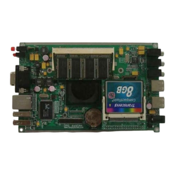
EMB-CPU03
Windows, Windows2000, Windows NT and Windows XP are trademarks of Microsoft. We acknowledge that the
trademarks or service names of all other organizations mentioned in this document as their own property.
Information furnished by DAQ system is believed to be accurate and reliable. However, no responsibility is assumed by DAQ
system for its use, nor for any infringements of patents or other rights of third parties which may result from its use. No license is
granted by implication or otherwise under any patent or copyrights of DAQ system.
The information in this document is subject to change without notice and no part of this document may be copied or
reproduced without the prior written consent.
User's Manual
Copyrights
2009 DAQ system, All rights reserved.
1
-
-
EMB-CPU03 Board User manual
http://www.daqsystem.com
Advertisement

Related Manuals for DAQ system EMB-CPU03


Summary of Contents for DAQ system EMB-CPU03
- Page 1 Information furnished by DAQ system is believed to be accurate and reliable. However, no responsibility is assumed by DAQ system for its use, nor for any infringements of patents or other rights of third parties which may result from its use. No license is granted by implication or otherwise under any patent or copyrights of DAQ system.
- Page 2 EMB-CPU03 Board User manual Contents Introduction Features Specifications Appearance 4.1 Disconnection order 4.2 Windows and Driver Install http://www.daqsystem.com...
-
Page 3: Specifications
EMB-CPU03 Board User manual 1. Introduction It is the low cost Single Board Computer(SBC) which equipped a low power and low heat processor. It provides solution to be suitable for Embeded market wanting low power and small size. - Page 4 EMB-CPU03 Board User manual Physical Dimension • 160 x 100 x 30mm • Front I/O : Power switch, D-sub video connector, 2xUSB, Ethernet, 2xStatus LED • Rear I/O : 2xUSB, Audio/Mic/Speaker, +12V Power • On-Board : LCD output, IDE 4. Appearance...
- Page 5 EMB-CPU03 Board User manual Side 4.1 EMB-CPU03 organization disconnection order(Assembly process reversely disconnection) 1. Right side disconnection – “+” 2 bolts http://www.daqsystem.com...
- Page 6 EMB-CPU03 Board User manual 2. LCD disconnection – LCD Connector disconnect 1-LCD-Back Light 2-Video data main 3-Touch http://www.daqsystem.com...
- Page 7 EMB-CPU03 Board User manual 3. Board fixed bolt disconnection – eight bolts disconnect by 0.9mm hexagonal wrench 4. Assembly and Board Disconnection – board disconnect by push the right http://www.daqsystem.com...
- Page 8 EMB-CPU03 Board User manual 5. RAM /CF Card disconnection – it can use a RAM and HARD DISK according to the user CF Card IDE Pin CF card Socket The H.D.D(hard Disk Drive) is a CF CARD and IDE 1.8inch.
- Page 9 4.2 EMB-CPU03 Board Install WINDOWS and Driver 1. To connect a USB KEYBOARD and USB MOUSE and USB CD-ROM (WINDOWs CD) at EMB-CPU03 Board. And, connect the power(12V, 1.5~3A) after connection to a DSUB 15 PIN VGA PORT and light up the switch.
- Page 10 EMB-CPU03 Board User manual 4. After choose the “USB CD-ROM Drive <- Conflict 4” at 1 line, and press down the “Esc”. 5. After choose the “Save values and Exit”, and escape the display. 6. Booting is performed with a USB CD-ROM, you are able to progress a windows install guide.
- Page 11 EMB-CPU03 Board User manual 8.2 LAN Driver Installation Execute SET-UP file in LAN folder in CD-ROM. 8.3 LCD Driver Installation(DISPLAY) - Choose the DRIVER in LCD folder in CD ROM. (Choose the DRIVER in VGA folder only used VGA.) 8.4 Touch Installation - After execute the Setup file in Touch folder in CD-ROM, display the icon of TouchWare at the wallpaper.
- Page 12 EMB-CPU03 Board User manual After finding the port at Touch Controller, press “OK”. Choose the “Calibrate” button. When show the below display, press the lighting point. (You should continuously press until completed progress bar.) Press “Yes”, and then finished the install.
- Page 13 EMB-CPU03 Board User manual 9. The optimum display set for the LCD. Change the resolution 800x400 because LCD resolution is optimum 800x480. Choose the “Property” in wallpaper. Click the “Advancd” in “Setting” in “Display Registration Information” display. Click the “List All Modes” in “Adaptor”...
Need help?
Do you have a question about the EMB-CPU03 and is the answer not in the manual?
Questions and answers