
Related Manuals for Schmalz SGM-HP


Summary of Contents for Schmalz SGM-HP
- Page 1 Operating instructions Magnetic Gripper SGM-HP / SGM-HT-HP WWW.SCHMALZ.COM EN-US · 30.30.01.01206 · 10 · 07/23...
- Page 2 Published by © J. Schmalz GmbH, 07/23 This document is protected by copyright. J. Schmalz GmbH retains the rights established thereby. Repro- duction of the contents, in full or in part, is only permitted within the limits of the legal provisions of copyright law. Any modifications to or abridgments of the document are prohibited without explicit writ- ten agreement from J. Schmalz GmbH.
-
Page 3: Table Of Contents
Contents Contents 1 Important Information ........................... 5 The technical documentation is part of the product ................ 5 Note on Using this Document...................... 5 Type Plate............................. 5 Symbols.............................. 5 2 Fundamental Safety Instructions........................ 6 Intended Use ............................ 6 Non-Intended Use.......................... 6 Personnel Qualifications........................ - Page 4 Contents 12 Disposing of the Product.......................... 28 13 Notes................................ 29 4 / 30 EN-US · 30.30.01.01206 · 10 · 07/23...
-
Page 5: Important Information
ð Failure to follow the instructions in these Operating instructions may result in injuries! ð Schmalz is not liable for damage or malfunctions that result from failure to heed these instructions. If you still have questions after reading the technical documentation, contact Schmalz Service at: www.schmalz.com/services... -
Page 6: Fundamental Safety Instructions
Do not operate the product in aggressive environments (e.g. ambient air containing solvent fumes). 2.2 Non-Intended Use Schmalz accepts no liability for damage caused by the use of the gripper SGM-SV for purposes other than those described under Intended Use. Use of the gripper SGM-SV for loads that are not specified in the or- der confirmation or that have different physical properties than those specified in the order confirmation shall be considered non-intended use. -
Page 7: Warnings In This Document
2.6 Modifications to the Product Schmalz assumes no liability for consequences of modifications over which it has no control: 1. The product must be operated only in its original condition as delivered. 2. Use only original spare parts from Schmalz. -
Page 8: Product Description
3 Product Description 3 Product Description 3.1 Description of the Function The magnetic gripper powered by compressed air lifts ferromagnetic workpieces using a magnetic force. It is used for handling sheet metal and perforated plates, complex laser-cut workpieces, sheet metal with drill holes and apertures, curved sheet metal and pipes. To control the magnet, the system alternately supplies the two gripper connections with compressed air while venting the non-actuated connection. -
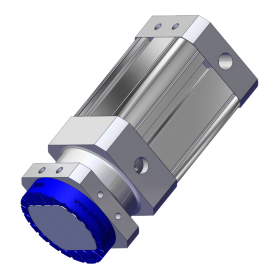
Page 9: Product Design
Friction ring only ...HP, ... HT optional 1/4" mounting thread - central Connection of retaining elements Optional: Proximity sensor (for monitor- ing piston position) only for SGM-HP 1/8" compressed air connection Mechanical connection - lateral (depositing workpiece) 1/8" compressed air connection... -
Page 10: Technical Data
Opt. operating pressure 2.5 to 6.0 bar Operating medium Air or neutral gas, 40 µm filtered, with or without oil, class 7-4-4 com- pressed air quality acc. to ISO 8573-1 Gripper type SGM-HP Type Holding force ≥ 0.5 mm sheet 13 N / 21 N 30 N / 34 N... - Page 11 4 Technical Data Gripper type SGM-HT-HP The friction ring HT2 (black) can be retrofitted as an accessory. Type Holding force ≥ 0.5 mm sheet metal 30 N / 34 N 46 N / 52 N 65 N / 72 N with/without friction ring Holding force ≥ 0.7 mm sheet metal 46 N / 55 N 60 N...
-
Page 12: Dimensions
4 Technical Data 4.2 Dimensions Variant SGM-HP Type SGM-HP 20 20.1 78.2 13.2 1/8" in- ternal thread SGM-HP 30 30.1 99.4 20.5 15.7 1/8" in- ternal thread SGM-HP 40 40.65 99.4 24.2 15.7 1/4" in- ternal thread SGM-HP 50 50.7 123.4 41.5... - Page 13 4 Technical Data Variant SGM-HT-HP Type SGM-HT-HP 30 30.1 99.2 26.9 20.5 15.5 1/8" in- ternal thread SGM-HT-HP 40 40.65 99.2 38.4 24.2 15.5 1/4" in- ternal thread SGM-HT-HP 50 50.7 123.2 48.4 41.5 31.2 15.5 1/4" in- ternal thread Type SGM-HT-HP 30 1/8"...
-
Page 14: Transportation And Storage
1. Compare the entire delivery with the supplied delivery notes to make sure nothing is missing. 2. Damage caused by defective packaging or occurring in transit must be reported immediately to the carrier and J. Schmalz GmbH. 5.2 Reusing the Packaging The product is delivered in cardboard packaging. The packaging should be reused to safely transport the product at a later stage. -
Page 15: Installation
6.2 Mechanical Attachment The gripper is adapted to a handling system either directly or by using interchangeable holder systems. Only the Schmalz holder system (accessories) may be used for the lateral connection. The product can be mounted in any position. The following threads are used to attach the gripper to a holder: (1) 1/4"... -
Page 16: Pneumatic Connection
6 Installation 6.3 Pneumatic connection Lay the hose lines: • as short as possible • without bends and crimps • so that they do not rub CAUTION Getting caught in the hose lines Risk of injury 4 Wear tight clothing when working on or near the robot. 4 Route the hose lines and cables closely along the robot arm without restricting the movement of the robot. -
Page 17: Optional: Sensor For Monitoring The Piston Position Of The Gripper
Observe the minimum distances specified below. • The sensor, sensor slot, and gripper(s) must be regularly inspected and any ferromagnetic pollutants (such as iron shavings) removed. Minimum distances of magnetizable objects Type SGM-HP Direction A/B/C/D A/B/C/D A/B/C/D A/B/C/D Rec. - Page 18 6 Installation 6.4.3 Mounting the Sensor Commissioning the sensor for first-time installation or resetting if necessary 1. Place sensor centrally in the T-slot. 2. Push the sensor to the stop of the T-slot, or in the case of variants with open T-slot, fix the sensor flush with the lower end of the slot (towards the gripping surface).
- Page 19 6 Installation 3 sec 2. Press and hold the Teach button for 3 seconds. ð LED 1 flashes 3. Release the Teach button. ð First switching point is stored (LED 1 lights up and LED 2 flashes) 4. (Put the gripping apparatus/gripper tool in the workpiece depositing position.) Set/actuate the piston position for the second switching point (rear piston in idle state).
- Page 20 6 Installation Inspection of first switching point 1. Move the piston to the position for the first switching point. ð LED 1 illuminated 2. LED 1 not illuminated. ð Check the operating conditions and adjust accordingly. Inspection of second switching point 1. Move the piston to the position for the second switching point. ð...
-
Page 21: Start Of Operations
7 Start of Operations 7 Start of Operations 7.1 Personnel Qualification Unqualified personnel cannot recognize dangers and are therefore exposed to higher risks! 1. Only instruct qualified personnel to perform the tasks described in these operating instructions. 2. The product may only be operated by persons who have undergone appropriate training. 3. -
Page 22: Operation
8 Operation 8 Operation 8.1 Preparations 4 The product must be operated only by persons who have undergone appropriate training. WARNING The product contains a permanent magnet that generates a continuous magnetic field. Danger for persons with pacemakers. Devices and data carriers can be damaged. 4 Keep persons with pacemakers away from the product. -
Page 23: Troubleshooting
9 Troubleshooting 9 Troubleshooting 9.1 Faults, Causes, Solutions Error Cause Solution 4 Check compressed air supply Workpiece is not Magnets are not in the corresponding gripped end position Check hose connections and plug-in screw unions Pressure too low 4 Adhere to the defined temperature Magnetic gripper Sealing elements damaged;... -
Page 24: Maintenance
10 Maintenance 10 Maintenance 10.1 Safety Instructions for Maintenance Maintenance work may only be carried out by qualified mechanics and electricians. Personnel must have read and understood the instructions. WARNING Risk of injury due to incorrect maintenance or troubleshooting 4 Check the proper functioning of the product, especially the safety features, after every maintenance or troubleshooting operation. - Page 25 11 Accessories, Spare Parts and Wearing Parts 11 Accessories, Spare Parts and Wearing Parts Accessories Holder systems Retaining elements ... TRI ... RE Important: Only the Schmalz holder system (acces- sories) may be used for the lateral connection. Designation Part no. Note Friction ring 10.01.17.00410...
- Page 26 11 Accessories, Spare Parts and Wearing Parts Designation Part no. Note Holder system 10.01.17.00567 See Fig. HTS-A2 SGM-HP 30/40 OP Holder system 10.01.17.00557 See Fig. HTS-A3 SGM-HP 30/40 OP Holder system 10.01.17.00563 See Fig. HTS-A5 SGM-HP 30/40 OP Holder system 10.01.17.00651...
- Page 27 11 Accessories, Spare Parts and Wearing Parts Wearing parts Designation Part no. Note Friction ring 10.01.17.00418 For SGM-HP REIB-RING SGM 20 PU-55 Friction ring 10.01.17.00385 For SGM-HP REIB-RING SGM 30 PU-55 Friction ring 10.01.17.00373 For SGM-HP REIB-RING SGM 40 PU-55 Friction ring 10.01.17.00381...
- Page 28 For proper disposal, please contact a company specializing in the disposal of technical goods and instruct the company to observe the applicable disposal and environmental regulations. Schmalz is happy to assist you in finding a suitable company. 28 / 30...
- Page 29 13 Notes 13 Notes EN-US · 30.30.01.01206 · 10 · 07/23 29 / 30...
- Page 30 At Your Service Worldwide Vacuum automation Handling systems WWW.SCHMALZ.COM/AUTOMATION WWW.SCHMALZ.COM/EN-US/VACUUM-LIFTERS- AND-CRANE-SYSTEMS J. Schmalz GmbH Johannes-Schmalz-Str. 1 72293 Glatten, Germany T: +49 (0) 7443 2403-0 schmalz@schmalz.de WWW.SCHMALZ.COM...
Need help?
Do you have a question about the SGM-HP and is the answer not in the manual?
Questions and answers