Schmalz SCPi Operating Instructions Manual
Compact ejector
Hide thumbs
Also See for SCPi:
- Brief operating instructions (68 pages) ,
- Maintenance instructions manual (9 pages)

Related Manuals for Schmalz SCPi


Summary of Contents for Schmalz SCPi
- Page 1 Compact Ejector SCPi / SMPi Operating Instructions WWW.SCHMALZ.COM EN-US · 30.30.01.00078 · 03 · 05/22...
- Page 2 Published by © J. Schmalz GmbH, 05/22 This document is protected by copyright. J. Schmalz GmbH retains the rights established thereby. Repro- duction of the contents, in full or in part, is only permitted within the limits of the legal provisions of copyright law. Any modifications to or abridgments of the document are prohibited without explicit writ- ten agreement from J. Schmalz GmbH.
-
Page 3: Table Of Contents
Contents Contents 1 Important Information ........................... 5 Note on Using this Document ...................... 5 The technical documentation is part of the product ................ 5 Type Plate ............................ 5 Symbol.............................. 6 2 Fundamental Safety Instructions........................ 7 Intended Use............................ 7 Non-Intended Use .......................... 7 Personnel Qualification........................ - Page 4 Contents 6.13 Counters............................. 31 6.14 Displaying the Software Version ...................... 31 6.15 Displaying the serial number...................... 32 6.16 Error messages........................... 32 7 Transport and Storage.......................... 33 Checking the Delivery ........................ 33 Removing the Packaging ........................ 33 8 Installation.............................. 34 Installation Instructions........................ 34 Mounting ............................
-
Page 5: Important Information
ð Failure to follow the instructions in these Operating instructions may result in injuries! ð Schmalz is not liable for damage or malfunctions that result from failure to heed these instructions. If you still have questions after reading the technical documentation, contact Schmalz Service at: www.schmalz.com/services... -
Page 6: Symbol
Important Information 1.4 Symbol This symbol indicates useful and important information. ü This symbol represents a prerequisite that must be met prior to an operational step. 4 This symbol represents an action to be performed. ð This symbol represents the result of an action. Actions that consist of more than one step are numbered: 1. -
Page 7: Fundamental Safety Instructions
Intended use includes observing the technical data and the installation and operating instructions in this manual. 2.2 Non-Intended Use Schmalz accepts no liability for damages caused by non-intended usage of the ejector. In particular, the following are considered non-intended use: •... -
Page 8: Warnings In This Document
Fundamental Safety Instructions 2.4 Warnings in This Document Warnings warn against hazards that may occur when handling the product. This document contains three levels of danger that you can recognize by the signal word. Signal word Meaning WARNING Indicates a medium-risk hazard that could result in death or serious injury if not avoided. -
Page 9: Modifications To The Product
4 Do not look into vacuum openings such as suction lines and hoses. 2.6 Modifications to the Product Schmalz assumes no liability for consequences of modifications over which it has no control: 1. The product must be operated only in its original condition as delivered. -
Page 10: Product Description
Each variant is defined by its item designation. The breakdown of the item designation is as follows: Type of ejector Perfor- Control System monitor- Electrical con- Potential sepa- mance class nection ration SCPi M12-5 without power 1.5 mm Normally Digital vacuum 1xM12, 5-pin Without poten- blow off open... -
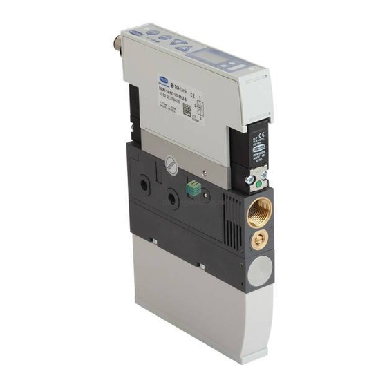
Page 11: Controls And Displays In Detail
Product Description Button for actuating the “blow off” valve 2 x mounting holes manually “Blow off” valve Fastening screw for silencer Operating and display elements — — “Blow off” valve: All ejector variants with NC function (with pilot valve NO) “Suction”... - Page 12 Product Description Vacuum monitoring Item LED color Behavior Vacuum monitoring status Green Lit up Rising vacuum: Vacuum ≥ H1 Falling vacuum: Vacuum ≥ H1-h1 Lit up Rising vacuum < H1 Vacuum < H1 Monitoring functions If switching point H1 is never reached within a suction cycle, the status display remains RED even after the suction cycle has ended.
- Page 13 Product Description Status display overview Suction cycle during which H1 is reached [ctr=on] and no leakage or [ctr=oFF] Air saving function Suction cycle with vacuum control [ctr=on] Suction cycle with vacuum control, during which the valve protection func- tion is triggered [ctr=on] Suction cycle during which H1 is never ex- ceeded...
- Page 14 Product Description H2-h2: Deactivation value of “Part Present” check signal output h2: Hysteresis of “Part Present” check signal output 3.3.2 LED Display for Valves The “suction” and “blow off” process statuses are each assigned an LED. Item Meaning Status Description Blow off LED B Ejector not blowing off Lit up Ejector blowing off...
-
Page 15: Technical Data
Technical Data 4 Technical Data 4.1 Display Parameters Parameter Value Unit Comment Display digit Red 7-segment LED display Resolution ± 2 digit / mbar Unit = mbar Accuracy ± 3 % FS = 25° C, based on FS (full-scale) final value Linearity error ±... -
Page 16: General Parameters
IP65 Operating pressure (flow pressure) Operating medium Air or neutral gas, 5 µm filtered, with or without oil, class 7-4-4 compressed air quality in acc. with ISO 8573-1 4.4 Performance Data Variant SCPi-15 SCPi-20 SCPi-25 SMPi-15 SMPi-20 SMPi-25 Nozzle size 1.5 mm 2.0 mm 2.5 mm... -
Page 17: Dimensions
Technical Data When picked up All values at ambient conditions of T = 20° C and 1000 mbar ambient pressure 4.5 Dimensions 1/4" inter- 3/8" inter- M12x1 ex- M4 inter- 181.5 131.5 71.5 nal thread nal thread ternal nal thread thread or M8x1 ex- ternal thread 87.5... -
Page 18: Factory Settings
Technical Data 4.7 Factory Settings The following table shows the factory settings of the ejector: Code Parameter Value of the factory setting Limit value H1 750 mbar Hysteresis value h1 150 mbar Limit value H2 550 mbar Hysteresis value h2 10 mbar Blow off time 0.2 s Vacuum unit in mbar = -bA Vacuum unit... - Page 19 Technical Data SCPi_NC SMPi_NC SCPi_IMP SMPi_IMP EN-US · 30.30.01.00078 · 03 · 05/22 19 / 54...
-
Page 20: Operating And Menu Concepts
Operating and Menu Concepts 5 Operating and Menu Concepts The ejector is operated using four buttons on the foil keypad: MENU BUTTON UP BUTTON ENTER BUTTON DOWN BUTTON Settings are configured in software menus. The following menus are available: • Main menu: For standard applications •... -
Page 21: Main Menu
Operating and Menu Concepts 5.2 Main Menu All settings for standard applications can be accessed and configured using the main menu. 5.2.1 Functions in the Main Menu The following table shows an overview of the display codes and parameters in the main menu: Display Parameter Explanation... -
Page 22: Configuration Menu
Operating and Menu Concepts 5.3 Configuration Menu The configuration menu is available for applications with special requirements. 5.3.1 Functions in the Configuration Menu The following table shows an overview of the display codes in the configuration menu: Display Parameter Possible settings Explanation code Vacuum unit Define the displayed vacuum unit... -
Page 23: System Menu
Operating and Menu Concepts 5.4 System Menu A special menu is available for reading out system data such as counters, the software version, part num- bers and serial numbers. 5.4.1 Functions in the System Menu The following table shows an overview of the display codes and parameters in the system menu: Display code Parameter Explanation... -
Page 24: General Description Of Functions
General Description of Functions 6 General Description of Functions 6.1 Applying Suction to the Workpiece/Part (Vacuum Generation) The ejector is designed for handling and holding workpieces by means of a vacuum in combination with suction systems. The vacuum is generated in a nozzle according to the venturi principle, using suction generated by the flow of accelerated compressed air. - Page 25 General Description of Functions The operating modes can be set for the control function in the configuration menu under the [ctr] pa- rameter. Operating mode Explanation No control/continuous suction, H1 The ejector produces continuous suction with maximum in hysteresis mode power.
-
Page 26: Depositing The Workpiece/Part (Blowing Off)
General Description of Functions 6.2.2 Overview of the Limit Values The ejector variant with air saving function or control function (RD) is shown. Vacuum Parameter Description Deactivation value of control function Hysteresis of control function H1 - h1 Activation value of control function Activation value of “Part Present”... -
Page 27: Blow Off Functions
General Description of Functions The ejector also has a manual mode. In this mode, the ejector can be controlled using the but- tons on the ejector’s foil keypad. See the “Manual mode” section for more details. 6.4 Blow off Functions This function can be used to choose between two blow off functions. You can set the function using the [blo] parameter in the configuration menu. - Page 28 General Description of Functions 6.6.1 Automatic Operation Once the product is connected to the power supply, it is ready for operation and enters automatic mode. This is the normal operating mode, in which the product is operated by the system control unit. The operating mode may be changed from automatic operation to manual operation using the buttons.
-
Page 29: Vacuum Unit
General Description of Functions In manual mode, a higher level of attention is advisable because incorrect operation may cause gripped parts to fall, resulting in injuries. In manual mode, the “suction” and “blow off” ejector functions can be controlled independently of the higher-level controller using the buttons on the operating panel. -
Page 30: Rotating The Display
General Description of Functions 6.8.2 Output Function The signal output can be switched between [no] (normally open) and [nc] (normally closed) contact. To switch this setting, use the [out] parameter in the configuration menu. The function of the limit value H2 / h2 (“Part Present” check) is assigned to the signal output OUT. 6.9 Rotating the Display To allow different installation positions, the orientation of the display can be rotated by 180°... -
Page 31: Counters
General Description of Functions This function is executed using the re5 parameter in the configuration menu: 1. Press the MENU button for at least three seconds ð When the menu is locked, enter the valid PIN 2. Use the UP or DOWN button to select the menu item rE5 3. -
Page 32: Displaying The Serial Number
General Description of Functions 4. Confirm with the ENTER button ð The value is displayed. 4 To exit the function, press the MENU button 6.15 Displaying the serial number The serial number indicates the production period of the ejector. ü In the system menu, select the 5nr parameter. 1. -
Page 33: Transport And Storage
1. Compare the entire delivery with the supplied delivery notes to make sure nothing is missing. 2. Damage caused by defective packaging or occurring in transit must be reported immediately to the carrier and J. Schmalz GmbH. 7.2 Removing the Packaging The device is delivered packaged in a cardboard box. -
Page 34: Installation
Installation 8 Installation 8.1 Installation Instructions CAUTION Improper installation or maintenance Personal injury or damage to property 4 During installation and maintenance, make sure that the product is disconnected and depressurized and that it cannot be switched on again without authorization. For safe installation, the following instructions must be observed: •... - Page 35 Installation CAUTION Noise pollution due to incorrect installation of the pressure and vacuum connec- tions Hearing damage 4 Correct installation. 4 Wear ear protectors. 8.3.1 Instructions for the Pneumatic Connection To ensure problem-free operation and a long service life for the product, only use adequately maintained compressed air and take the following requirements into account: •...
-
Page 36: Electrical Connection
Installation 4 Connect the compressed air hose. The max. tightening torque is 10 Nm. The 3/8" internal thread vacuum connection is marked with the number 2 on the ejector. 4 Connect the vacuum hose. The max. tighten- ing torque is 10 Nm. 8.4 Electrical Connection WARNING Electric shock... - Page 37 Direct connection to the control of the higher-level machine For example, a Schmalz connection cable can be used to connect the ejector directly to the controller: • Ejector with M12, 5-pin connector: M12-5 connection cable with open end, 5 m, part no.
- Page 38 Gray “Blow off” signal input When Schmalz connection cable part no. 21.04.05.00080 is used Version NO: Suction OFF, version NC: Suction ON, version IMP: Suction ON only Version NO/NC: Blow off ON/OFF, version IMP: Suction OFF and blow off ON/OFF 8.4.3 PIN Assignment of M12, 8-Pin Connection Plug...
-
Page 39: Operation
Operation 9 Operation 9.1 General Preparations WARNING Extraction of hazardous media, liquids or bulk material Personal injury or damage to property! 4 Do not extract harmful media such as dust, oil mists, vapors, aerosols etc. 4 Do not extract aggressive gases or media such as acids, acid fumes, bases, biocides, dis- infectants or detergents. -
Page 40: Help With Faults
No actuator supply voltage spond signment 4 Check the compressed air supply. No compressed air supply 4 Check the ejector and contact Schmalz Ejector is faulty. Service if necessary. Vacuum level is not Press-in screen in contami- 4 Replace screen... -
Page 41: Maintenance
Maintenance 11 Maintenance 11.1 Safety Instructions Maintenance work may only be carried out by qualified personnel. 4 Create atmospheric pressure in the ejector’s compressed air circuit before working on the system! WARNING Failure to follow the instructions in these Operating instructions may result in in- juries! 4 Read the Operating instructions carefully and observe the contents. - Page 42 Maintenance ü A new silencer is available as a replacement 1. Unscrew the fastening screw on the silencer (1) and cover (2) – retain the screw and O-ring (1) for reuse 2. Remove the silencer (3) and cover (2) 3. Attach the new silencer (3) and the cover (2) 4.
-
Page 43: Warranty
Warranty 12 Warranty This system is guaranteed in accordance with our general terms of trade and delivery. The same applies to spare parts, provided that these are original parts supplied by us. We are not liable for any damage resulting from the use of non-original spare parts or accessories. The exclusive use of original spare parts is a prerequisite for the proper functioning of the ejector and for the validity of the warranty. -
Page 44: Spare And Wearing Parts
Spare and Wearing Parts 13 Spare and Wearing Parts Maintenance work may only be carried out by qualified personnel. WARNING Risk of injury due to incorrect maintenance or troubleshooting 4 Check the proper functioning of the product, especially the safety features, after every maintenance or troubleshooting operation. -
Page 45: Accessories
Accessories 14 Accessories Part no. Designation Note 21.04.05.00079 Connection cable M12 socket, 8-pin, 5 m, 8-pin cable, open Max. tightening torque = hand-tight 21.04.05.00080 Connection cable M12, 5-pin, with open end, 5 m Max. tightening torque = hand-tight 10.02.02.00917 Compressed air distributor GP2 Max. -
Page 46: Decommissioning And Recycling
Decommissioning and Recycling 15 Decommissioning and Recycling 15.1 Disposing of the Product 1. Dispose of the product properly after replacement or decommissioning. 2. Observe the country-specific guidelines and legal obligations for waste prevention and disposal. 15.2 Materials Used The table below shows the materials used: Component Material Housing... -
Page 47: Attachment
Attachment 16 Attachment See also 2 SCPi_SMPi IO-Link Data Dictionary 21.10.01.00063_00 2013-01-15.PDF [} 52] 16.1 Overview of the Display Codes Code Parameter Comment Limit value H1 Deactivation value of air saving function/control Hysteresis value h1 Hysteresis of control Limit value H2 Activation value of “Part Present” check signal output (when the output NO is configured) Hysteresis value h2 Hysteresis of “Part Present”... -
Page 48: Ec Conformity
“Clear all” (reset) All values are reset to the factory settings 16.2 EC Conformity EU Conformity Declaration The manufacturer Schmalz confirms that the product Ejector described in these Operating instructions ful- fills the following applicable EU directives: 2014/30/EU Electromagnetic Compatibility 2011/65/EU... -
Page 49: Accessories Design Data
Attachment 16.3 Accessories Design Data 16.3.1 Pressure Connection Plate GP ... Type Number of outputs 49.5 1/2" internal thread All specifications are in mm. EN-US · 30.30.01.00078 · 03 · 05/22 49 / 54... - Page 50 Attachment 16.3.2 Ejector Blanking Plate EJEK-PL … Type EJEK-PL M4 internal thread All specifications are in mm. 16.3.3 Quick Change Connector ADP-Q1 … Number of outputs M5 internal 29.7 43.9 90.5 102.5 49.6 12.1 thread All specifications are in mm. 50 / 54 EN-US ·...
- Page 51 Attachment Mounting the quick change connector 1. Remove the 1/4" latching bolt (14) from the quick change connector G1/4" 2. Coat the 1/4" latching bolt (14) with medium- strength threadlocking adhesive 3. Screw the 1/4" latching bolt (14) into the com- pressed air connector G1 on the ejector.
- Page 52 SPDU Index Data Parameter Value range Access Default value Remark width Identification 0x07 0x00 Vendor ID 2 bytes 0x00EA = 234 = J. Schmalz GmbH 0x08 0xEA 0x09 0x01 0x0A Device ID 3 bytes 0x87 Internal code number 0x0B 0x86 0x0010...
- Page 53 EN-US · 30.30.01.00078 · 03 · 05/22 53 / 54...
Need help?
Do you have a question about the SCPi and is the answer not in the manual?
Questions and answers