Table of Contents
Advertisement
Quick Links
Advertisement
Table of Contents

Related Manuals for Haivision Rack400


Summary of Contents for Haivision Rack400
- Page 1 Rack400 User Guide Document Version: v1.2 Software Version: v2.0...
-
Page 2: Table Of Contents
ONTENTS Copyright and Trademarks..........................1 Compliance............................... 1 Safety and Health Precautions........................2 Operating Environment..........................3 Product Presentation............................. 4 Overview....................................4 Front Panel..................................5 Rear Panel...................................5 Indicators Meaning................................6 Installation................................ 7 Checking Package Content............................7 Installing the Unit................................8 Unit Front Panel..............................9 Menus....................................9 Icons.....................................10 Launching the Web Interface........................11 Ethernet Connection.............................. - Page 3 Conf guration..............................27 Conf guring the Unit Name............................27 Conf guring the Time and Date..........................27 Selecting the Language..............................28 Locating the Unit................................28 Enabling / Disabling Auto-Live at Startup......................29 Enabling / Disabling Screensaver...........................29 Adding and conf guring a Live Prof le.........................30 Deleting a Live Prof le..............................33 Selecting a Live Prof le...............................
- Page 4 Troubleshooting............................. 81 Getting a Report File..............................81 Exporting a Report File from the History Folder..................... 81 Alarm Messages................................82 Specif cations..............................83 Video....................................83 Operations..................................84 Audio....................................84 Video Return................................... 84 Ancilliary Data................................84 Networks................................... 85 Interfaces...................................85 Hardware Specif cations............................. 87 Device disposal............................. 88 Contact Us..............................
-
Page 5: Copyright And Trademarks
Copyright and Trademarks This User Guide and its content are the property of Haivision. It is forbidden to copy, disclose, or reproduce either the whole document or part without Haivision's prior agreement. Compliance Before using the unit, please inform yourself about laws and regulations in force in the country in which you use it. -
Page 6: Safety And Health Precautions
Safety and Health Precautions Handling the Unit • To avoid any injury during the installation, observe local health and safety requirements and guidelines for manual material handling. • The unit must be handled carefully and thoughtfully to prevent safety hazards and damage. Safety Precautions •... -
Page 7: Operating Environment
Furthermore, the unit has a protective earth terminal on the rear side. Caution - Safety precautions Only use the DC adapter and the power cord provided by Haivision. Using another DC adapter and power cord can damage the device and void the warranty. -
Page 8: Product Presentation
IP networks, o9ering a real cost-e9ective alternative to satellite or f ber. The solution is also suitable for installing in vans or trucks, connected to a roof-mounted Haivision Quad CellLink (active 3G/4G multi-antennas) and/or Ka satellite, enabling video broadcast from any place around the globe, even in the midst of unpredictable and unmanaged network conditions. -
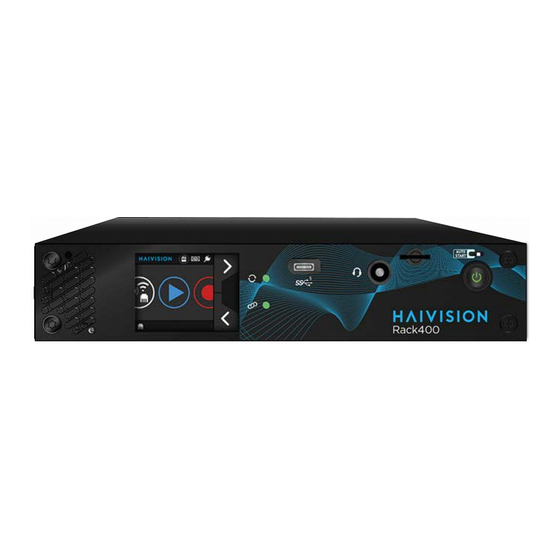
Page 9: Front Panel
Front Panel Micro SD Auto-Start USB C Port Card Slot Touchscreen Switch Activity Indicator Power Button Intercom mini Jack Link Indicator (headphone, micro) Rear Panel DC IN 2 M4 Screw for HDMI 1.4 Genlock 12G-SDI (18V nominal) Protective earth Output Input Output terminal... -
Page 10: Indicators Meaning
Indicators Meaning Activity Indicator Link Indicator Table 1. Activity Indicator Status Meaning Fixed Green The unit is starting. Flashing Green Live, Record or Forward in progress. No Live, Record or Forward in progress. Table 2. Link Indicator Status Meaning Fixed Green The unit is starting or connected to a StreamHub. -
Page 11: Installation
Installation Checking Package Content Please check that the packange contains: • Rack Unit • 18V AC/DC adapter (a second one if ordered) • A printed Quick Start Guide • A f yer with QR code redirecting to Web site with technical documents (User Guide, and Quick Start Guide) •... -
Page 12: Installing The Unit
Installing the Unit 1. Connect the Protective earth terminal. Note: The Protective earth terminal must be connected to the Rack ground pin. This pin must be connected to the safety ground. 2. Connect the AC/DC adapter and the power cable. 3. -
Page 13: Unit Front Panel
Unit Front Panel The unit front panel allows you to: Conf gure the unit • Start / stop live • Start / stop record • Forward stored f les • Menus The diagram below shows the di9erent menus accessible from Home and Settings Menus. Home Menu Forward Stored Conf g. -
Page 14: Icons
Icons On the front panel screen, some icons indicate the unit state. Video Source Video Return Video Return (if enabled) SDI input selected Data Bridge receiving stream Data Bridge Enabled SDI input selected but and Connected no received stream Data Bridge Enabled and not Connected Circles Pattern Selected Bars Pattern Selected... -
Page 15: Launching The Web Interface
Launching the Web Interface The web interface allows you to: Conf gure the unit • Start / stop live • Start / stop record • Forward stored f les • To access the Web interface, use an Ethernet connection. Ethernet Connection 1. -
Page 16: Conf Guring An Ethernet Interface
Conf guring an Ethernet Interface Devices connected to a local LAN transmitter are remotely controllable from the Media Control Room. The unit can operate in di9erent Ethernet modes: DHCP • To use the unit in a domain that has a DHCP server. The DHCP server assigns the IP address, subnet mask and default gateway to the equipment. -
Page 17: From The Web Interface
a. Click on b. Click on settings f elds to be modif ed. c. Use the keyboard to enter new settings and click on to conf rm. d. Click on to scroll down and click on to save new settings. From the Web Interface 1. -
Page 18: Conf Guring A 3G/4G Cellular Interface
Conf guring a 3G/4G Cellular Interface Connecting a Quad CellLink to the Unit Connect a Quad CellLink to the unit to enable cellular networks. 1. Remove the SIM card cover and insert the SIM cards into slots according to indications written on the cover. -
Page 19: Enabling / Disabling A Quad Celllink Cellular Modem
Enabling / Disabling a Quad CellLink Cellular Modem You can enable and disable modems from the Unit Panel or from the Web Interface. From the Unit Panel 1. From the Home menu, click on 2. Click on to select the modem that you want to enable or disable. 3. - Page 20 From the Web Interface 1. From the Web Interface, click on Network > Interfaces. Click on to disable all modems of a Quad CellLink or on to enable them. - 16 -...
-
Page 21: Managing The Apn Database
Managing the APN database Connect a Quad CellLink to the unit to enable cellular networks. See Connecting a Quad CellLink. The unit is delivered with a pre-def ned APN database. You can enrich the database from the Web Interface. You can: Add and conf gure new APN settings to suit your requirements, so they can be easily selected •... - Page 22 From the Unit Panel 1. From the Home menu, click on 2. Click on to select the Modem to conf gure. 3. Click on the line of the modem to be conf gured. 4. Check the APN assigned. a. Click on b.
-
Page 23: Deleting An Apn
If you cannot f nd a relevant APN in the pre-def ned list, you can: • Fill in the APN f elds with proper settings and click on Apply. • Enrich the pre-def ned APN list by adding your APN to it (See Managing the APN database). - Page 24 1. From the Web Interface, click on Network > APN. Note: By default, the APN Automatic Conf guration is enabled. Click on to disable it. The button turns into - 20 -...
-
Page 25: Managing Cellular Operators
Managing Cellular Operators Connect a Quad CellLink to the unit to enable cellular networks. See Connecting a Quad CellLink. For each SIM card, you can decide how to manage the selection of the cellular operator. You have 3 possibilities: Automatic mode: The unit selects the operator by itself. •... -
Page 26: Selecting The Automatic Mode
Selecting the Automatic Mode Note: The Automatic Mode is the default setting. From the Unit Panel 1. From the Home menu, click on 2. Click on to scroll down to the modem to be conf gured. 3. Click on the modem line to enter the MOD. CONFIG menu. 4. -
Page 27: Selecting Manually A Cellular Operator
Note: Only white operators in the list can be selected. 8. Click on to scroll down and click on to save. From the Web Interface 1. Click on the modem line. 2. Select Scan and select in the Selection mode scrolling list. 3. -
Page 28: Conf Guring Modem Bands
Conf guring Modem Bands Note: If modem bands are not set in automatic mode or of they are not all selected, a star is displayed on the modem line. From the Unit Panel Using the Standard mode 1. From the Home menu, click on 2. - Page 29 From the Web Interface Using the Standard mode 1. Click on to conf gure the cellular bands. 2. Click on the Modem tab. 3. Define the Network Mode field and choose • Auto • 4G Only • 3G Only 4. Click on the Preset field and choose •...
-
Page 30: Managing Priorities Of Network Links
Managing Priorities of Network Links You can decide of a priority level (High or Low) for each network link used for Live or Forward operations. These low and high priorities are managed as shown on the diagram below: For Live: •... -
Page 31: Conf Guration
Conf guration The following settings are related to this general menu. Conf guring the Unit Name From the Unit Panel 1. From the Home menu, click on 2. Click on and click on 3. Click on General. 4. Click on the Product Identif er field 5. -
Page 32: Selecting The Language
5. Set the Time and date. Note: The Time and Date format is set to: YYYY-MM-DD HH:MM. From the Web Interface 1. From the Web Interface, click on Settings > General. 2. Click on the Date and/or Time f eld to change it as required. 3. -
Page 33: Enabling / Disabling Auto-Live At Startup
Enabling / Disabling Auto-Live at Startup This option allows you to start a Live automatically once the unit is connected to a StreamHub and once there is a video source. From the Unit Panel 1. From the Home menu, click on 2. -
Page 34: Adding And Conf Guring A Live Prof Le
Adding and conf guring a Live Prof le A Live Prof le is a set of audio and video settings to f t with specif c broadcasting requirements. Live Prof les can be conf gured from either the Web Interface or on the Unit Front Panel. The unit is delivered with 3 default Live Prof les: •... - Page 35 6. Click on to conf rm the new prof le name. 7. Click on to conf gure the Live Prof le settings following the recommendations mentionned in the table above: • Application: Broadcast (SST), Broadcast (SRT) or Broadcast (SST Low Latency) •...
- Page 36 9. Click on Advanced. to enable I and P frames only. 10. Click on Note: I and P frames only is available only if the Encoder Type is H.264. 11. Click on to enable Manual Resolution. The button turns into and the Resolution field appears Note: The Resolution f eld is available only if the Bitrate Control is VBR.
-
Page 37: Deleting A Live Prof Le
Deleting a Live Prof le From the Unit Panel 1. From the Home menu, click on 2. Click on and click on 3. Click on to display the prof le to delete. 4. Long press the prof le to delete. 5. -
Page 38: Adding And Conf Guring A Record Prof Le
Note: • The feature Live + Auto-record is available in Single Encoding mode for HD video source only. • When this option is enabled, a Record starts automatically when a Live is started. • The record prof le used for the Auto-record can be di9erent than the one used for a Record. -
Page 39: Deleting A Record Prof Le
• Video Settings (Encoder Type, Bitrate) When recording, the video is encoded in CBR mode with a resolution as source. • Audio Settings (Encoder Type, Channel Layout, Bitrate) 9. Click on to save the new Record Prof le settings. From the Web Interface 1. -
Page 40: Selecting A Record Prof Le
From the Web Interface 1. Click on Settings > Record. 2. Double click the trash button ( ). Note: To reorder the prof les, drag and drop them. Selecting a Record Prof le You can select di9erent record prof les for: •... - Page 41 3. Activate Auto-forward if required. Note: • When this option is enabled, a Forward starts automatically when a Live is started. • The record prof le used for the Auto-record can be di9erent than the one used for a Record only. - 37 -...
-
Page 42: Adding And Conf Guring A Destination Prof Le
Adding and Conf guring a Destination Prof le A Destination Prof le is a set of parameters allowing the unit to connect to a StreamHub, a Manager or a SRT Receiver. Note: StreamHub is a web-based platform that recieves, decodes, records and distributes video and audio feeds. - Page 43 Note: These settings may have been changed by the system administrator. 8. Click on to save the new Destination Prof le settings. Note: To select the newly created Destination Prof le, see Selecting a Destination Prof From the Web Interface 1.
-
Page 44: Deleting A Destination Prof Le
Deleting a Destination Prof le From the Unit Panel 1. From the Home menu, click on 2. Click on and click on A green dot ( ) indicates the currently selected prof le. 3. Click on to display the prof le to delete. 4. -
Page 45: Conf Guring Aes Encryption
From the Web Interface 1. Click the icon. The encoder current settings are displayed. Select a pre-def ned Destination Prof le. Conf guring AES encryption You can decide to encrypt / scramble a video during a Live operation, provided the destination server's license includes this option. -
Page 46: Conf Guring Forward Settings
3. Click on Advanced. Click on to enable or disable the AES Scrambling function. If enabled, enter the AES key as def ned in the destination server interface (please refer to the Server User Guide). Conf guring Forward Settings The Forward function o9ers three possibilities: •... - Page 47 3. Click on to enable or on to disable the Resume at Startup, Auto-erase, or/ andHot Folder options. Note: • Resume at Startup: If any forward is still in progress when the unit is turned o9, it is resumed when the unit is started up. •...
-
Page 48: Selecting A Mission
Selecting a Mission To receive missions, the selected destination prof le must be a Manager supporting the Story Centric Workf ow. See Selecting a Destination Prof From the Unit Panel 1. Click on to see the di9erent missions. 2. Click on to have more information on the mission. - Page 49 Changing the mission 1. Click on Settings > Missions or on the icon in the top bar. 2. Click on another mission to select it. The icon moves to the selected mission. - 45 -...
-
Page 50: Setting A Video Return
Setting a Video Return The Video Return feature allows Field Units operating on sites to receive live feeds, such as a program currently on air or a teleprompting from the Media Control Room even if a Live is running or not. The unit must be connected to a StreamHub to allow the Video Return feature. -
Page 51: Receiving A Video Return
Receiving a Video Return From the Unit Panel Check that the video return icon appears on the top bar of the screen. If it appears, the unit is receiving a video stream. 1. Connect a screen to the HDMI port of the unit. From the Web Interface The video return icon ( ) on the top bar indicates that the unit is receiving a Video... -
Page 52: Single Encoding Mode
Single Encoding mode Selecting the Video Source You can select amongst: • SDI input • Pattern (Internal Pattern Generator) Note: • When selecting the Pattern generator as a source, you can select the pattern shape amongst color circles, color bars or a black pattern. •... - Page 53 Note: The SYNC input supports SD Black Burst and HD Tri level signals in the following formats: PAL, NTSC, 720p25, 720p29.97, 720p30, 720p50, 720p59.94, 720p60, 1080i50, 1080i59.94, 1080i60, 1080p25, 1080p29.97, 1080p30, 1080p50, 1080p59.94, 1080p60. 7. Click on the Time Code f eld to select SDI input if required. 8.
- Page 54 Note: The SYNC input supports SD Black Burst and HD Tri level signals in the following formats: PAL, NTSC, 720p25, 720p29.97, 720p30, 720p50, 720p59.94, 720p60, 1080i50, 1080i59.94, 1080i60, 1080p25, 1080p29.97, 1080p30, 1080p50, 1080p59.94, 1080p60. 4. In the Time Code f eld, select SDI input (if required). 5.
-
Page 55: Starting A Live
Starting a Live You can start a live manually or you can enable the Auto-live at startup. See chapter Enabling / Disabling Auto-live at Startup. From the Unit Panel 1. From the Home menu, click on The video preview appears on screen and the live prof le selected is reminded. When clicking on , the Live menu reminds some information. - Page 56 Note: See StreamHub User Guide to set another delay during Live operation. In case of a Live and simultaneous Record, another screen appears alternately: Remaining recording Source Standard time possible on SD card Space used on SD Record Duration card Note: To stop the Live: a.
-
Page 57: Starting A Record
Starting a Record Note: Make sure that you inserted a micro SD card before starting a record. This micro SD card must not be in read only (or locked) mode. From the Unit Panel 1. From the Home menu, click on The video preview appears on screen and the record prof le selected is reminded. - Page 58 Amount and Network Bitrate percentage of data already forwarded (if option enabled) Record Duration Note: To stop the Record: a. Click on b. Click on c. Click on to conf rm. To stop the Forward: a. Click on b. Click on c.
-
Page 59: Starting A Forward
Starting a Forward Make sure that a mass storage such as an SD card or a USB memory tick is connected to the unit. You can choose to forward: • The last record • A selection of records • All file From the Unit Panel From the Home menu, click on The forward interface appears:... - Page 60 a. To forward the last record, click on b. To forward some specif c f les, select the f les and click on c. To forward all f les, click on The forward in progress is indicated on the screen. - 56 -...
-
Page 61: Transmitting Files Via The Hot Folder
Transmitting Files via the Hot Folder The Hot Folder function enables you to transmit f les (eg. photos) automatically over unmanaged networks wherever the action is taking place. This function uses an ftp push to transmit f les following the FIFO method (First In, First Out). You can enable or disable the function as required. - Page 62 From the Web Interface 1. Click on Settings > Forward. 2. Click on to enable or disable the Hot Folder function. Once the Hot Folder function is enabled, the icon appears in the upper bar. Files are automatically forwarded following the priority levels def ned on the camera (standard or high priority).
-
Page 63: Multi-Encoding Mode
Multi-Encoding mode With its 4 SDI inputs, the unit can stream up to 4 full HD streams simultaneously. Note: Please note that this feature allows Live only. Set the Multi-Encoding Mode From the Unit Panel 1. From the Home menu, click on 2. -
Page 64: Starting A Live
Starting a Live You can start a live manually or you can enable the Auto-live at startup. See chapter Enabling / Disabling Auto-live at Startup. From the Unit Panel 1. From the Home menu, click on The video preview appears on screen and the live prof le selected is reminded. When clicking on , the Live menu reminds some information for each encoder. - Page 65 Audio bars indicating audio levels Live Duration 4. Click on to display some indications about the Live action: End-to-end Latency Network Bitrate conf gured in the Live Prof le or Source Standard modif ed remotely from StreamHub Live Duration interface Note: See StreamHub User Guide to set another delay during Live operation.
- Page 66 From the Web Interface 1. Click on 2. For each encoder, check that the settings are conf gured and selected as required: • Video Source • Live Prof le • Destination Prof le Note: Please note that all inputs must have the same resolution and the same frame rate.
-
Page 67: Using The Intercom
Using the intercom The Intercom function enables you to communicate with the Master Control Room, using a microphone or a headset connected to the unit. You can manage the Intercom function from the StreamHub interface. Connect the headset, or microphone to the unit. From the StreamHub interface, start the Intercom session (please refer to the StreamHub User Guide). -
Page 68: From The Unit Panel
From the Unit Panel 1. From the Home menu, click on 2. Click on 3. Click on to move to settings Micro and/or Headset levels. 4. Click on to move the cursor. From the Web Interface 1. Click on Settings > I/O. 2. -
Page 69: Conf Guring A Data Bridge
Conf guring a Data Bridge When conf gured in Data Bridge mode, the unit can be used as a Data Bridge that prof des access to Internet from the f eld, or access to devices connected to the transmitter LAN from the studio (such as remote control of camera). -
Page 70: From The Web Interface
From the Web Interface 1. From the Web Interface, click on 2. Select the Destination Prof le from the scrolling list. Click on to enable or disable Data Bridge. Once the Data Bridge is conf gured, the button turns into and an icon appears in the upper bar. -
Page 71: Locking A Field Unit From Manager Interface
Locking a Field Unit from Manager Interface You can lock / unlock a f eld unit from the Manager interface. Please refer to the Manager User Guide to get the procedure to follow. Once the f eld unit is locked, you cannot: add/delete/modify Destination prof les, •... -
Page 72: Using The Remote Control
Using the Remote Control Connect the remote control to the unit thanks to the USB cable. Note: When the Remote control is connected, the Power indicator switch on and the other indicators blink for 3 seconds. Tally Light Live Indicator Record Indicator Power Indicator Activity button... -
Page 73: Indicators Meaning
Indicators Meaning Table 6. Power Indicator Fixed Green The remote control is connected to the unit. The remote control is not connected to the unit. Table 7. Live Indicator Flashing Blue The Live operation is starting. Fixed Blue The Live is in progress. No Live action is running. -
Page 74: Servicing
Servicing Getting the Unit Information From the Unit Panel 1. From the Home menu, click on 2. Click on and click on The Device Info screen appears: 3. Use to scroll down information. From the Web Interface Click the icon to display the unit information: You can access the unit information: •... -
Page 75: Getting The Imei/Imsi/Iccid Numbers
Getting the IMEI/IMSI/ICCID numbers Connect a Quad CellLink to the unit to enable cellular networks. See Connecting a Quad CellLink chapter. • IMEI (International Mobile Equipment Identity) The IMEI number is a unique 15 digit number that identif es a cellular device within a mobile network. -
Page 76: Testing A Live Using The Pattern Mode
Testing a Live using the Pattern Mode Once you have set a Destination Prof le, you can conf gure a Live encoding using a Pattern and test communication between the unit and the destination StreamHub. 1. Click on to access the unit's settings. 2. -
Page 77: Changing The Web Interface Password
Changing the Web Interface Password 1. Click on Admin > Password. 2. Enter the current password. 3. Enter the new password. 4. Conf rm the new password. 5. Click on Apply. Updating the Firmware Note: The Firmware can be updated from the Manager (v3.3.0 and higher) From the Unit Panel Make sure you have uploaded the .fw f rmware f le from the customer portal to an SD card or USB key. - Page 78 From the Web Interface 1. Click on Admin > Update Firmware. 2. Click on the Browse button to select the .fw software f le that you saved. 3. Click on the Update button. 4. Follow the instructions on screen. Note: The update may take several minutes, depending if it is a major update or not.
-
Page 79: Rebooting The Unit
Rebooting the Unit You can reboot the unit from the Web Interface only. 1. Click on Admin > Reboot. 2. Click on Yes to conf rm. Restoring Factory Settings From the Unit Panel 1. From the Home menu, click on 2. -
Page 80: Exporting The Unit Conf Guration
Exporting the Unit Conf guration Click on Backup > Export Conf g. Note: An .awj f le is exported in the download space. This f le can be easily imported later, once factory settings have been restored. Importing the Unit Conf guration From the Unit Panel 1. - Page 81 3. Click on the modem line indicating "Need pin". 4. Click on The screen reminds the number of attempts left to enter the PIN code to unlock the SIM card. 5. Click on OK to activate the keyboard. 6. Enter the PIN code and click on to conf rm.
-
Page 82: Deleting F Le(S) From The Sd Card
Deleting f le(s) from the SD card Note: Make sure that the SD card is not locked. From the Unit Panel 1. From the Home menu, click on 2. Click on and click on 3. Click on Delete. 4. Click on f les you want to delete and click on 5. - Page 83 - 79 -...
-
Page 84: Formatting The Sd Card
Formatting the SD Card Note: This operation can be done only from the Unit Panel 1. From the Home menu, click on 2. Click on and click on 3. Click on Format. 4. Choose between FAT32 or exFAT. 5. Click on Yes to conf rm. 6. -
Page 85: Troubleshooting
Troubleshooting Getting a Report File Haivision's support team may ask for a Report File that you can send by email to help them in investigating about unexpected behaviors. From the Unit Panel 1. From the Home menu, click on 2. Click on and click on 3. -
Page 86: Alarm Messages
Alarm Messages Message Solutions Read-only SD card Unlock the SD card inserted into the unit. Receiver not defined Please see Adding and Configuring a Destination Profile. Bad Video synchronization Check that the video cable(s) are properly connected to the camera and to the •... -
Page 87: Specif Cations
Specif cations Video Standards 3840x2160p 25/29.97/30/50/59.94/60 fps (H.265/HEVC only) 1920x1080p 25/29.97/30/50/59.94/60 fps (H.265/HEVC and H.264/AVC) 1920x1080i 50/59.94/60 fps 1280x720p 50/59.94/60 fps Compression Codec H.265/HEVC H.264/AVC Profile Main High Level Up to 5.1 Up to 4.2 Chroma format 4:2:2 and 4:2:0 4:2:0 Bit depth 8-bit and 10-bit... -
Page 88: Operations
Operations Single Encoder Multi-encoder (x4) Live (only) Record (only) Live + Record in HD only, same video codec for Live and Record Audio Channels Up to 8 channels (SDI input) for the device Codec AAC-LC Bitrate 1 x Mono: 64 kbps - 256 kbps 1 x Stereo: 64 kbps -S S 256 kbps 2 x Mono: 128 kbps - 512 kbps 2 x Stereo: 128 kbps -S S 512kbps... -
Page 89: Networks
Networks Ethernet 2x Links Latency User configurable (end-to-end) Broadcast over SST mode • CBR: 500ms to 10s ◦ VBR: 800ms to 10s ◦ Broadcast low latency mode • CBR: 200ms to 500ms ◦ VBR: not available ◦ Broadcast over SRT mode (Ethernet only) •... - Page 90 Return IFB Channels Intercom Headset Connector type: 4pins (TRRS) 3.5 mm Audio Jack (Signal complies with Apple and Samsung headsets) Pins (Mating plugs) 1: Tip (Left HP) 2: Ring1 (Right HP) 3: Ring2 (Ground) 4: Sleeve (Microphone) Headphone Dynamic Range (20 kHz Filter): 100 dB Headphone THD+N: -70 dB max Headphone Load Impedance: 16 W or higher HeadPhone Output Power: 2 x 55 mW max (16 W)
-
Page 91: Hardware Specif Cations
Hardware Specif cations Power Supply Dual DC input 18 V nominal, 5A Max Power Consumption 34 W max From 25 to 30 W typical Weight 1,36 kg Dimensions 22,2 x 4,4 x 11,5 cm 8.7" x 1.6" x 4.3" Operating temperature -5°C to 40°C 23°F to 104°F 0°C to 40°C for the DC adapter... -
Page 92: Device Disposal
Device disposal Dispose of this product in a separate waste collection facility according to the requirements in force in your country. Please check the regulation in force in your country. In the European Union, please refer to the WEEE Directive. - 88 -... -
Page 93: Contact Us
1 (877) 224-5445 International 1 (514) 334-5445 and choose from the following: Sales - 1, Cloud Services - 3, Support - 4 Managed Services U.S. and International 1 (512) 220-3463 1 (514) 334-0088 Support Portal https://support.haivision.com Product Information info@haivision.com - 89 -...
Need help?
Do you have a question about the Rack400 and is the answer not in the manual?
Questions and answers