
Related Manuals for Regada SP 2-Ex


Summary of Contents for Regada SP 2-Ex
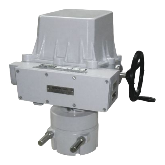
- Page 1 INSTALLATION, SERVICE AND 1026 MAINTENANCE INSTRUCTIONS Explosion-proof electric part-turn actuators SP 2-Ex, SP 2.3-Ex, SP 2.4-Ex ® 74 0868 02 74 0868 02...
- Page 2 TEST CERTIFICATE EXPLOSION-PROOF ELECTRIC PART-TURN ACTUATOR SP 2-Ex, SP 2.3-Ex, SP 2.4-Ex Type number ........... Power supply ..........V .....Hz Serial number ..........Switch-off torque............Nm Production year ..........Operating speed ............s/90° Wiring diagram ..........Operating stroke .............° Warranty period ........months Transmitter...............
-
Page 3: Table Of Contents
Please read these instructions carefully before mounting and operating the actuator! Preventive and safety-measures applied on the actuator can not offer required safety level till the actuator and its safety systems are not applied by required and described way and if installation and maintenance is not applied according to applicable instructions and rules! Contents 1. -
Page 4: General Data
1. General data 1.1 Purpose and applications Explosion - proof electric part-turn actuators (hereinafter EA) types SP 2-Ex, SP 2.3-Ex, SP 2.4-Ex (hereinafter SP X-Ex) resp. EA with controller types are high-powered electric-mechanical products, designed for direct installations onto controlled devices (regulating bodies -valves, etc.). EA are provided for remote control of closing bodies, and EA with controller for automotive control of regulating bodies in both directions of their movement. -
Page 5: Data Specified On Electric Actuator
SP 2-Ex, SP 2.3-Ex, SP 2.4-Ex Design version is : - flameproof enclosures “db“, increased safety “eb” or level dust ignition protection by enclosure “tb” - with explosion protection group IIB or IIIC - and temperature class T5 (max. permissible surface temperature +100°C. -
Page 6: Terminology
SP 2-Ex, SP 2.3-Ex, SP 2.4-Ex Non-explosive label: identifying the manufacturer, certificate number, type identification, version identification, serial number and version for ambient temperature: from -25°C up to +55°C or from -50°C up to +40°C Graphic symbols on electric actuator The graphic symbols used on electric actuator substitute the text messages. -
Page 7: Instructions For Stuff Training
SP 2-Ex, SP 2.3-Ex, SP 2.4-Ex 1.6 Instructions for stuff training Requirements for specialized skills of persons performing assembly, operation and maintenance Electric connection can be performed only by an acquainted person, i.e. an electrical engineer with professional education of electrical engineering at an apprentice school or a technical school (secondary, complete secondary or university education) and whose qualification was verified by an educational facility authorised to verify professional qualification. -
Page 8: Warranty Conditions
SP 2-Ex, SP 2.3-Ex, SP 2.4-Ex 1.8 Warranty conditions The supplier is responsible for completeness of the delivery and guarantees these specifications of the product which are stated in the Contract. The supplier is not responsible for any deterioration of parameters caused by the customer during storage, unauthorised installation or improper operation. - Page 9 SP 2-Ex, SP 2.3-Ex, SP 2.4-Ex • expose to corroding or pollute chemical substances during producing or using of these substances); at places where is handled with small quantity of chemical products and these can accidentally get in contact with an electric device ..............AF 3* •...
-
Page 10: Packing, Transport, Storing And Unpacking
SP 2-Ex, SP 2.3-Ex, SP 2.4-Ex 1.11 Packing, transport, storing and unpacking Surfaces without surface treatment are treated by conservation preparation MOGUL LV 2-3 before packaging . Conservation is not necessary if the following storage conditions are complied with: • Storage temperature: -10 to +50 °C •... -
Page 11: Description, Function And Specifications
SP 2-Ex, SP 2.3-Ex, SP 2.4-Ex 2. Description, function and specifications 2.1 Description and function The SP-Ex EA consist of two parts differing in their function. The gear part is made up by a flange and a connected part for connection onto a controlled device, and gears placed in the bottom;... -
Page 12: Basic Specifications
SP 2-Ex, SP 2.3-Ex, SP 2.4-Ex 2.2 Basic specifications Basic EA specifications: max. load torque [Nm], closing time [s/90°], operation stroke [°], switching-off torque [Nm], and electric motor parameters are given in Table 1. Table 1: Basic specifications Electric motor Switchi Max. - Page 13 SP 2-Ex, SP 2.3-Ex, SP 2.4-Ex For automotive regulation (intermitted operation S4-25%, from 90 up to 1200 cycles per hour) the maximum load torque equals the maximum switching torque multiplied by 0.8 for remote control (short-time operation S2- 10 min, or intermitted operation S4-25%, max. 90 cycles per hour).
- Page 14 SP 2-Ex, SP 2.3-Ex, SP 2.4-Ex Influence of voltage on output current..................0,02%/1V Temperature dependency....................0.5% / 10 °C Output signal values at limit positions: “O“..20 mA (clamps 81; 82) “Z“ ..4 mA (clamps 81; 82) Values tolerance of output signal of capacitive transmitter “Z“..+0,2 mA “O“...
-
Page 15: Installation And Dismantling Of Actuator
SP 2-Ex, SP 2.3-Ex, SP 2.4-Ex • number of controller operation hours • frequency of relay switching in direction "opening" • frequency of relay switching in direction "closing" Supply voltage: ....terminal 61 (L1) -1(N) ............. 230 V AC, ±10% Frequency: ......................... -
Page 16: Electric Connection And Checking Of Function
SP 2-Ex, SP 2.3-Ex, SP 2.4-Ex 3.1.1 Mechanical flange connection • Properly defat contact surfaces of the EA, connecting flange and the valve/gearing. • Coat the valve/gearing output shaft firmly with a grease not containing any acid. • Reset the EA to the limit position "closed"; put the valve to the same limit position. - Page 17 SP 2-Ex, SP 2.3-Ex, SP 2.4-Ex 3. Electronics of the two-wire transmitters is galvanically insulated that is why it can serve as an external source for supplying of several transmitters (their number depends on current which the source can supply).
-
Page 18: Dismantling
SP 2-Ex, SP 2.3-Ex, SP 2.4-Ex Dismantling Before dismantling it is required to disconnect the EA from mains! Do not connect and disconnect live connectors! • Disconnect the EA from mains. • Disconnect the leads from the EA terminal boards and loosen the cables from bushings. Pull out the connectors in case of the connector version. -
Page 19: Adjustment Of Position-Indicating Unit (Fig.3)
SP 2-Ex, SP 2.3-Ex, SP 2.4-Ex 4.2 Adjustment of position-indicating unit (Fig.3) The EA are in the production plant adjusted to a fixed angle (according to the specification), given on the nameplate. While setting, adjusting and resetting follow these steps (Fig. 3): •... -
Page 20: Adjustment Of The Electronic Position Transmitter (Epv) - The Resistive Transmitter (Potentiometer) With The Converter Ptk 1
SP 2-Ex, SP 2.3-Ex, SP 2.4-Ex 4.4 Adjustment of the Electronic Position Transmitter (EPV) - the Resistive Transmitter (Potentiometer) with the Converter PTK 1 4.4.1 EPV – the 2-wire version (Fig. 5) The position transmitter with the converter PTK1 is in the plant adjusted to have the output current signal on the terminals 81-82 as follows: •... -
Page 21: Adjustment Of The Capacitive Transmitter Cpt1/A (Fig.7)
SP 2-Ex, SP 2.3-Ex, SP 2.4-Ex Note: The output signal of (0-20mA, 4-20mA or 0-5mA - according to the specification) can be adjusted at the range from 85 up to 100% of the rated stroke stated on the actuator′s nameplate. At values less than 85% the value of the output signal is reduced proportionally. -
Page 22: Resetting Of Operation Angle And Setting Of Stop End Screws (Fig. 8)
SP 2-Ex, SP 2.3-Ex, SP 2.4-Ex C.) Adjustment of the Capacitive Transmitter Served as a Feedback of the Position Controller While checking or adjusting the output signal of 4÷20 mA follow these steps: • Disconnect the circuit on the terminals 81 and 82 removing the jumper. -
Page 23: Adjustment Of Position Controller (Fig. 9)
Fig.8 4.7 Adjustment of position controller (Fig. 9) The built-in position controller REGADA of new generation is a user-friendly control system to control actuators with an analogue signal. The controller takes advantages of high-power RISC processor MICROCHIP to perform all functions. It provides also continuous automotive diagnostics of the system, error messages as well as number of relay switching and number of controller's operation hours. - Page 24 Adjust the position and torque switches and the position transmitter before adjustment of the controller. Laying of adjusters and signalling elements on the board of the REGADA controller is shown on Fig.9: SW1 button starts an initialisation routine an allows...
- Page 25 SP 2-Ex, SP 2.3-Ex, SP 2.4-Ex "open" and "closed", measures inertia mass in the directions "opening" and "closing", and loads the adjusted parameters into the EEPROM memory. In case that during the initialisation process an error occurs (e.g. in connection or adjustment) the initialisation process will be interrupted and the controller with the D4 diode reports about the type of the error.
-
Page 26: Service, Maintenance And Troubleshooting
SP 2-Ex, SP 2.3-Ex, SP 2.4-Ex 5. Service, maintenance and troubleshooting Service . In general it is provided that service of the EA is performed by a qualified worker in accordance with requirement given in Chapter 1! 2. After putting the EA into operation it is needed to verify whether during manipulation any scratch on surface occurred, it is to be removed to prevent actuator against corrosion! The EA SP-Ex or SP-Ex with controller requires just negligible service. - Page 27 SP 2-Ex, SP 2.3-Ex, SP 2.4-Ex performing of required tests (inclusive of static pressure test of resisting clouser parts) guarantee the fulfil required standardes and rules for this products. The closing surfaces are (Fig.10): • the connecting surface of the upper cover and the lower case (1), •...
-
Page 28: Troubleshooting
SP 2-Ex, SP 2.3-Ex, SP 2.4-Ex 5.4 Troubleshooting • In case of a mains failure the EA stands in the position where it was before the failure occurred. If needed the EA can be reset using the manual control (with the handwheel). When necessary EA... -
Page 29: Enclosures
SP 2-Ex, SP 2.3-Ex, SP 2.4-Ex 7. Enclosures 7.1 Wiring diagrams Wiring diagrams EA SP 2-Ex, SP 2.3-Ex, SP 2.4-Ex... - Page 30 SP 2-Ex, SP 2.3-Ex, SP 2.4-Ex...
- Page 31 SP 2-Ex, SP 2.3-Ex, SP 2.4-Ex Wiring diagrams EA SP 2-Ex, SP 2.3-Ex, SP 2.4-Ex with controller...
- Page 32 SP 2-Ex, SP 2.3-Ex, SP 2.4-Ex...
- Page 33 SP 2-Ex, SP 2.3-Ex, SP 2.4-Ex Legend: Z10b ...wiring diagram of resistive with current converter or capacitive transmitter – 2 - wire without supply Z21....wiring diagram of additional switches for version with controller Z22....wiring diagram of single resistant transmitter Z32....wiring diagram of double resistant transmitter Z249....wiring diagram of EA SP - Ex with controller with resistant feedback –...
-
Page 34: Dimensional Drawings
SP 2-Ex, SP 2.3-Ex, SP 2.4-Ex 7.2 Dimensional drawings Coupling shapes – flange version... - Page 35 SP 2-Ex, SP 2.3-Ex, SP 2.4-Ex Shape D-xx (Axx) Shape L-xx (Bxx) Shape H-xx (Cxx) Shape V-xx (Dxx) D-xx L-xx H-xx V-xx D-14 L-14 H-14 V-20 20,0 22,5 D-17 L-17 H-11 V-22 22,0 24,5 D-22 L-22 V-28 28,0 30,9 D-27...
- Page 36 SP 2-Ex, SP 2.3-Ex, SP 2.4-Ex Coupling shape: Pull-rod TV360:...
- Page 37 SP 2-Ex, SP 2.3-Ex, SP 2.4-Ex...
-
Page 38: List Of Contractual After-Sales Service Centre
Tel.: +421 (0)51 7480 460, Fax: +421 (0)51 7732 096, E-mail: regada@regada.sk Czech Republic: Exclusive representation Regada, s.r.o. (Ltd.) for sale of electric actuators Regada Česká, s.r.o. Nám. 5. května 17, 252 25 Jinočany, PRAHA – západ, Tel.: +420 257 961 302... - Page 39 SP 2-Ex, SP 2.3-Ex, SP 2.4-Ex Notes:...
Need help?
Do you have a question about the SP 2-Ex and is the answer not in the manual?
Questions and answers