
Related Manuals for Regada SPR 0.1PA


Summary of Contents for Regada SPR 0.1PA
- Page 1 INSTALLATION, SERVICE AND MAINTENANCE INSTRUCTIONS Electric part-turn actuators Rematic with the DMS 3 electronic control SPR 0.1PA ® 74 1076 02 74 1076 02...
- Page 2 TEST CERTIFICATE ELECTRIC PART-TURN ACTUATOR SPR 0.1PA Type number 238........ Power supply ......V ..Hz Serial number ........Max. load torque ........Nm Production year ........Operating time ........s/90° Wiring diagram ........Operating angle ..........° ............Input operation signal ........
-
Page 3: Table Of Contents
Please read these instructions carefully before mounting and operating the actuator! Preventive and safety-measures applied on the actuator can not offer required safety level till the actuator and its safety systems are not applied by required and described way and if installation and maintenance is not applied according to applicable instructions and rules! Contents General data..........................2... -
Page 4: General Data
Electric part-turn actuators REMATIC (hereinafter referred as EA only) with the DMS electronic control of the SPR 0.1PA type are set up by the program to be controlled on the 24 V DC voltage level; are set up by the program to be controlled by analogue input signal. -
Page 5: Warning For Safety Use
(circuit breaker, or fuse), which serves at the same time as main switch. EA SPR 0.1PA has own short-circuit protection of motor power supply circuits and space heater. Type of equipment from a connection point of view: The equipment is designed for permanent connection. -
Page 6: Operation Conditions
SPR 0.1PA It is recommended to have after-guarantee service performed by the service department of the production plant, or by a contracted service centre. Serviceman makes the record about service mission after warranty actions and sends it to the production company. - Page 7 SPR 0.1PA (In accordance with IEC 60 364-3:1993) the EA SPR 0.1PA have to resist external effects and operate reliably: In the conditions of the following types of environment: • warm mild to very hot dry with temperature in range -25°C to +55°C ........AA 7* •...
-
Page 8: Description
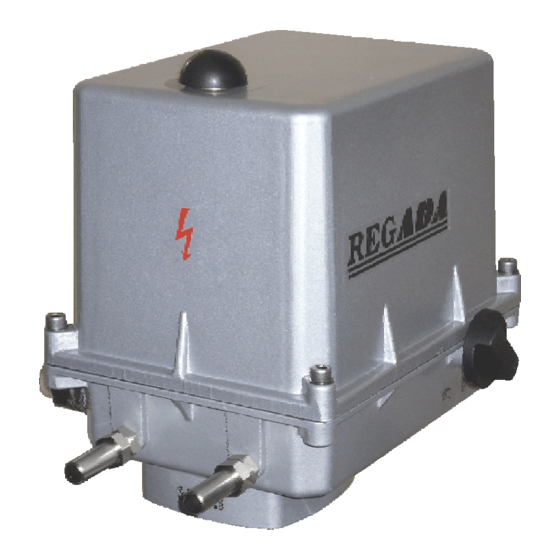
1.8 Description The SPR 0.1PA electric actuator is controlled by 24 V DC voltage fed to the electric actuator’s terminals according to the wiring diagram, resp. by 0/4/12 to 20 mA, 4 to 12 mA (0/2 to 10 V) input control signal and provides for moving the output part of the EA automatically to a position corresponding to the value of the input signal, and other functions as well. - Page 9 SPR 0.1PA Fig. 1...
-
Page 10: Basic Specifications
SPR 0.1PA 1.9 Basic specifications Basic EA specifications: max. load torque [Nm], operating time [s/90°], operating angle [°] and electric motor parameters are given in Table 1. Table 1: Basic EA specifications Electric motor Opera Max. load Max. load Operating... - Page 11 SPR 0.1PA Power supply of electronics: • Power supply ZS is used for single phase versions and feeds the electronic modules built in EA. It provides the 24V DC, 40 mA output voltage. Power sources contain a protective fuse with parameters according to chapter 2.1.2 Electric connection.
- Page 12 Space heater (E1) Space heater - supply voltage: ..........corresponding with motor supply voltage Space heater power output: SPR 0.1PA ..............cca 10 W/55°C Electronic board provides switching of heating element. It is possible to change switching temperatures of the switch from –40°C to +70°C with help of PC and particular software. Factory’s setup for shut down of heating element (thermostat) is +25°C.
- Page 13 SPR 0.1PA Attention: Thermic resistance incoming wires must be minimum +80°C Wire cross-section conversion table (mm – AWG) Wire cross-section 0,05 0,34 0,75 Tightening torque conversion table (N.m – lbs.-in) Tightening torque lbs.-in Cable glands 1 cable gland M20x1,5, diameter of cable 8 to 14,5 mm...
- Page 14 SPR 0.1PA INTERNAL PROTECTION TERMINAL FUSE SUPPLY (F3) Fig. 2 EXTERNAL PROTECTION Fig .2a TERMINAL...
-
Page 15: Packing, Transport, Storing And Unpacking
SPR 0.1PA 1.10 Packing, transport, storing and unpacking The EA SPR 0.1PA are delivered in solid packages guaranteeing resistance in accordance with EN 60 654. Package is a box. Products in boxes is possible to load on the pallets (pallet is returnable). On the outer side of the package is stated: •... -
Page 16: Installation And Dismantling Of Actuator
SPR 0.1PA 2. Installation and dismantling of actuator 2.1 Installation Abide by safety measures! Notes: Repeatedly verify whether placing of EA correspondents to part "Operating conditions". If actual conditions differ from recommended, it is necessary to consult it with manufacturer. - Page 17 SPR 0.1PA Mechanical flange connection • Clean contact surfaces of connecting parts of the EA and valve. • If necessary, connect an additional adapter to the EA or interface adapter (e.g. adapter with a hand lever, which is used also as position indicator and stop end).
-
Page 18: Dismantling
5. Reversation of EA is guaranteed when time interval between switch-on and switch-off the power supply for reverse direction movement of output part is min. 50 ms. With SPR 0.1PA electric actuator, the optimal functioning needs to perform autocalibration as stated in chapter 3.1 during the process of operation. -
Page 19: Adjusting Of Actuator
SPR 0.1PA 3. Adjusting of actuator Attention! See chapter 1.2 2 Requirements for professional qualification … Observe safety regulations! EA are delivered adjusted onto parameters according to type plate from Production plant. The adjustment can be performed at a mechanically and electrically connected EA. This part describes adjustment of EA to specified parameters in case that any unit of EA is reset. - Page 20 SPR 0.1PA SETTING BUTTON P SETTING BUTTON O BUTTON MENU SETTING BUTTON C COMMUNICATION CONNECTOR LED ERROR LED OPEN LED MENU LED CLOSE LED PAR LED I1 LED SEL LED I2 LED POWER Fig. 6...
-
Page 21: Ea Control Set-Up Options (Regulating)
SPR 0.1PA 3.1 EA control set-up options (regulating) 2P CONTROL Setting-up: 2P control + other functions, in addition to STOP on I1 outlet: The EA moves either to the OPEN or CLOSE direction with 24V DC voltage supplied to clamps OPEN or CLOSE. -
Page 22: Procedure For Setting Individual Parameters And The Register Of Errors And Warnings Is Given In The Separate Attachment 74 1053 02 Of These Operating Instructions
SPR 0.1PA 3.2 Procedure for setting individual parameters and the register of errors and warnings is given in the separate attachment 74 1053 02 of these operating instructions. The factory default setting of individual programmes shown in Table 2, as long as otherwise specified by the... -
Page 23: Putting An Ea Into Operation When The Stroke And Parameter Setting Done By The Producer Suit To Your Needs
SPR 0.1PA Warning 1: When the input control signal is set to the value 0 ÷ 20 mA (0-10V), or 20 ÷ 0 mA(10-0V) and the input control signal fails, then the EA keeps the position as with a 0 mA input signal (EA doesn’t recognise between input signal fail and 0 mA (0V) input signal). -
Page 24: Putting An Ea Into Operation When It Is Necessary To Do A Change To The Angle
SPR 0.1PA 3.5 Putting an EA into operation when it is necessary to do a change to the angle (setting new end positions), and the other parameter setting done by the producer suits to your needs When an EA is delivered from the producer without armature, and the setting of other parameters done by the... -
Page 25: Adjusting Of Stop Ends (Fig.8)
SPR 0.1PA 3.8 Adjusting of stop ends (Fig.8) Mechanical stop ends is possible to adjust in scale from –5 °C to 10 °C for each position dependently. Electric actuator is by producer adjusted to operating angle according to the specification. -
Page 26: Maintenance - Extent And Periodicity
SPR 0.1PA Manual control: If needed (during adjusting, function checking, failure etc.) the stuff can change setting of the controlled body using the handwheel. Instructions for manual control: • Switch the power supply off. • Turn the button for gear disengagement to the right by 90° (Fig. 9), the button arrow shows the symbol of hand) what disengages the gear in the actuator. -
Page 27: Troubleshooting
SPR 0.1PA Troubleshooting At failure of power supply the EA stops in the position where it was before the failure. If needed the EA can be set only with the manual control (the handwheel). After restoration of power the EA is prepared for operation. -
Page 28: Accessories And Spare Parts
SPR 0.1PA Module LCD Wrong Command Hand control Wrong Position Unknown type of modules Position Unknown type of modules Moment Unknown type of modules LED Unknown type of modules LCD Unknown type of modules PWR Notes: X – the error or warning flag is activated. -
Page 29: Accessories
SPR 0.1PA 6. Accessories 6.1 Wiring diagrams... - Page 30 20 mA resp. 4 to 20mA and output signal 4 to 20 mA Z515b ..wiring diagram of EA SPR 0.1PA for control ON/OFF Z523b ..wiring diagram of EA SPR 0.1PA for control ON/OFF or for analogue input 0/2 up to 10V and output signal 4 to 20 mA C.........
- Page 31 SPR 0.1PA Terminals: PE, N, L – terminals (0,05-1,5 mm ) of supply (24 V AC resp. 110/120 V AC, resp. 230/240 V AC, 50/60 Hz (according to the specification – voltage and frequency are stated on type plate of EA) 0 V, +24 V –...
-
Page 32: Dimensional Drawings
SPR 0.1PA 6.2 Dimensional drawings... - Page 33 SPR 0.1PA...
- Page 34 SPR 0.1PA...
- Page 35 SPR 0.1PA...
- Page 36 SPR 0.1PA...
- Page 37 SPR 0.1PA...
- Page 38 SPR 0.1PA...
-
Page 39: Guarantee Service Check Report
SPR 0.1PA 6.3 Guarantee service check report Service center:D Date of repair: Guarantee repair no.: User of actuator: Claim applied by: Actuator type number: Actuator production number: Product claim fault: Detected product fault: Used spare parts: Remarks: Issued on a day:... -
Page 40: Post Guarantee Service Check Report
SPR 0.1PA 6.4 Post guarantee service check report Service center: Date of repair: User of actuator: Actuator operating place : Actuator type number: Actuator production number: Detected product fault: Used spare parts: Remarks: Issued on a day: Signature:... -
Page 41: Commercial Representation
080 01 Prešov Tel.: +421 (0)51 7480 460, Fax: +421 (0)51 7732 096, E-mail: regada@regada.sk Czech republic: REGADA Česká s.r.o. (Ltd.) – exclusive representation REGADA, s.r.o. (Ltd.) for sale of electric actuators Regada Česká, s.r.o. Kopaninská 109 252 25 Ořech PRAHA –...
Need help?
Do you have a question about the SPR 0.1PA and is the answer not in the manual?
Questions and answers