
Related Manuals for Regada SP 1


Summary of Contents for Regada SP 1
- Page 1 INSTALLATION, SERVICE AND MAINTENANCE INSTRUCTIONS Electric Part-Turn Actuators SP 1, SP 2, SP 2.3, SP 2.4 SPR 1, SPR 2, SPR 2.3, SPR 2.4 ® 74 0718 07 74 0718 07...
- Page 2 TEST CERTIFICATE ELECTRIC PART-TURN ACTUATOR SP ...... SPR ........Type number ........Power supply ......V ..Hz Serial number ........Max. load torque ........Nm Production year ........Switching-off torque ........Nm Wiring diagram ........Operating time .........s/90° ............Operating angle..........° ............Transmitter ............
-
Page 3: Table Of Contents
Please read these instructions carefully before mounting and operating the actuator! Contents General data ..........................2 1.1 Purpose and applications........................2 1.2 Data specified on electric actuator ......................3 1.3 Warranty conditions ..........................3 1.4 Under-guarantee and after-guarantee service ..................3 1.4.1 Lifetime of actuators........................ -
Page 4: General Data
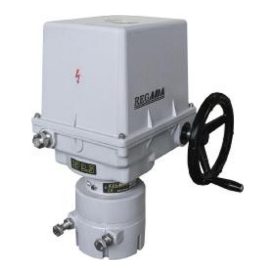
1. General data 1.1 Purpose and applications Electric part-turn actuators (hereinafter EA) of SP 1, SP 2, SP 2.3, SP 2.4 (hereinafter SP) or SPR 1, SPR 2, SPR 2.3, SPR 2.4 (hereinafter SPR) types are high-powered electric-mechanical products designed for direct installations onto controlled devices (regulating bodies - valves, etc.). EA of SP types are provided for remote control of closing bodies, and EA of SPR types for automotive control of regulating bodies in both directions of their movement. -
Page 5: Data Specified On Electric Actuator
SP 1, SP 2, SP 2.3, SP 2.4 SPR1, SPR 2, SPR 2.3, SPR 2.4 Warning for safety use Product protection EA SP(R)1-SP(R)2.4 does not have own short-circuit protection, therefore there must be included suitable protective device into the supply power ( circuit breaker, or fuse), which serves at the same time as main switch. -
Page 6: Lifetime Of Actuators
SP 1, SP 2, SP 2.3, SP 2.4 SPR1, SPR 2, SPR 2.3, SPR 2.4 It is recommended to have after-guarantee service performed by the service department of the production plant, or by a contracted service centre. 1.4.1 Lifetime of actuators The lifetime of an electric actuator (EA) is at least 6 years. - Page 7 SP 1, SP 2, SP 2.3, SP 2.4 SPR1, SPR 2, SPR 2.3, SPR 2.4 - version „marine“ - for climate group World-Wide (WW) / all climate groups except Extremely cold (EC) and Antarctica inland with corrosion resistance C4 (EN ISO 12944-2), with temperatures -50°C to +55°C...
-
Page 8: Power Supply And Duty Cycle
SP 1, SP 2, SP 2.3, SP 2.4 SPR1, SPR 2, SPR 2.3, SPR 2.4 * Marking in accordance with IEC 60 364-3:1993 1.5.3 Power supply and duty cycle Power supply: electric motor..................220/230 V AC, 3x380/3x400 V; 24 V AC / 24 V DC ±10%, 120 V AC±10% (other - after agreement with manufacturer) control ………………………………... -
Page 9: Assessment Of The Product And Packaging And Removal Of Contamination
SP 1, SP 2, SP 2.3, SP 2.4 SPR1, SPR 2, SPR 2.3, SPR 2.4 Upon receiving of EA examine, if during transportation, resp. storing did not come to its damage. At the same time verify, if the data on the labels corresponds to accompanying documentation and purchase-sale contract / order. -
Page 10: Basic Specifications
SP 1, SP 2, SP 2.3, SP 2.4 SPR1, SPR 2, SPR 2.3, SPR 2.4 2.2 Basic specifications Basic EA specifications: Switching-off torque [Nm], Operating time[s/90°], Operating angle [°], and electric motor parameters are given in Table 1. Table 1: Basic Specifications... - Page 11 SP 1, SP 2, SP 2.3, SP 2.4 SPR1, SPR 2, SPR 2.3, SPR 2.4 Electric motor Nominal Switching- off torque Power supply Capacitor ±10 [%] nominal voltage capacity power speed current [s/90°] [°] [Nm] [kg] [1/min] [μF/V] 2750 0,70...
- Page 12 SP 1, SP 2, SP 2.3, SP 2.4 SPR1, SPR 2, SPR 2.3, SPR 2.4 Other specifications: EA protection enclosure: ................IP 65/ IP 67 ((EN (IEC) 60 529)) Mechanical ruggedness: sinusoid vibrations ......with frequency in range from 10 up to 150 Hz, with shift amplitude of 0.15 mm for f<f...
- Page 13 SP 1, SP 2, SP 2.3, SP 2.4 SPR1, SPR 2, SPR 2.3, SPR 2.4 Capacitive transmitter linearity error ..................... ±1,2[%] Capacitive transmitter hysteresis ....................max. 0,6 [%] Electronic positional transmitter (EPV) - converter R/I (B3) a) 2-wire version - without built-in power supply, or with built-in power supply Current signal ........................
-
Page 14: Mechanical Connection
SP 1, SP 2, SP 2.3, SP 2.4 SPR1, SPR 2, SPR 2.3, SPR 2.4 Input control signals - analogue: ....................0 - 20 mA ..............................4 - 20 mA ..............................0 - 10 V Input resistance for signal 0/4 - 20 mA....................250Ω... -
Page 15: Installation And Dismantling Of Actuator
SP 1, SP 2, SP 2.3, SP 2.4 SPR1, SPR 2, SPR 2.3, SPR 2.4 3. Installation and dismantling of actuator Abide by safety measures! Notes: Repeatedly verify whether placing of EA correspondents to part "Operating conditions". If actual conditions differ from recommended, it is necessary to consult it with manufacturer. -
Page 16: Electric Connection And Checking Of Function
SP 1, SP 2, SP 2.3, SP 2.4 SPR1, SPR 2, SPR 2.3, SPR 2.4 Notes: 1. Minimum mechanical ruggedness of screws is 8G. 2. If adjustment of the position-signaling unit, the transmitter or the position indicator in the production plant do not correspond with the EA connected this way, adjust the units. -
Page 17: Dismantling
SP 1, SP 2, SP 2.3, SP 2.4 SPR1, SPR 2, SPR 2.3, SPR 2.4 Notes: 1. The EA are delivered with cable glands, which in case of tight putting on the leads assure protection enclosure up to IP 68. For required protection enclosure it is needed to use rings according to the actual cable diameter. -
Page 18: Adjusting Of Actuator
SP 1, SP 2, SP 2.3, SP 2.4 SPR1, SPR 2, SPR 2.3, SPR 2.4 4. Adjusting of actuator Abide by safety measures! After mechanical connection, electrical connection and checking of connection and function start setting and adjustment of the device. The adjustment can be... -
Page 19: Adjustment Of Resistant Transmitter (Fig.5)
SP 1, SP 2, SP 2.3, SP 2.4 SPR1, SPR 2, SPR 2.3, SPR 2.4 4.3 Adjustment of resistant transmitter (Fig.5) The resistant transmitter is in the EA SP used to function as a remote position indicator; in the EA SPR to function as a feedback in the position controller and if needed also in the position of a remote resistant position indicator. -
Page 20: Epv - 3-Wire Version (Fig. 7)
SP 1, SP 2, SP 2.3, SP 2.4 SPR1, SPR 2, SPR 2.3, SPR 2.4 Note: The output signal of 4-20mA can be adjusted at the range from 75 up to 100% of the rated stroke stated on the actuator′s nameplate. At values less than 75% the value 20mA is reduced proportionally. -
Page 21: Adjustment Of Capacitive Transmitter Cpt1/A
SP 1, SP 2, SP 2.3, SP 2.4 SPR1, SPR 2, SPR 2.3, SPR 2.4 4.5 Adjustment of Capacitive Transmitter CPT1/A The chapter describes adjustment of the capacitive transmitter to the specified parameters (standard values of output signals) in case they are reset. The capacitive transmitter serves as a position transmitter of electric actuators with unified output signal of 4÷20 mA in electric actuators SP, or as a feedback of a position... -
Page 22: Resetting Of Operation Angle And Setting Of Stop End Screws (Fig.9)
SP 1, SP 2, SP 2.3, SP 2.4 SPR1, SPR 2, SPR 2.3, SPR 2.4 • Having the transmitter adjusted put the jumper again on the terminals 81 and 82 in case that the output signal wont be used (the circuit through the terminals 81 and 82 should be closed). -
Page 23: Adjustment Of Position Controller (Fig. 10)
Setting of the controller is performed using buttons and LED diodes. Adjust the position and torque switches and the position transmitter before adjustment of the controller. Laying of adjusters and signaling elements on the board of the REGADA controller is shown on Fig. 10: SW1 button... -
Page 24: Watching Operation And Error States
SP 1, SP 2, SP 2.3, SP 2.4 SPR1, SPR 2, SPR 2.3, SPR 2.4 Table 2: D3 (yellow) diode D4 (red) diode Adjust menu Adjusted parameter number of blinking number of blinking 1 blink 0-20mA 1 blink control signal... -
Page 25: Service, Maintenance And Troubleshooting
SP 1, SP 2, SP 2.3, SP 2.4 SPR1, SPR 2, SPR 2.3, SPR 2.4 b) Error state with the D4 and D3 LED diodes indicating - D4 continuously lighting, D3 indicates error state with blinking 1 blink (repeated) indication of the "TEST" mode - the EA is put to the position according to the signal in the "TEST"... -
Page 26: Maintenance - Extent And Periodicity
SP 1, SP 2, SP 2.3, SP 2.4 SPR1, SPR 2, SPR 2.3, SPR 2.4 5.2 Maintenance - extent and periodicity During inspections and maintenance is needed to tighten all screws and nuts that affect the tightness and coverage. Similarly, once a year should be checked and if necessary tighten mounting screws of the terminal wires and assuring of the slip-on joints with wires. -
Page 27: Accessories And Spare Parts
SP 1, SP 2, SP 2.3, SP 2.4 SPR1, SPR 2, SPR 2.3, SPR 2.4 6. Accessories and spare parts 6.1 Accessories The EA is delivered with the handwheel and cable glands. 6.2 Spare part list Spare part Order Nr. -
Page 28: Enclosures
SP 1, SP 2, SP 2.3, SP 2.4 SPR1, SPR 2, SPR 2.3, SPR 2.4 7. Enclosures 7.1 Wiring diagrams Wiring diagrams electric actuator SP... - Page 29 SP 1, SP 2, SP 2.3, SP 2.4 SPR1, SPR 2, SPR 2.3, SPR 2.4...
- Page 30 SP 1, SP 2, SP 2.3, SP 2.4 SPR1, SPR 2, SPR 2.3, SPR 2.4...
- Page 31 SP 1, SP 2, SP 2.3, SP 2.4 SPR1, SPR 2, SPR 2.3, SPR 2.4 Wiring diagrams electric actuator SPR ERROR ERROR MESSAGE MESSAGE ERROR MESSAGE ERROR MESSAGE ERROR MESSAGE...
- Page 32 SP 1, SP 2, SP 2.3, SP 2.4 SPR1, SPR 2, SPR 2.3, SPR 2.4 ERROR ERROR MESSAGE MESSAGE ERROR ERROR MESSAGE MESSAGE ERROR ERROR MESSAGE MESSAGE ERROR ERROR MESSAGE MESSAGE...
- Page 33 Z505a ....connection of EA SP 2, SP 2.3, SP 2.4 with electric motor 24 V DC and with local control Z505b .....connection of EA SP 1 with electric motor 24 V DC and with local control Z507 ....connection of EA SP1 with electric motor 24 V AC Z507a ....connection of EA SP 2, SP 2.3, SP 2.4 with electric motor 24 V AC...
- Page 34 SP 1, SP 2, SP 2.3, SP 2.4 SPR1, SPR 2, SPR 2.3, SPR 2.4 Z521a ....connection of SPR 1 with controller and resistant feedback for electric motor 24 V AC Z521b ....connection of SPR 2 – SPR 2.4 with controller and resistant feedback for electric motor 24 V AC Z522a ....connection of SPR 1 with controller and current feedback for electric motor 24 V AC...
-
Page 35: Dimensional Drawings
SP 1; SP 2; SP 2.3; SP 2.4 SPR1; SPR 2; SPR 2.3; SPR 2.4 7.2 Dimensional drawings P-1147 Flange ISO 5211... - Page 36 SP 1; SP 2; SP 2.3; SP 2.4 SPR1; SPR 2; SPR 2.3; SPR 2.4 FLANGE DIMENSIONS Flange size SP 1/SPR 1 F07/F05 SP 2/SPR 2 F07/F05 SP 2.3/SPR 2.3 F10/F07 SP 2.4/SPR 2.4 M12 M10 F12/F10 Type SP 1/ SPR 1...
- Page 37 SP 1; SP 2; SP 2.3; SP 2.4 SPR1; SPR 2; SPR 2.3; SPR 2.4 P-1222 EA with electric local control P-1162 Stand + large lever...
- Page 38 SP 1; SP 2; SP 2.3; SP 2.4 SPR1; SPR 2; SPR 2.3; SPR 2.4 P-1225 EA with electric local control DIMENSIONS OF STAND + LARGE LEVER VERSION: Type Drawings 123 233 183 160 13 140 160 10 10,5 330*...
- Page 39 SP 1; SP 2; SP 2.3; SP 2.4 SPR1; SPR 2; SPR 2.3; SPR 2.4 P-0210 Pull-rod TV360 Version Pull-rod version P-1413/A TV 40-1/20 Max.50 Min. 30 P-1413/B TV 50-1/25...
- Page 40 SP 1; SP 2; SP 2.3; SP 2.4 SPR1; SPR 2; SPR 2.3; SPR 2.4 TYPE SP 2.3, SPR 2.3 135 160 194 35 273 532 190 170 120 20 13 60 25 377* 351* SP 2.4, SPR 2.4 200 220...
-
Page 41: Commercial Representation
SP 1; SP 2; SP 2.3; SP 2.4 SPR1; SPR 2; SPR 2.3; SPR 2.4 7.3 Commercial representation Slovak Republic: Regada, s.r.o., Strojnícka 7, 080 01 Prešov Tel.: +421 (0)51 7480 460, Fax: +421 (0)51 7732 096, E-mail: regada@regada.sk...
Need help?
Do you have a question about the SP 1 and is the answer not in the manual?
Questions and answers