
Related Manuals for Regada SP 0


Summary of Contents for Regada SP 0
- Page 1 INSTALLATION, SERVICE AND MAINTENANCE INSTRUCTIONS Electric part-turn actuators SP 0, SPR 0 ® 74 0802 02 74 0802 02...
- Page 2 TEST CERTIFICATE ELECTRIC PART-TURN ACTUATOR SP 0, SPR 0 Type number 280....... Power supply ......V ..Hz Serial number ........Max. load torque ........Nm Production year ........Operating time ........s/90° Wiring diagram ........Operating angle ..........° ............Transmitter............Warranty period ...... months Input operating signal ........
-
Page 3: Table Of Contents
Please read these instructions carefully before mounting and operating the actuator! Preventive and safety-measures applied on the actuator can not offer required safety level till the actuator and its safety systems are not applied by required and described way and if installation and maintenance is not applied according to applicable instructions and rules! Contents General data ........................ -
Page 4: General Data
1. General data 1.1 Purpose and applications Electric part-turn actuators (hereinafter EA) of SP 0 (hereinafter SP) or SPR 0 (hereinafter SPR) types are high-powered electric-mechanical products designed for direct installations onto controlled devices (regulating bodies - valves, etc.). EA of SP types are provided for remote control of closing bodies, and EA of SPR types for automotive control of regulating bodies in both directions of their movement. -
Page 5: Data Specified On Electric Actuator
SP 0, SPR 0 Warning for safety use Product protection EA SP and SPR does not have own short-circuit protection, therefore there must be included suitable protective device into the supply power ( circuit breaker, or fuse), which serves at the same time as main switch. -
Page 6: Operation Conditions
SP 0, SPR 0 It is recommended to have after-guarantee service performed by the service department of the production plant, or by a contracted service centre. 1.5.1 Life of actuators The life of an electric actuator is at least 6 years. - Page 7 SP 0, SPR 0 (In accordance with IEC 60 364-3:1993) the EA SP and SPR have to resist external effects and operate reliably: In the conditions of the following types of environment: • warm mild to very hot dry with temperature in range -25°C to +55°C ........AA 7* in industrial environment: at temperatures stated above •...
-
Page 8: Description And Function
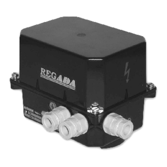
(potentiometer) (8). Plugs for cables (9), an earthling clamp (10) and the disengagement button (11) are located at the actuator sides. The actuators SP 0 can be equipped also with a hand wheel placed on the upper cover. Fig.1 The SPR version is equipped with an electronic controller. - Page 9 SP 0, SPR 0 Table 1: Basic EA specifications Electric motor Nominal Nominal current Operating Operation Max. load torque Power supply time angle 24 V nominal voltage ±10[%] power speed 24 V AC 220/230 V AC [V] ±10% [s/90°] [°]...
- Page 10 SP 0, SPR 0 Position transmitters Resistive – potentiometer: Resistance (single B1):....................100 Ω, 2000 Ω Operating life of transmitter ....................1.10 cycles Load power output:................0.5 W up to 40°C (0 W/125°C) Maximum current of sliding contact ................. max. 35 mA Maximum supply voltage:…………………………………………………..…………..…...
- Page 11 Limit position switches are adjusted with accuracy ± 1°. Additional position switches (S5, S6) are adjusted 15°before end positions. Weight: 1,4 to 2 kg SP 0 –1,4 to 2 kg SPR 0 –1,8 to 2,4 kg - in accordance with version of mechanical connection of EA;...
-
Page 12: Conservation, Packing, Transport, Storing And Unpacking
• To terminal board (X): max. 12 terminals with nominal connecting cable size max. 1.5 mm , max. 2,5 mm (hold for SP 0), or to 12 terminals with nominal connecting cable size max. 1.5 mm , max. 2,5 mm + 5 terminals, connecting cable size max. -
Page 13: Assessment Of The Product And Packaging And Removal Of Contamination
SP 0, SPR 0 Eventual damages to surface finish remove without delay – thus preventing damage by corrosion. If storing takes longer than 1 year, it is necessary to inspect lubrication fillings before putting EA into operation. Assembled EA, but not put into operation is necessary to protect by the equivalent method as during storage (for example suitable protective cover). - Page 14 SP 0, SPR 0 Mechanical connection is available in the following versions: Legend: A ..electric actuator 1 ..screw 2 ..spring washer B ..valve a) With a flange While connection electric actuator with a flange follow these steps (Fig.2): •...
- Page 15 SP 0, SPR 0 Connecting with the master system: The EA can be controlled with: - a built-in position controller - an external position controller 1. If the EA is controlled with an external controller using unified signal from a two- wire transmitter (capacitive or...
-
Page 16: Dismantling
SP 0, SPR 0 The procedure is as follows Press the button SW1 for about 2 sec (i.e. till the D3 diode is got on) to set the controller to the autocalibration mode. During this process the controller checks the feedback transmitter and the sense of turning, puts the EA to the positions open and closed, measures inertia mass in the directions "opening"... -
Page 17: Adjustment Of Resistant Transmitter (Fig.5)
SP 0, SPR 0 3.2 Adjustment of resistant transmitter (Fig.5) The resistant transmitter is in the EA SP used to function as a remote position indicator; in the EA SPR to function as a feedback in the position controller and if needed also in the position of a remote resistant position indicator. -
Page 18: Adjustment Of Position Controller (Fig. 8)
85% the value of the output signal is reduced proportionally. 3.4 Adjustment of position controller (Fig. 8) The built-in position controller REGADA of new generation is a user-friendly control system to control actuators with an analogue signal. The controller takes advantages of high-power RISC processor MICROCHIP to perform all functions. - Page 19 Adjust the position and torque switches and the position transmitter before adjustment of the controller. Laying of adjusters and signalling elements on the board of the REGADA controller is shown on Fig. 8: SW1 button starts an initialisation routine an allows...
- Page 20 SP 0, SPR 0 of the default parameters (usually control signal of 4-20mA) what is shown with 1 blink on the D4 diode. Then the required parameters of the controller can be changed according to Table 2: • press shortly the SW1 button to list the menu shown with the blinking number on the D4 diode.
-
Page 21: Adjusting Of Stop Ends
SP 0, SPR 0 3.5 Adjusting of stop ends Mechanical stop ends is possible to adjust in scale from –5 °C to 10 °C for each position dependently. Electric actuator is by producer adjusted to operating angle according to the specification. -
Page 22: Maintenance - Extent And Periodicity
SP 0, SPR 0 Instructions for manual control: • Switch the power supply off. • Turn the button for gear disengagement to the right by 90° (Fig. 10), the button arrow shows the symbol of hand) what disengages the gear in the actuator. In case of lever actuator it is needed to hold the lever to prevent the device with load against stroke to the end position. -
Page 23: Spare Part List
SP 0, SPR 0 Taking the EA to pieces for repair purposes is allowed only by professionally qualified persons trained in the production plant or by a contracted service centre! 5. Spare part list Spare part Order Nr. Position Figure Electric motor;... -
Page 24: Accessories
SP 0, SPR 0 6. Accessories 6.1 Wiring diagrams Wiring diagrams for EA SP 0 Wiring diagrams for EA SP 0 – 24 V DC... - Page 25 SP 0, SPR 0 Wiring diagrams foe EA SPR with regulator TEST ERROR INDIC MESSAGE ERROR TEST TEST ERROR MESS. INDIC INDIC MESSAGE Legend: Z19..electrical motor connection Z21 ..additional position switches connection Z22 ..single resistant transmitter connection Z23 ..
-
Page 26: Dimensional Drawings
SP 0, SPR 0 6.2 Dimensional drawings * The dimensions are valid for version with convertern and SPR 0 with controller... - Page 27 SP 0, SPR 0...
- Page 28 SP 0, SPR 0...
- Page 29 SP 0, SPR 0...
- Page 30 SP 0, SPR 0...
- Page 31 SP 0, SPR 0 Position indicator Shape A Shape C VERSION FLANGE SHAPE * The dimensions are valid for version with converter...
Need help?
Do you have a question about the SP 0 and is the answer not in the manual?
Questions and answers