
Related Manuals for Regada SP 1-Ex


Summary of Contents for Regada SP 1-Ex
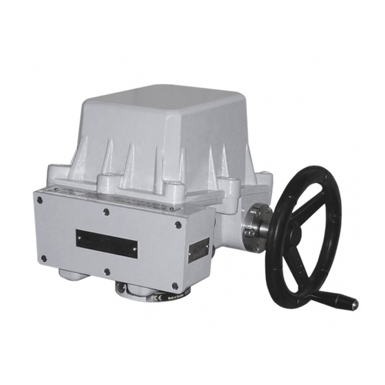
- Page 1 INSTALLATION, SERVICE AND 1026 MAINTENANCE INSTRUCTIONS Explosion-proof electric part-turn actuators SP 1-Ex ® 74 0720 02 74 0720 02...
- Page 2 TEST CERTIFICATE EXPLOSION-PROOF ELECTRIC PART-TURN ACTUATOR SP 1-Ex Type number ........... Power supply ..........V .....Hz Serial number ..........Switch-off torque............Nm Production year ..........Operating time ............s/90° Wiring diagram ..........Operating stroke .............° ............... Transmitter............... Warranty period ........months Input operation signal .............
-
Page 3: Table Of Contents
Please read these instructions carefully before mounting and operating the actuator! Preventive and safety-measures applied on the actuator can not offer required safety level till the actuator and its safety systems are not applied by required and described way and if installation and maintenance is not applied according to applicable instructions and rules! Contents 1. -
Page 4: General Data
1. General data 1.1 Purpose and applications Explosion - proof electric part-turn actuators (hereinafter EA) types SP 1 - Ex resp. SP 1-Ex with controller types are high-powered electric-mechanical products, designed for direct installations onto controlled devices (regulating bodies -valves, etc.). EA are provided for remote control of closing bodies, and EA SP 1-Ex with controller for automotive control of regulating bodies in both directions of their movement. -
Page 5: Data Specified On Electric Actuator
SP 1-Ex Zones for installation of explosion-proof electric actuators and conditions for equipment installation are defined in the following standards: EN/IEC 60079-10: Electrical apparatus for explosive gas atmospheres Part 10: Classification of hazardous areas EN/IEC 60079-14: Electrical apparatus for explosive gas atmospheres... -
Page 6: Terminology
SP 1-Ex Graphic symbols on electric actuator The graphic symbols used on electric actuator substitute the text messages. Some of them are in accordance with EN ISO 7010, ISO 7000 and IEC 60417 within valid edition. Dangerous voltage (EN ISO 7010-W012) -
Page 7: Warning For Safety Use
SP 1-Ex 1.7 Warning for safety use 1. Products are assigned for operation in environment consist of gas, steam and vapours, with temperature range from –25°C up to +55°C; and special version for ultra low temperatures from –50°C up to +40°C, to pressure range from 0.8 to 1.1 bar. EA can be installed at areas specified max. -
Page 8: Under-Guarantee And After-Guarantee Service
SP 1-Ex 1.9 Under-guarantee and after-guarantee service Our customers are provided with professional service of our firm in installation, operation, service, maintenance, revision and help in troubleshooting for all our products. Trained professionals wait for you also in our contracted service centres. - Page 9 1. Duty cycle consist of load type, load factor and switching rate. 2. EA SP 1-Ex is possible connect with an external controller and use this EA as controlled EA, for this EA stands duty cycle and power parameters as for type SP 1-Ex with built-in controller.
-
Page 10: Packing, Transport, Storing And Unpacking
SP 1-Ex 1.11 Packing, transport, storing and unpacking Surfaces without surface treatment are treated by conservation preparation MOGUL LV 2-3 before packaging . Conservation is not necessary if the following storage conditions are complied with: • Storage temperature: -10 to +50 °C •... -
Page 11: Description, Function And Specifications
2. Description, function and specifications 2.1 Description and function The SP 1-Ex EA consist of two parts differing in their function. The gear part is made up by a flange and a connected part for connection onto a controlled device, and gears placed in the bottom; on the other side drive mechanisms for control part units are surfaced. - Page 12 Potentiometer values at limit positions: “O“ (open)..≥ 93%, ”Z“ (closed)..≤ 5% for SP 1-Ex: for SP 1-Ex with controller:“O“ (open)..≥ 85% and ≤ 95%, ”Z“ (closed)..≥3% and ≤ 7% Capacitive (B3): non-contact, life 10 cycles 2-wire connection with power supply or without power supply The current signal 4 ÷...
- Page 13 SP 1-Ex “O“..20 mA (clamps 81; 82) “Z“..4 mA (clamps 81; 82) Values tolerance of output signal of capacitive transmitter “Z“..+0,2 mA “O“ ..±0,1 mA Electronic positional transmitter (EPV) - converter R/I (B3) a) 2-wire version - without built-in power supply Current signal......................
- Page 14 SP 1-Ex •..failure of feedback position transmitter Statistic data: (using RS 232 and personal computer) •..number of controller operation hours •..frequency of relay switching in direction "opening" •..frequency of relay switching in direction "closing" Supply voltage: ....terminal 61 (L1) -1(N) ....230, 24 V AC, ±10% Frequency: .....
-
Page 15: Installation And Dismantling Of Actuator
SP 1-Ex 3. Installation and dismantling of actuator Abide by safety measures! Note: Check again if placement of EA reply to chapter "Operation conditions". In case that operation conditions are different from recommended, consultation with producer is needed. Before starting of mounting the EA onto the valve: Check again whether the EA was not damaged during storing. -
Page 16: Electric Connection And Checking Of Function
SP 1-Ex 3.2 Electric connection and checking of function Follow up with connecting the EA with mains or master system. 1. Follow instructions in the part "Requirements for professional qualification"! 2. While laying electrical line abide by the instructions for heavy current installations. -
Page 17: Dismantling
If it does not correspond change the order of feeding phases (valid for 3x400V version), or change leads of the feeding phase to the corresponding terminals (valid for 230V version). In the SP 1-Ex with controller version with the built-in electronic controller it is needed to perform autocalibration for assuring optimal functioning. Abide by safety measures! -
Page 18: Adjusting Of Actuator
SP 1-Ex 4. Adjusting of actuator Abide by safety measures! After mechanical connection, electrical connection and checking of connection and function start setting and adjustment of the device. The adjustment can be performed at a mechanically and electrically connected EA. This part describes adjustment of EA to specified parameters in case that any unit of EA is reset. -
Page 19: Adjustment Of Resistant Transmitter (Fig. 4)
The resistant transmitter is in the EA SP 1-Ex used to function as a remote position indicator; in the EA SP 1-Ex with controller to function as a feedback in the position controller and if needed also in the position of a remote resistant position indicator. Before the resistant transmitter adjustment the position switches have to be adjusted. -
Page 20: Adjustment Of The Electronic Position Transmitter (Epv) - The Resistive Transmitter (Potentiometer) With The Converter Ptk 1
”open“ ......20 mA • in the position ”closed“ ......4 mA If the transmitter requires a new adjustment follow these steps: Adjustment of the EPV in EA SP 1-Ex: • Put the actuator to the position „closed“ and switch the power supply off. -
Page 21: Adjustment Of The Capacitive Transmitter Cpt1/A (Fig.6)
4÷20 mA in electric actuators SP 1-Ex, or as a feedback of a position controller, or if required it functions also as a remote position transmitter of electric actuators with unified output signal of 4÷20 mA in electric actuators SP 1-Ex with controllers. - Page 22 SP 1-Ex A.) Adjustment of the Capacitive Transmitter without any Power Supply Before connecting check the power supply. The measured voltage should be in range from 18 up to 28 V DC. The voltage of the power supply must not be in any case higher than 30 V DC. The transmitter can be irreversibly damaged While checking or adjusting the output signal of 4÷20 mA follow these steps:...
-
Page 23: Resetting Of Operation Angle And Setting Of Stop End Screws (Fig. 8)
SP 1-Ex 4.6 Resetting of operation angle and setting of stop end screws (Fig. 8) The valve operation angle position is defined with the stop end screws which allow to change the position from the position "Z" (closed - 0°) and from the position "O" (open - 60°, 90°, 120°, 160°) by a value of ±15°. -
Page 24: Adjustment Of Position Controller (Fig. 8)
Adjust the position and torque switches and the position transmitter before adjustment of the controller. Laying of adjusters and signalling elements on the board of the REGADA controller is shown on Fig.8: SW1 button starts an initialisation routine an allows... - Page 25 SP 1-Ex Controller setting procedure: Set the actuator into a mid-position. The initialisation routine starts at the switched-on controller, zero system deviation and short pressing of the SW1 button for ca 2 sec (i.e. until the diode D3 got on). Loosing the button some of the...
-
Page 26: Service, Maintenance And Troubleshooting
2. After putting the EA into operation it is needed to verify whether during manipulation any scratch on surface occurred, it is to be removed to prevent actuator against corrosion! The EA SP 1-Ex requires just negligible service. Proper putting into operation is a recondition of reliable operation. -
Page 27: Troubleshooting
SP 1-Ex Reparation of EA (basically the parts the resisting closures consist with, have substantial influence on safety) is allowed perform only by producer, which according to certificated documentation and by performing of required tests (inclusive of static pressure test of resisting clouser parts) guarantee the fulfil required standardes and rules for this products. -
Page 28: Enclosures
SP 1-Ex 7. Enclosures 7.1 Wiring diagrams Wiring diagrams EA SP 1-Ex... - Page 29 SP 1-Ex Wiring diagrams EA SP 1-Ex with controller ERROR MESSAGE ERROR MESSAGE...
- Page 30 SP 1-Ex...
- Page 31 Z22....wiring diagram of single resistant transmitter connection Z32....wiring diagram of double resistant transmitter Z248....wiring diagram of EA SP 1-Ex with controller with current feedback - 230 V AC Z249a..wiring diagram of EA SP 1-Ex with controller with resistant feedback - 230 V AC Z257d..3-wire version of EPV - without power supply connection...
- Page 32 SP 1-Ex 7. It is not possible to specify any position transmitter as for the combination of the schemes Z397 + Z396 + Z395 (Z398) or Z397a + Z396 + Z395 (Z398)s with 3 – phase electric motor. Wiring diagram Z395 or Z398 must be specified in the order by words.
-
Page 33: Dimensional Drawings
SP 1-Ex 7.2 Dimensional drawings 7.2.1 Dimensional drawings – flange connection Flange... - Page 34 SP 1-Ex Coupling shapes – flange version Shape D-xx Shape L-xx Shape H-xx Shape V-xx H-xx D-xx L-xx V-xx H-14 D-14 L-14 V-20 20,0 22,5 H-11 D-17 L-17 V-17 17,0 19,5 D-16 L-16 H-13 H-10 Stand + large lever...
- Page 35 SP 1-Ex Coupling shape: Pull-rod TV360:...
-
Page 36: List Of Contractual After-Sales Service Centres
080 01 Prešov Tel.: +421 (0)51 7480 460, Fax: +421 (0)51 7732 096, E-mail: regada@regada.sk Czech Republic: Exclusive representation Regada, s.r.o. (Ltd.) for sale of electric actuators Regada Česká, s.r.o. Nám. 5. května 17, 252 25 Jinočany, PRAHA – západ, Tel.: +420 257 961 302...
Need help?
Do you have a question about the SP 1-Ex and is the answer not in the manual?
Questions and answers