
Related Manuals for Regada SP 0.1


Summary of Contents for Regada SP 0.1
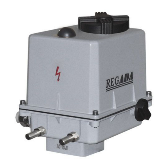
- Page 1 INSTALLATION, SERVICE AND MAINTENANCE INSTRUCTIONS Electric part-turn actuators SP 0.1, SPR 0.1 ® 74 0803 03...
- Page 2 TEST CERTIFICATE ELECTRIC PART-TURN ACTUATOR SP 0.1, SPR 0.1 Type number 331........ Power supply ......V ..Hz Serial number ........Max. load torque ........Nm Production year ........Operating time ........s/90° Wiring diagram ........Operating angle ..........° ............
-
Page 3: Table Of Contents
Please read these instructions carefully before mounting and operating the actuator! Contents General data........................2 1.1 Purpose and applications ....................2 1.2 Safety instructions ......................2 1.3 Data specified on electric actuator.................. 3 1.4 Warranty conditions......................3 1.5 Under-guarantee and after-guarantee service..............3 1.5.1 Life of actuators .................... -
Page 4: General Data
1. General data 1.1 Purpose and applications Electric part-turn actuators (hereinafter EA) of SP 0.1 (hereinafter SP) or SPR 0.1 (hereinafter SPR) types are high-powered electric-mechanical products designed for direct installations onto controlled devices (regulating bodies -valves, etc.). EA of SP types are provided for remote control of closing bodies, and EA of SPR types for automotive control of regulating bodies in both directions of their movement. -
Page 5: Data Specified On Electric Actuator
SP 0.1, SPR 0.1 Warning for safety use Product protection EA SP and SPR does not have own short-circuit protection, therefore there must be included suitable protective device into the supply power ( circuit breaker, or fuse), which serves at the same time as main switch. -
Page 6: Life Of Actuators
SP 0.1, SPR 0.1 1.5.1 Life of actuators The lifetime of an electric actuator (EA) is at least 6 years. EA used for closing mode (closing valves) comply with the requirements for at least 15,000 working cycles (cycle C – O – C: for part-turn EA) -
Page 7: Power Supply And Duty Cycle
SP 0.1, SPR 0.1 Category of location - versions “standard“ and “tropical” are intended for location under the shelter (category 2) Atmosphere type - versions “standard“ and “tropical” are intended for location in atmosphere type II industrial (In accordance with IEC 60 364-3:1993) -
Page 8: Descriptions And Function
SP 0.1, SPR 0.1 Duty cycle (according to EN (IEC) 60034-1.8): EA SP are designed for remote control: • short-time operation S2-10 min • intermitted operation S4-25%, 6 up to 90 cycles per hour EA SPR are designed for automatic regulation: •... -
Page 9: Basic Specifications
SP 0.1, SPR 0.1 1.8 Basic specifications 1.8.1 Basic EA specifications Max. load torque [Nm], closing time [s/90°], operation stroke [°] and electric motor parameters are given in Table 1. Table 1: Basic Specifications Electric motor Nominal Capacitor capacity Operating time... - Page 10 SP 0.1, SPR 0.1 Position transmitters Resistive – potentiometer: Resistance (single B1): ....................100 Ω, 2000 Ω Resistance (double B2): ..................2x100 Ω, 2x2000 Ω Operating life of transmitter..................... 1.10 cycles Load capacity:..................0.5 W up to 40°C (0 W/125°C) Maximum current load:......................
- Page 11 SP 0.1, SPR 0.1 .........................."O“ ±0,1 mA EPV and capacitive transmitter linearity error: ................ ±2 % EPV and capacitive transmitter hysteresis:..............max. 1.5 % from rated value of transmitter referred to output values Electronic position controller (N) Controller software equipment:...
-
Page 12: Mechanical Connection
SP 0.1, SPR 0.1 Supply voltage: ......... corresponding with motor supply voltage (max. 250V AC, 5A) Switching-on temperature: ....................+20°C ± 3 °С Switching-off temperature: ....................+30°C ± 4 °С Manual control: ......................with handwheel; rotating counter-clockwisely (clockwisely) EA output part is moving in direction "Z" ("O") Output part backlash:........... -
Page 13: Assessment Of The Product And Packaging And Removal Of Contamination
SP 0.1, SPR 0.1 Transportation can be executed by heatless and non hermetic spaces of transportation vehicles with influences within the range: - temperature: -25° C up to +70° C (a strange version –45 ° C up to +45 ° C - humidity: 5 up to 100 %, with max. -
Page 14: Installation And Dismantling Of Actuator
SP 0.1, SPR 0.1 2. Installation and dismantling of actuator Abide by safety measures! Notes: Repeatedly verify whether placing of EA correspondents to part "Operating conditions". If actual conditions differ from recommended, it is necessary to consult it with manufacturer. -
Page 15: Electric Connection And Checking Of Function
SP 0.1, SPR 0.1 2.1.2 Electric connection and checking of function 1. Follow instructions in the part "Requirements for professional qualification"! 2. While laying electrical line abide by the instructions for heavy current installations. 3. Cables to terminal boards or connectors lead through cable glands. The cable jacket diameters must conform to the extent specified in Chapter 1.8.3! -
Page 16: Dismantling
SP 0.1, SPR 0.1 The procedure is as follows Press the button SW1 for about 2 sec (i.e. till the D3 diode is got on) to set the controller to the autocalibration mode. During this process the controller checks the feedback transmitter and the sense of turning, puts the EA to the positions open and closed, measures inertia mass in the directions "opening"... -
Page 17: Adjustment Of Position Switches (Version Without Position Transmitter) (Fig.3)
SP 0.1, SPR 0.1 3.2 Adjustment of position switches (version without position transmitter) (Fig.3) While adjusting follow these steps: • Set the actuator to the end position "closed". • Loosen the nuts M1 and M2 locking the cams enough to have the Belleville spring creating the pressure on them. -
Page 18: Adjustment Of The Electronic Position Transmitter (Epv) - The Resistive Transmitter
SP 0.1, SPR 0.1 3.4 Adjustment of the Electronic Position Transmitter (EPV) - the Resistive Transmitter (Potentiometer) with the Converter PTK 1 3.4.1 EPV – the 2-wire version (Fig. 4) The position transmitter with the converter PTK1 is in the plant adjusted to have the output current signal on the terminals 81-82 as follows: •... -
Page 19: Epv - 3-Wire Version (Fig. 5)
4÷20 mA in electric actuators SP 0.1, or as a feedback of a position controller, or if required it functions also as a remote position transmitter of electric actuators with unified output signal of 4÷20 mA in electric actuators SP 0.1 with controllers. -
Page 20: Adjustment Of Pointer
SP 0.1, SPR 0.1 While checking or adjusting the output signal of 4÷20 mA follow these steps: • Connect a mA meter of precision class 0,5 and loading resistance lower than 500 Ω serially with the transmitter (pole „-„; terminal 82) •... -
Page 21: Adjustment Of Position Controller (Fig. 8)
Adjust the position and torque switches and the position transmitter before adjustment of the controller. Laying of adjusters and signalling elements on the board of the REGADA controller is shown on Fig. 8: SW1 button starts an initialisation routine an allows... -
Page 22: Watching Operation And Error States
SP 0.1, SPR 0.1 Notes: The controller at autocalibration automatically sets the feedback type - resistant/current (*) Parameters set in the production plant, if customer has not stated else. (**) Input signal 4 mA - position "closed" 20 mA - position "open"... -
Page 23: Adjusting Of Stop Ends
SP 0.1, SPR 0.1 3.8 Adjusting of stop ends Mechanical stop ends is possible to adjust in scale from –5 °C to 10 °C for each position dependently. Electric actuator is by producer adjusted to operating angle according to the specification. -
Page 24: Maintenance - Extent And Periodicity
SP 0.1, SPR 0.1 Manual control: If needed (during adjusting, function checking, failure etc.) the stuff can change setting of the controlled body using the handwheel. Instructions for manual control: • Switch the power supply off. • Turn the button for gear disengagement to the right by 90° (Fig. 10), the button arrow shows the symbol of hand) what disengages the gear in the actuator. -
Page 25: Troubleshooting
SP 0.1, SPR 0.1 • While connecting and disconnecting of the EA check the tightness of cable glands – those with damaged sealings should be replaced by new ones of the approved type! • Keep the EA clean and take care about removing impurities and dust. The cleaning has to be performed regularly according to the operation possibilities and requirements. -
Page 26: Enclosures
SP 0.1, SPR 0.1 6. Enclosures 6.1 Wiring diagrams Wiring diagrams for EA SP 0.1... - Page 27 SP 0.1, SPR 0.1 Wiring diagrams for EA SPR 0.1 ERROR TEST TEST ERROR MESSAGE INDIC. INDIC. MESSAGE Legend: diagram Z5a ..wiring of single resistant transmitter wiring Z6a ..diagram of double resistant transmitter wiring Z10a ..diagram of resistive with current converter or capacitive transmitter - 2-wire without supply, Z19a ..electrical motor connection with additional position switches...
- Page 28 SP 0.1, SPR 0.1 MS ..synchronous electric motor S4 ..positional switch "closed" N... controller S5 ..additional positional switch "open" R ..resistor S6 ..additional positional switch "closed" ..loop resistance (load resistance) X ..terminal board S3 ..
-
Page 29: Dimensional Drawings
SP 0.1, SPR 0.1 6.2 Dimensional drawings... - Page 30 SP 0.1, SPR 0.1...
- Page 31 SP 0.1, SPR 0.1...
- Page 32 SP 0.1, SPR 0.1...
- Page 33 SP 0.1, SPR 0.1...
- Page 34 SP 0.1, SPR 0.1...
- Page 35 SP 0.1, SPR 0.1...
Need help?
Do you have a question about the SP 0.1 and is the answer not in the manual?
Questions and answers
Здравствуйте! Подскажите Как настроить нулевое положение заслонки на электроприводе 23S 1-DJFF3\AB Привод на 90 градусов и светодиодной индикацией положения от 0 до 100 Спасибо за ответ