
Related Manuals for Regada ST 1-Ex


Summary of Contents for Regada ST 1-Ex
- Page 1 INSTALLATION, SERVICE AND 1026 MAINTENANCE INSTRUCTIONS Explosion-proof electric linear thrust actuators ST 1-Ex ® 74 0724 07...
- Page 2 TEST CERTIFICATE EXPLOSION-PROOF ELECTRIC LINEAR THRUST ACTUATOR ST 1-Ex Type number 411..........Power supply ..........V .....Hz Serial number ..........Set switch-off thrust ............N Production year ..........Operating speed ..........mm/min Wiring diagram ..........Operating stroke ............mm ............... Transmitter...............
-
Page 3: Table Of Contents
Please read these instructions carefully before mounting and operating the actuator! Contents General data ..............................2 Purpose and applications ..........................2 Safety instructions ............................2 Product influence to environment........................2 Data specified on electric actuator ......................3 Terminology..............................4 Instructions for stuff training ........................5 Warning for safety use ..........................5 Warranty conditions.............................5 Under-guarantee and after-guarantee service ....................5 1.10 Operation conditions ...........................6... -
Page 4: General Data
(regulating bodies -valves, etc.). EA of ST 1-Ex types are provided for remote control of closing bodies, and EA with controller for automotive control of regulating bodies in both directions of their movement. They can be equipped with means of measuring and control of technological processes where an unified analogue direct current or voltage signal is an information bearer on their input and/or output. -
Page 5: Data Specified On Electric Actuator
ST 1-Ex Design version is : - flameproof enclosures “d“, increased safety “e” or level dust ignition protection by enclosure “tb” - with explosion protection group IIB or IIIC - and temperature class T6 (max. permissible surface temperature +85°C. Zones for installation of explosion-proof electric actuators and conditions for equipment installation are defined in... -
Page 6: Terminology
ST 1-Ex Non-explosive label: identifying the manufacturer, certificate number, type identification, version identification, serial number and version for ambient temperature: from -25°C up to +55°C or from -50°C up to +40°C or –from 50°C up to +55°C or from -60°C up to +40°C Graphic symbols on electric actuator The graphic symbols used on electric actuator substitute the text messages. -
Page 7: Instructions For Stuff Training
ST 1-Ex 1.6 Instructions for stuff training Requirements for specialized skills of persons performing assembly, operation and maintenance Electric connection can be performed only by an acquainted person, i.e. an electrical engineer with professional education of electrical engineering at an apprentice school or a technical school (secondary, complete secondary or university education) and whose qualification was verified by an educational facility authorised to verify professional qualification. -
Page 8: Operation Conditions
ST 1-Ex Under-guarantee service is performed by the service department of the production plant, or by a contracted service centre according to a written claim. In case of occurring of any fault please let us know it and state: •... -
Page 9: Packing, Transport, Storing And Unpacking
1. Duty cycle consist of load type, load factor and switching rate. 2. EA ST 1-Ex is possible connect with an external controller and use this EA as controlled EA, for this EA stands duty cycle and power parameters as for type ST 1-Ex with built-in controller. For EA with controller we do not suggest operating speed 63 and 80 mm per min. -
Page 10: Appreciation Of The Product And Packing
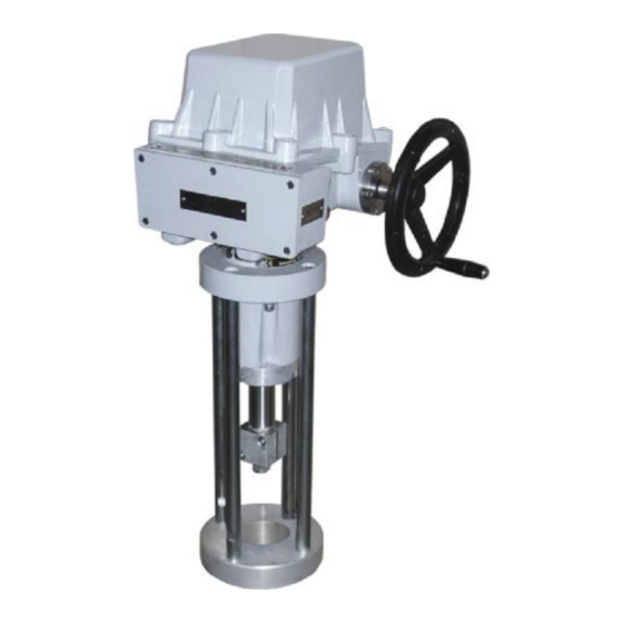
2.1 Description and function The explosion-proof ST 1-Ex, ST 1-Ex with controller electric actuators consist of three parts differing in their function. The gear part is placed in the bottom and covered with a board (2)(Fig.3) where the control part is located. -
Page 11: Basic Specifications
ST 1-Ex 2.2 Basic specifications Basic EA specifications: switching-off thrust [N], operating speed [mm/min], operating stroke [mm], max. load thrust (valid for ST 1-Ex with controller) [N] and electric motor parameters are given in Table 1. Table 1: Basic specifications Max. - Page 12 Potentiometer values at limit positions: “O“ (open)..≥ 93%, ”Z“ (closed)..≤ 5% for ST 1-Ex: “O“ (open)..≥ 85%, ”Z“ (closed)..≤ 5% for ST 1-Ex with controller: Capacitive (B3): non-contact, life 10 cycles 2-wire connection with power supply or without power supply The current signal 4 ÷...
- Page 13 ST 1-Ex EPV and capacitive transmitter linearity error ................... ±1,5[%] EPV and capacitive transmitter hysteresis ..................max. 1,5 [%] 1) from rated value of transmitter referred to output values Electronic position controller (N) Controller software equipment: A) Function and parameters programmable functions: •...
-
Page 14: Installation And Dismantling Of Actuator
ST 1-Ex Mechanical connection: Basic and connecting dimensions are given in dimensional drawings. Electric connection with terminal board (X): - max. 12 terminals – connecting cable size from 0,5 to 2,5 mm - 2 cable bushings – cable diameter from 9 to 13 mm... -
Page 15: Electric Connection And Checking Of Function
ST 1-Ex 3.1.2 Mechanical connection for pillar versions with flanges of A, B, C and D types • Set the actuator (A) and the valve (B) to the position ”closed“. • Loosen and unscrew two screws (5) on the actuator shaft (3) and disconnect the coupling clamping parts (8) •... - Page 16 ST 1-Ex Connecting with the master system: The EA can be controlled with: • a built-in position controller • an external position controller 1. If the EA is controlled with an external controller using unified signal from a two- wire transmitter...
-
Page 17: Dismantling
ST 1-Ex In the ST 1-Ex version with the built-in electronic controller it is needed to perform autocalibration for assuring optimal functioning. The procedure is as follows Press the button SW1 for about 2 sec (i.e. till the D3 diode is got on) to set the controller to the autocalibration mode. -
Page 18: Gear Unit Adjustment
EA ST 1-Ex, or 3 up to 5% of the nominal transmitter resistance in case of EA ST 1-Ex with controller, or in case of EA ST 1-Ex with EPV, i.e. with the resistant transmitter with the converter PTK1 •... -
Page 19: Adjustment Of The Electronic Position Transmitter (Epv) - The Resistive Transmitter (Potentiometer) With The Converter Ptk 1
The output signal of 4-20mA can be adjusted at the range from 75 up to 100% of the rated stroke stated on the actuator′s nameplate. At values less than 75% the value 20mA is reduced proportionally. Adjustment of the EPV in EA ST 1-Ex with controller •... -
Page 20: Adjustment Of The Capacitive Transmitter Cpt1/A (Fig.8)
The capacitive transmitter serves as a position transmitter of electric actuators with unified output signal of 4÷20 mA in electric actuators ST 1-Ex, or as a feedback of a position controller, or if required it functions also as a remote position transmitter of electric actuators with unified output signal of 4÷20 mA in electric actuators ST 1-Ex with controllers. -
Page 21: Adjustment Of Position Controller (Fig. 9)
4.6 Adjustment of position controller (Fig. 9) The built-in position controller REGADA of new generation is a user-friendly control system to control actuators with an analogue signal. The controller takes advantages of high-power RISC processor MICROCHIP to perform all functions. - Page 22 Setting of the controller is performed using buttons and LED diodes. Adjust the position and thrust switches and the position transmitter before adjustment of the controller. Laying of adjusters and signalling elements on the board of the REGADA controller is shown on Fig.9: SW1 button...
-
Page 23: Service, Maintenance And Troubleshooting
2. After putting the EA into operation it is needed to verify whether during manipulation any scratch on surface occurred, it is to be removed to prevent actuator against corrosion! The EA ST 1-Ex or ST 1-Ex with controller requires just negligible service. Proper putting into operation is a recondition of reliable operation. -
Page 24: Maintenance To Assure Inexplosiveness
ST 1-Ex in versions for climate with temperatures -50°C till +40°C grease ISOFLEX TOPAS AK 50. in versions for climate with temperatures -60°C till +40°C grease DISCOR R EP - 000 • - linear adapter – grease GLEIT- µ - HP 520M (to –25°C) resp. HP 520S (to –40°C). -
Page 25: Troubleshooting
ST 1-Ex 5.4 Troubleshooting At failure of power supply the EA stops in the position where it was before the failure. If needed the EA can be set only with the manual control (the hand wheel). After restoration of power the EA is prepared for operation. -
Page 26: Enclosures
ST 1-Ex 7. Enclosures 7.1 Wiring diagrams Wiring diagrams EA ST 1-Ex... - Page 27 ST 1-Ex Wiring diagrams EA ST 1-Ex with controller ERROR MESSAGE ERROR MESSAGE...
- Page 28 ST 1-Ex...
- Page 29 Z22....wiring diagram of single resistant transmitter connection Z32....wiring diagram of double resistant transmitter Z248....wiring diagram of EA ST 1-Ex with controller with current feedback - 230 V AC Z249a..wiring diagram of EA ST 1-Ex with controller with resistant feedback - 230 V AC Z257d..3-wire version of EPV - without power supply connection...
-
Page 30: Dimensional Drawings
ST 1-Ex 7.2 Dimensional drawings Flange ISO 5210 Pillars... -
Page 31: List Of Contractual After-Sales Service Centres
ST 1-Ex 7.3 List of contractual after-sales service centres Regada, s.r.o. Strojnícka 7 080 01 Prešov Slovak Republic Tel.: +421 51 7480 460 Fax: +421 517732 096 E-mail: regada@regada.sk www.regada.sk...
Need help?
Do you have a question about the ST 1-Ex and is the answer not in the manual?
Questions and answers