
Related Manuals for Regada SP 3


Summary of Contents for Regada SP 3
- Page 1 INSTALLATION, SERVICE AND MAINTENANCE INSTRUCTIONS Electric Part-Turn Actuators SP(R) 3, SP(R) 3.4, SP(R) 3.5 ® 74 0945 02 74 0945 02...
- Page 2 TEST CERTIFICATE ELECTRIC PART-TURN ACTUATOR SP ....... SPR ........Type number ........Power supply ......V ..Hz Serial number ........Switching-off torque ........Nm Production year ........Max. load torque ........Nm Wiring diagram ........Operating time ......... s/90° ............Operating angle..........° ............
-
Page 3: Table Of Contents
Please read these instructions carefully before mounting and operating the actuator! Contents General data........................2 1.1 Purpose and applications ....................2 1.2 Safety instructions ......................2 1.3 Data specified on electric actuator.................. 3 1.4 Warranty conditions......................3 1.5 Under-guarantee and after-guarantee service..............3 1.6 Operation conditions....................... -
Page 4: General Data
1. General data 1.1 Purpose and applications Electric part-turn actuators (hereinafter EA) of SP 3, SP 3.4, SP 3.5 (hereinafter SP) or SPR 3, SPR 3.4, SPR 3.5 with controller (hereinafter SPR) types are high-powered electric-mechanical products designed for direct installations onto controlled devices (regulating bodies -valves, etc.). EA of SP types are provided for remote control of closing bodies, and EA of SPR types for automotive control of regulating bodies in both directions of their movement. -
Page 5: Data Specified On Electric Actuator
SP(R) 3, SP(R) 3.4, SP(R) 3.5 Instructions for stuff training Service can be performed only by workers professionally qualified and trained by the producer or contracted service centre. Warning for safety use Product protection EA SP and SPR does not have own short-circuit protection, therefore there must be included suitable protective device into the supply power ( circuit breaker, or fuse), which serves at the same time as main switch. -
Page 6: Operation Conditions
SP(R) 3, SP(R) 3.4, SP(R) 3.5 It is recommended to have after-guarantee service performed by the service department of the production plant, or by a contracted service centre. 1.5.1 Lifetime of actuators The lifetime of an electric actuator (EA) is at least 6 years. EA used for closing mode (closing valves) comply with the requirements for at least 15,000 working cycles (cycle C –... - Page 7 SP(R) 3, SP(R) 3.4, SP(R) 3.5 • with shallow dive – (product in protection IP x 7) ..............AD 7* • with strong dustiness – with a possibility of influences of inflammable, non-conducted and non- explosive dust; the middle layer of dust; the dust drop more than 350 but not more than 1000 mg/m per day (products with protection enclosure of IP 6x) ...........
-
Page 8: Description And Function
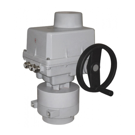
SP(R) 3, SP(R) 3.4, SP(R) 3.5 Description and function The SP and SPR EA consist of two parts differing in their function. The gear part (Fig.1) is made up by a flange (1) and a connected part (2) for connection onto a controlled device, and gears (3) placed in the bottom (4) and electric motor (5) ;... - Page 9 SP(R) 3, SP(R) 3.4, SP(R) 3.5 [Fig.2] Additional accessories: Manual control: made up by a handwheel with a worm gearing (7) – (Fig.1) Local electric control module (Fig.15). In addition, the EA SPR has also an electronic position controller installed. The position controller allows automatic position adjustment of the EA output part depending upon the input signal value and provides also additional functions.
-
Page 10: Basic Specifications
SP(R) 3, SP(R) 3.4, SP(R) 3.5 1.8 Basic specifications Basic EA specifications: Max. load torque [Nm], closing time [s/90°], operation angle [°],switching-off torque [Nm] and electric motor parameters are given in Table 1. Electric motor Closing Max. load Max. load Switching- Nominal Operation... - Page 11 SP(R) 3, SP(R) 3.4, SP(R) 3.5 Other specifications: EA protection enclosure: ……………………………………………………………….. IP 67 (EN/IEC 60 529) Mechanical ruggedness: sinusoid vibrations ..with frequency in range from 10 up to 150 Hz, with shift amplitude of 0.15 mm for f<f with acceleration amplitude of 19.6 m/s for f>f (transition frequency f...
- Page 12 SP(R) 3, SP(R) 3.4, SP(R) 3.5 Output signal values at limit positions: .........."O“..20 mA (clamps 81,82) ............"Z“..4 mA (clamps 81,82) Values tolerance of output signal of capacitive transmitter .........."Z“ +0,2 mA .........................."O“ ±0,1 mA Electronic positional transmitter (EPV) - converter R/I (B3) a) 2-wire version - without built-in power supply, or with built-in power supply Current signal ......................
- Page 13 SP(R) 3, SP(R) 3.4, SP(R) 3.5 •..number of controller operation hours •..frequency of relay switching in direction "opening" •..frequency of relay switching in direction "closing" Supply voltage: ....terminal 61 (L1) -1(N) ....230 V AC, ±10% Frequency: ............... 50/60 Hz ±2% Input control signals - analogue: ..
-
Page 14: Conservation, Packing, Transport, Storing And Unpacking
SP(R) 3, SP(R) 3.4, SP(R) 3.5 Main and connecting dimensions are given in the dimensional drawings. 1.9 Conservation, packing, transport, storing and unpacking Surfaces without surface treatment are treated by conservation preparation MOGUL LV 2-3 before packaging . Conservation is not necessary if the following storage conditions are complied with: •... -
Page 15: Assessment Of The Product And Packaging And Removal Of Contamination
SP(R) 3, SP(R) 3.4, SP(R) 3.5 1.10 Assessment of the product and packaging and removal of contamination The product and its package are made of recycling materials. Do not throw the single parts of the package and of the product after their life but sort them according to instructions in corresponding executives or regulations of environment protection, and allow their recycling. - Page 16 SP(R) 3, SP(R) 3.4, SP(R) 3.5 • Put the lever or another output element corresponding with the position as much as possible, in case that the position is not in compliance with required, tune it with the handwheel in range ± 13°. •...
- Page 17 SP(R) 3, SP(R) 3.4, SP(R) 3.5 Connection to connector: • Check whether the type of current, supply voltage and frequency correspond with data on the nameplate of electric motor. • Release the connectors shells; • Insulate the ends of conductors; •...
-
Page 18: Dismantling
SP(R) 3, SP(R) 3.4, SP(R) 3.5 2.2 Dismantling Before dismantling it is required to disconnect the EA from mains! Do not connect and disconnect live connectors! • Disconnect the EA from mains. • Disconnect the leads from the EA terminal boards and loosen the cables from bushings. Pull out the connectors in case of the connector version. -
Page 19: Adjusting Of The Position Switches (Version Without Position Transmitter) (Fig.5)
SP(R) 3, SP(R) 3.4, SP(R) 3.5 REGULATING SCREW OF THE TORQUE SWITCH REGULATING SCREW OF THE TORQUE SWITCH Fig.4 3.3 Adjusting of the position switches (version without position transmitter) (Fig.5) The adjusting procedure is following: • Electric actuator is situated in extreme position "closed". •... -
Page 20: Adjustment Of Resistant Transmitter
SP(R) 3, SP(R) 3.4, SP(R) 3.5 3.4 Adjustment of resistant transmitter In EA SP the resistance transmitter is used in function of the remote position indicator; in the EA SPR design (with controller) it is used in function of feedback reaction to position controller eventually remote indicator. - Page 21 SP(R) 3, SP(R) 3.4, SP(R) 3.5 Note: The output signal of 4-20mA can be adjusted at the range from 75 up to 100% of the rated angle stated on the actuator′s nameplate. At values less than 75% the value 20mA is reduced proportionally. Adjustment of the EPV in Electric part-turn actuators SPR with controllers •...
-
Page 22: Adjustment Of Capacitive Transmitter Cpt1/A (Fig.8)
SP(R) 3, SP(R) 3.4, SP(R) 3.5 3.6 Adjustment of Capacitive Transmitter CPT1/A (Fig.8) The chapter describes adjustment of the capacitive transmitter to the specified parameters (standard values of output signals) in case they are reset. The capacitive transmitter serves as a position transmitter of Electric part-turn actuators with unified output signal of 4÷20 mA in Electric part- turn actuators SP, or as a feedback of a position controller, or if required it functions also as a remote position transmitter of Electric part-turn actuators with unified output signal of 4÷20 mA in Electric part-... -
Page 23: Adjustment Of Position Controller (Fig. 9)
Setting of the controller is performed using buttons and LED diodes. Adjust the position and torque switches and the position transmitter before adjustment of the controller. Laying of adjusters and signalling elements on the board of the REGADA controller is shown on Fig. 9: SW1 button... - Page 24 SP(R) 3, SP(R) 3.4, SP(R) 3.5 Table 2: D3 (yellow) diode D4 (red) diode Adjust menu Adjusted parameter number of blinking number of blinking 1 blink 0-20mA 1 blink control signal 4-20 mA (*) (**) 2 blinks 3 blinks 0-10V DC 1 blink EA opens receiving signal SYS response for signal...
-
Page 25: Adjustment Of The Operating Angle Position And Adjustment Of Stop Screws (Fig.10-14)23
SP(R) 3, SP(R) 3.4, SP(R) 3.5 b) Error state with the D4 and D3 LED diodes indicating - D4 continuously lighting, D3 indicates error state with blinking 1 blink indication of the "TEST" mode - the EA is put to the position (repeated) according to the signal in the "TEST"... - Page 26 SP(R) 3, SP(R) 3.4, SP(R) 3.5 Adjustment of stroke 90° - with changed position of operating angle +13° in direction „O“ (open) Fig.11 Adjustment of stroke 90° - with changed position of operating angle +13° in direction „Z“ (closed) Fig.12 3.8.1 Adjusting of backstop screws during switching-off the EA from position unit If EA is equipped with torque switches thus these fulfill the function of limit switches in case when EA is not switched-off from the position unit switches, eventually they fulfill also protective...
- Page 27 SP(R) 3, SP(R) 3.4, SP(R) 3.5 3.8.2 Adjusting of backstop screws during switching-off the EA from torque When using the backstop screws as endpoints (backstops) for the EA output shaft path thus the EA must have the torque unit adjusted in such way that no overrunning of the switching-off torque could occur.
-
Page 28: Adjusting Of The Position Indicating Device
SP(R) 3, SP(R) 3.4, SP(R) 3.5 3.9 Adjusting of the position indicating device After electric actuatoradjustment it is necessary to adjust also a position indicator (8) (Fig.2). The indicator is adjusted by manual rotating of the indicator disc part against mark on visor that is located on the EA top cover. -
Page 29: Maintenance - Extent And Periodicity
SP(R) 3, SP(R) 3.4, SP(R) 3.5 4.3 Maintenance - extent and periodicity During inspections and maintenance is needed to tighten all screws and nuts that affect the tightness and coverage. Similarly, once a year should be checked and if necessary tighten mounting screws of the terminal wires and assuring of the slip-on joints with wires. -
Page 30: Accessories And Spare Parts
SP(R) 3, SP(R) 3.4, SP(R) 3.5 5. Accessories and spare parts 5.1 Accessories The EA is delivered with the handwheel . 5.2 Spare part list Spare part Order Nr. Position Figure Electric motor; 180 W/300 VA; 3x400V AC 63 592 117 Electric motor;... -
Page 31: Enclosures
SP(R) 3, SP(R) 3.4, SP(R) 3.5 6. Enclosures 6.1 Wiring diagrams SP... - Page 32 SP(R) 3, SP(R) 3.4, SP(R) 3.5...
- Page 33 SP(R) 3, SP(R) 3.4, SP(R) 3.5 Wiring diagrams SPR...
- Page 34 SP(R) 3, SP(R) 3.4, SP(R) 3.5 Legend: Z5a ..wiring diagram of single resistant transmitter Z6a ..wiring diagram of double resistant transmitter Z10a ..wiring diagram of resistive with current converter or captive transmitter - 2-wire without supply Z41a ..wiring diagram of space heater and space heater’s thermal switch connection for SPR Z78a ..
-
Page 35: Dimensional Drawings
SP(R) 3, SP(R) 3.4, SP(R) 3.5 6.2 Dimensional drawings Dimensional drawing EA SP 3... - Page 36 SP(R) 3, SP(R) 3.4, SP(R) 3.5 Dimensional drawing EA SP 3.4...
- Page 37 SP(R) 3, SP(R) 3.4, SP(R) 3.5 Dimensional drawing EA SP 3.5 Other dimensions are specified in accordance with the dimensioned sketch P-1419...
- Page 38 SP(R) 3, SP(R) 3.4, SP(R) 3.5 Dimensional drawing EA SP 3.5 Other dimensions are specified in accordance with the dimensioned sketch P-1419...
-
Page 39: Guarantee Service Check Report
SP(R) 3, SP(R) 3.4, SP(R) 3.5 6.3 Guarantee service check report Service center:D Date of repair: Guarantee repair no.: User of actuator: Claim applied by: Actuator type number: Actuator production number: Product claim fault: Detected product fault: Used spare parts: Remarks: Issued on a day: Signature:... -
Page 40: Post Guarantee Service Check Report
SP(R) 3, SP(R) 3.4, SP(R) 3.5 6.4 Post guarantee service check report Service center: Date of repair: User of actuator: Actuator operating place : Actuator type number: Actuator production number: Detected product fault: Used spare parts: Remarks: Issued on a day: Signature:... -
Page 41: Commercial Representation
080 01 Prešov Tel.: +421 (0)51 7480 460, Fax: +421 (0)51 7732 096, E-mail: regada@regada.sk Czech republic: REGADA Česká s.r.o. (Ltd.) – exclusive representation REGADA, s.r.o. (Ltd.) for sale of electric actuators Regada Česká, s.r.o. Kopaninská 109 252 25 Ořech PRAHA –... - Page 42 SP(R) 3, SP(R) 3.4, SP(R) 3.5...
Need help?
Do you have a question about the SP 3 and is the answer not in the manual?
Questions and answers