Table of Contents
Advertisement
Quick Links
Installation and maintenance guide
SBID-MX255-V4
SBID-MX255-V4-PW
SBID-MX255-V3 / V3N
SBID-MX255-V3-PW / V3N-PW
SBID-MX055-V3 / V3N
SBID-MX055-V3-PW / V3N-PW
SBID-MX255-V2-C
SBID-MX255-V2-CPW
SBID-MX255-V2
SBID-MX255-V2-PW
SBID MX365
IDX55-4
|
IDX65-4
|
IDX75-4
Was this document helpful?
smarttech.com/docfeedback/171555
SMART Board
MX
|
MX Pro
series interactive displays
|
SBID-MX265-V4
|
SBID-MX265-V4-PW
|
SBID-MX265-V3 / V3N
|
SBID-MX265-V3-PW / V3N-PW
|
SBID-MX065-V3 / V3N
|
SBID-MX065-V3-PW / V3N-PW
|
SBID-MX265-V2-C
|
SBID-MX265-V2-CPW
|
SBID-MX265-V2
|
SBID MX265-V2-PW
|
SBID-MX375
|
SBID-MX386
|
IDX86-4
|
IDX55-3
|
IDX65-3
®
|
SBID-MX275-V4
|
SBID-MX286-V4
|
SBID-MX275-V4-PW
|
SBID-MX286-V4-PW
|
SBID-MX275-V3 / V3N
|
SBID-MX286-V3 / V3N
|
SBID-MX275-V3-PW / V3N-PW
|
SBID-MX075-V3 / V3N
|
SBID-MX086-V3 / V3N
|
SBID-MX075-V3-PW / V3N-PW
|
SBID-MX275-V2-C
|
SBID-MX286-V2-C
|
SBID-MX275-V2-CPW
|
SBID-MX286-V2-CPW
|
SBID-MX275-V2
|
SBID-MX286-V2
|
SBID-MX275-V2-PW
|
SBID-MX286-V2-PW
|
SBID MX265
|
SBID-MX275
|
SBID-MX286
|
IDX75-3
|
IDX86-3
|
IDX55-2
|
IDX65-2
|
SBID-MX286-V3-PW / V3N-PW
|
SBID-MX086-V3-PW / V3N-PW
|
IDX75-2
|
IDX86-2
Advertisement
Chapters
Table of Contents

Related Manuals for SMART Board SBID-MX255-V4


Summary of Contents for SMART Board SBID-MX255-V4
- Page 1 SMART Board ® MX Pro series interactive displays Installation and maintenance guide SBID-MX255-V4 SBID-MX265-V4 SBID-MX275-V4 SBID-MX286-V4 SBID-MX255-V4-PW SBID-MX265-V4-PW SBID-MX275-V4-PW SBID-MX286-V4-PW SBID-MX255-V3 / V3N SBID-MX265-V3 / V3N SBID-MX275-V3 / V3N SBID-MX286-V3 / V3N SBID-MX255-V3-PW / V3N-PW SBID-MX265-V3-PW / V3N-PW SBID-MX275-V3-PW / V3N-PW...
- Page 2 Learn more This guide and other resources for SMART Board MX and MX Pro series interactive displays are available in the Support section of the SMART website (smarttech.com/support). Scan this QR code to view these resources on your mobile device. ENERGY STAR is the government-backed symbol for energy efficiency, providing simple, credible, and unbiased information that consumers and businesses rely on to make well-informed decisions.
-
Page 3: Important Information
Important information Important There are critical software updates for the display that you need to install to ensure the display is fully functional and provides the best experience. Connect the display to a wired or wireless network with Internet access to automatically download and apply these updates as well as future updates. Warning Failure to follow the installation instructions included with the display could result in injury and product damage which may not be covered by the warranty. - Page 4 Important information Do not move or mount the display by connecting rope or wire to its handles. The display is heavy, and failure of the rope, wire or handle could lead to injury. ® Use only VESA -approved mounts if using a mount other than the one supplied with the display.. Disconnect all of the display’s power cables from the wall outlet and seek assistance from qualified service personnel if any of the following occur: The power cable or plug is damaged...
- Page 5 Important information You must connect the USB cable that came with the display to a computer that has a USB compliant interface and that bears the USB logo. In addition, the USB source computer must be compliant with IEC 62368-1. The source computer must be CE marked and carry safety certification marks for Canada and USA.
- Page 6 Important information Important smarttech.com/kb/171555...
- Page 7 Important information The following are the normal operating power requirements for the display, including speakers: Model Power requirements SBID-MX255-V4 / SBID-MX255-V4- 100V to 240V AC, 50 Hz to 60 Hz, 90 W PW / SBID-MX255-V3 / SBID- MX255-V3-PW / SBID-MX055-V3 /...
- Page 8 Important information Model Power requirements SBID-MX265 100V to 240V AC, 50 Hz to 60 Hz, 106 W max SBID-MX275 100V to 240V AC, 50 Hz to 60 Hz, 244 W max SBID-MX286 100V to 240V AC, 50 Hz to 60 Hz, 256 W max For additional requirements and other information, refer to the display’s specifications (see More information on page ...
-
Page 9: Table Of Contents
Contents Important information Chapter 1 Welcome About this guide About the display Identifying your specific model Accessories More information Chapter 2 Installing the display Moving the display to the installation site Installing the display on a wall Installing the display on a stand Installing the iQ appliance and Intel Compute Card Connecting to a network Connecting power and turning on the display for the first time... -
Page 10: Chapter 1 Welcome
Chapter 1 Welcome About this guide About the display Touch Writing, drawing, and erasing iQ experience Display Audio Network connectivity Room computers and guest laptops Accessory slot Front control panel Front connector panel Ambient light sensor Power status light Remote control and IR sensor Identifying your specific model Accessories SMART OPS PC module... -
Page 11: About The Display
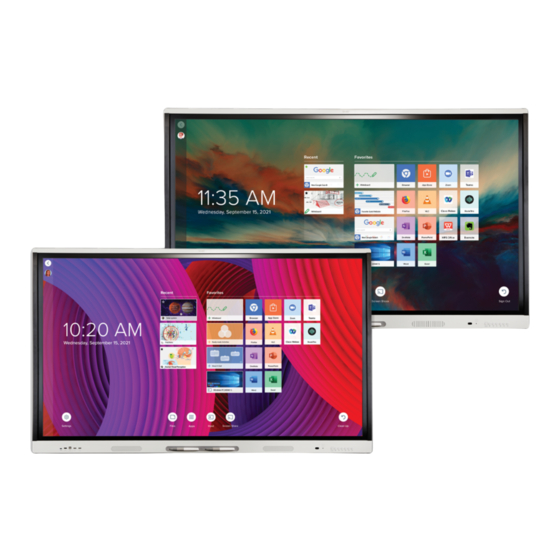
(see More information on page 17). About the display ® The SMART Board MX or MX Pro series interactive display with iQ is the hub of your classroom. The display includes an extensive set of features and components: Touch You can do everything on the display that you can do at your computer—open and close applications,... -
Page 12: Iq Experience
The 4K ultra-high-definition LCD display provides optimal image clarity and wide viewing angles. The size of the display varies by model: Models Size (diagonal) SBID-MX255-V4 / SBID-MX255-V4-PW / SBID-MX255-V3 / SBID-MX255-V3-PW 55" /P WSBID-MX255-V3N / SBID-MX255-V2-C / SBID-MX255-V2-CPW / SBID- MX255-V2 / SBID-MX255-V2-PW SBID-MX265-V4 / SBID-MX265-V4-PW / SBID-MX265-V3 / SBID-MX265-V3-PW 65"... -
Page 13: Room Computers And Guest Laptops
Chapter 1 Welcome You can connect to a network using Wi-Fi or the RJ45 LAN jack on the display: Wi-Fi supports both 2.4 and 5 GHz bands. The two RJ45 jacks allow you to connect the display and an external device, such as a computer, to a Ethernet network. -
Page 14: Front Control Panel
Chapter 1 Welcome Caution The SMART Board MX, MX (V2), MX (V2-C), and MX (V3) series accessory slot’s maximum available power is 60 W. The slot is not a limited power source. To reduce the risk of fire, make sure that accessories connecting to the slot satisfy the fire enclosure requirements of IEC 62368-1. -
Page 15: Identifying Your Specific Model
For more information about the remote control, see the SMART Board MX and MX Pro series interactive displays user guide (smarttech.com/kb/171554). Identifying your specific model There are several series of SMART Board MX and MX Pro series interactive displays: SMART Board MX SMART Board MX SMART Board MX SMART Board MX SMART ... -
Page 16: Accessories
Chapter 1 Welcome For help identifying your SMART Board MX (V2, V2-C, V3, or V4) series model, see the label on the left side of the display. Accessories Accessories for the display include: SMART OPS PC module Stands USB extenders Note For more information about these and other accessories, see smarttech.com/accessories. -
Page 17: More Information
Chapter 1 Welcome Stands If you want to move the display from place to place, you can install it on a SMART mobile stand. If you are installing the display on a wall that cannot support the display’s full weight, you can install the display on a SMART floor stand. -
Page 18: Chapter 2 Installing The Display
Chapter 2 Installing the display Moving the display to the installation site Using transportation aides Accommodating doorways, hallways, and elevators Dealing with cracked, chipped, or shattered glass Saving the original packaging Installing the display on a wall Choosing a location Choosing a height Assessing the wall Selecting mounting hardware... -
Page 19: Using Transportation Aides
Chapter 2 Installing the display Important Move the display at your own risk. SMART cannot accept liability for damages or injury that occur during the display’s transportation. When moving the display: Follow local safety regulations and standards. Pack the display in its original packaging, including the pallet. Move the display so that its top frame faces up. -
Page 20: Installing The Display On A Wall
Chapter 2 Installing the display Dealing with cracked, chipped, or shattered glass The display contains safety-tempered glass. Although this glass is heat-strengthened to help withstand impacts, the glass can crack, chip or shatter if struck with enough force. (Safety glass is designed to break into small pieces rather than sharp shards if it is broken.) Temperature changes can cause a minor crack or chip to become worse, possibly causing the glass to shatter. -
Page 21: Choosing A Location
Chapter 2 Installing the display Choosing a location A display is typically installed at the room’s focal point, such as at the front of a classroom or meeting space. Selecting an appropriate location for the display is crucial for ensuring the best possible experience with the product. - Page 22 Chapter 2 Installing the display Factor Considerations Visibility The display’s screen is clearly visible to all users in the room. SMART recommends users sit within a 178° viewing area: Note The viewing area depends on the display’s resolution and a variety of other factors.
-
Page 23: Choosing A Height
Chapter 2 Installing the display Factor Considerations Environment and The location meets the environmental requirements in the display’s specifications (see More information on page 17). ventilation The display isn’t subjected to strong vibrations or dust. Ventilation systems don’t blow air directly on the display. There is adequate ventilation or air conditioning around the display so that heat can flow away from it and the mounting equipment. -
Page 24: Selecting Mounting Hardware
SBID-MX255-V2, SBID-MX265-V2, MX275-V2 and MX286-V2 installation instructions (smarttech.com/kb/171547) SBID-MX255-V3, SBID-MX265-V3, MX275-V3 and MX286-V3 installation instructions (smarttech.com/kb/171785). SBID-MX255-V4, SBID-MX265-V4, MX275-V4 and MX286-V4 installation instructions (smarttech.com/kb/171835). Contact your authorized SMART reseller (smarttech.com/where) for information on SMART’s mounting options. If you choose a third-party option rather than one of SMART’s mounting options, be sure the wall mount can accommodate the display’s dimensions and support the display’s weight as well as the weight of... - Page 25 Chapter 2 Installing the display There are a number of potential hazards of mounting a display in a non-standard orientation or angle: Mounting a display horizontally (like a table top) can cause the glass to sag, damaging the display or interfering with the display’s touch system. Non-standard orientation can affect ventilation, creating hotpots in equipment, premature failures and, in displays that use projectors, exploding projector bulbs.
-
Page 26: Installing The Display On A Stand
Chapter 2 Installing the display If you’re not using the included bolts to fasten the wall mount to the display, see the following table. Display Bolt type Minimum length Maximum length SMART Board MX (V2, V2-C, V3, and V4) series 55"... -
Page 27: Installing The Iq Appliance And Intel Compute Card
Installing the iQ appliance and Intel Compute Card For SMART Board MX series displays For more information about installing the iQ appliance in SMART Board MX series displays, see the SMART Board MX series interactive display installation instructions (smarttech.com/kb/171274). Caution Install the AM50 iQ appliance and Intel Compute Card before you turn on the display for the first time. -
Page 28: Am50 Iq Appliance
Chapter 2 Installing the display The display requires a network and internet connection for downloading software and firmware updates, and a number of the iQ apps require a network connection as well. You can connect to a network using Wi-Fi or one of the RJ45 jacks. SMART ... -
Page 29: Connecting Power And Turning On The Display For The First Time
Chapter 2 Installing the display Wi-Fi connect an Ethernet cable from a network outlet directly to the AM50 appliance’s RJ45 jack connect an Ethernet cable from a network outlet to the display’s RJ45 IN jack, and then connect another Ethernet cable from the display’s RJ45 OUT jack to the AM50 appliance’s RJ45 jack Connecting power and turning on the display for the first time The final step in installing and configuring the display is to connect power and turn it on. - Page 30 Chapter 2 Installing the display To connect the display to power Connect the supplied power cable from the AC power inlet on the back of the display to a power outlet. 55" and 65" models 75" models 86" models Note Refer to the display’s specifications for power requirements and power consumption information (see More information on page ...
- Page 31 Chapter 2 Installing the display 1. Flick the switch beside the AC power inlet to the ON (I) position. SMART Board MX (V2, V2-C, V3, V4) series 55" models 65" models 75" and 86" models SMART Board MX series 65" models 75"...
-
Page 32: About Energy Saving Modes
Chapter 2 Installing the display 11. Tap Finish. The Welcome screen appears. The display downloads and applies updates for the firmware and system software. About energy saving modes The display features a number of energy saving modes: Networked standby: a low power state in which the display quickly turns on when the Power button is pressed. -
Page 33: Chapter 3 Connecting Computers And Other Devices
Chapter 3 Connecting computers and other devices Installing SMART software Connecting room computers and guest laptops Viewing a connected computer’s input Setting a connected computer’s resolution and refresh rate Connecting USB drives, peripherals, and other devices Troubleshooting connected computers Connecting a SMART OPS PC module Connecting other devices Connecting USB drives, peripherals, and other devices Connecting an external display... -
Page 34: Installing Smart Software
SMART Notebook basic Free software designed for use with a See Find out more about the version SMART Board interactive display. The basic basic version of SMART version of SMART Notebook software comes Notebook. with many features that you can use to create, edit, and deliver engaging lessons for your students. -
Page 35: Connecting Room Computers And Guest Laptops
You can connect cables for room computers and guest laptops. By installing cables in advance, you make use of connectors that might not be accessible after the display is wall-mounted. You can then run the cables across floors or behind walls as needed. SMART Board MX SMART Board MX SMART Board MX... - Page 36 Chapter 3 Connecting computers and other devices SMART Board MX (V4) series Side and bottom connector panels Front connector panel smarttech.com/kb/171555...
- Page 37 Chapter 3 Connecting computers and other devices SMART Board MX (V3) series Side and bottom connector panels Front connector panel SMART Board MX (V2-C) series Side and bottom connector panels Front connector panel smarttech.com/kb/171555...
- Page 38 Chapter 3 Connecting computers and other devices SMART Board MX (V2) series Side and bottom connector panels Front connector panel HDMI 3 smarttech.com/kb/171555...
- Page 39 Chapter 3 Connecting computers and other devices SMART Board MX series Side and bottom connector panels Front connector panel HDMI 1 HDMI 3 HDMI 2 Notes Install SMART software on any computers you connect to the display (see Installing SMART software on page ...
-
Page 40: Viewing A Connected Computer's Input
You can charge devices connected to the USB Type-C receptacle on the side connector panel of SMART Board MX (V3 and V4) series interactive displays up to 65 W (if a module is not installed in the accessory slot) or up to 30 W (if a module is installed in the accessory slot). -
Page 41: Setting A Connected Computer's Resolution And Refresh Rate
Chapter 3 Connecting computers and other devices To view the input of a computer connected to a SMART Board MX series display 1. Connect the computer to the display. 2. Press the Input on the front control panel. The Input selection menu appears. Note Inputs with devices connected are blue, and inputs without a connection are black. -
Page 42: Connecting A Smart Ops Pc Module
Chapter 3 Connecting computers and other devices The following table presents the recommend resolutions and refresh rates for the display’s VGA input source: Resolution Input source Mode Refresh rate aspect ratio 1920 × 1080 16:9 [N/A] 60.000 Hz 1600 × 1200 [N/A] 60.000 Hz 1360 ×... -
Page 43: Connecting Other Devices
(such as keyboards), and other devices to these connectors and use the devices with the iQ experience, connected computers, and devices installed in the accessory slot (such as the SMART OPS PC module). SMART Board MX (V4) series SMART Board MX (V3) series... - Page 44 (Hi-Speed) Located on the side connector panels of SMART Board MX (V2, V2-C, V3, and V4) series displays Located on the front connector panels of all displays and on the side connector panel of SMART Board MX series displays smarttech.com/kb/171555...
-
Page 45: Connecting An External Display
Located on the side connector panels of SMART Board MX (V2, V2-C, V3, and V4) series displays Located on the front connector panels of all displays and on the side connector panel of SMART Board MX series displays smarttech.com/kb/171555... -
Page 46: Connecting Room Control Systems
Chapter 3 Connecting computers and other devices SMART Board MX (V3) series SMART Board MX (V2 and V2- SMART Board MX series C) series In addition to the stereo 3.5 mm out connector, the display provides a Sony/Philips Digital Interface (S/PDIF) out connector (pictured). - Page 47 Chapter 3 Connecting computers and other devices You can use the display’s RS-232 connector to connect a third-party external control system to the display (see default.htm). Note Displays are not compatible with centralized remote control systems, such as a universal remote control.
-
Page 48: Connector Diagrams
Chapter 3 Connecting computers and other devices Connector diagrams SMART Board MX (V4) series Connector panel The following diagram and table present the connectors on the display’s connector panel: Side Bottom Connector Connects to Notes See page 35 and USB cables and USB Type-C USB Type-C 2 input connectors. -
Page 49: Front Connector Panel
Chapter 3 Connecting computers and other devices Connector Connects to Notes S/PDIF out Digital audio output See page 45 and Digital audio cables and connectors. RJ45 (×2) Network See page 27 and Ethernet (network) cables and connectors. Stereo 3.5 mm out External audio system See page ... - Page 50 Chapter 3 Connecting computers and other devices Side Bottom smarttech.com/kb/171555...
- Page 51 Chapter 3 Connecting computers and other devices Connector Connects to Notes See page 35 and USB cables and USB Type-C USB Type-C 2 input connectors. USB 3.0 Type-A [N/A] This connector is a service port. USB 3.0 Type-A Supported USB drives, See page ...
-
Page 52: Front Connector Panel
Chapter 3 Connecting computers and other devices Front connector panel The following diagram and table present the connectors on the display’s front connector panel: Connector Connects to Notes USB Type-C USB Type-C 1 input See page 35 and USB cables and connectors. - Page 53 Chapter 3 Connecting computers and other devices Side Bottom smarttech.com/kb/171555...
-
Page 54: Front Connector Panel
Chapter 3 Connecting computers and other devices Connector Connects to Notes See Connecting an external display on HDMI 2.0 out External display page 45 and HDMI cables and connectors. USB 2.0 Type-A [N/A] This connector is a service port. USB 3.0 Type-A Supported USB drives, See page ... - Page 55 Chapter 3 Connecting computers and other devices SMART Board MX (V2) series SMART Board MX (V2-C) series smarttech.com/kb/171555...
-
Page 56: Smart Board Mx Series
Chapter 3 Connecting computers and other devices Connector Connects to Notes USB 2.0 Type-A Supported USB drives, See page 43 and USB cables and peripherals, and other connectors. devices USB 2.0 Type-A Supported USB drives Connect a USB drive to update the connector display’s firmware. - Page 57 Chapter 3 Connecting computers and other devices Connector Connects to Notes HDMI 1.4 out (HDCP- External monitor This connector is HDCP-encrypted compliant) HDMI. Note HDMI out is an optional feature. Contact your authorized SMART reseller (smarttech.com/where) for further ordering instructions. USB 2.0 Type-A Supported USB drives, Connect a USB ...
-
Page 58: Front Connector Panel
Chapter 3 Connecting computers and other devices Front connector panel The following diagram and table present the connectors on the display’s front connector panel: Connector Connects to Notes USB 2.0 Type-A Supported USB drives, See page 43 and USB cables and peripherals, and other connectors. - Page 59 FCC warning: Any Changes or modifications not expressly approved by the party responsible for compliance could void the user's authority to operate the equipment. Note: This equipment has been tested and found to comply with the limits for a Class B digital device, pursuant to part 15 of the FCC Rules.
- Page 60 SMART Technologies smarttech.com/support smarttech.com/contactsupport smarttech.com/kb/171555...
Need help?
Do you have a question about the SBID-MX255-V4 and is the answer not in the manual?
Questions and answers