Table of Contents
Advertisement
Quick Links
Nippy 4
User's
,
Breas Nippy 4
User Manual
ENGLISH (GB)
006553
M-6 en-GB
USER MANUAL
Breas Medical AB, Företagsvägen 1, SE-435 33 Mölnlycke, Sweden
Phone +46 31 86 88 00 Order +46 31 86 88 20 Technical Support +46 31 86
88 60
7 321820 065530
Fax +46 31 86 88 10 www.breas.com, Date: 2022-11-22 | 20244
Advertisement
Table of Contents

Related Manuals for Breas Nippy 4


Summary of Contents for Breas Nippy 4
- Page 1 Breas Medical AB, Företagsvägen 1, SE-435 33 Mölnlycke, Sweden Phone +46 31 86 88 00 Order +46 31 86 88 20 Technical Support +46 31 86 88 60 7 321820 065530 Fax +46 31 86 88 10 www.breas.com, Date: 2022-11-22 | 20244...
-
Page 3: Table Of Contents
Checking the Nippy 4 before First Use........ - Page 4 5.1.1 Switch On and Enter Operating Mode ........42 5.1.2 Start the Pressure Ramp .
- Page 5 Using the Nippy 4 with the Trolley........
- Page 6 Cleaning the Nippy 4 ........
- Page 7 Nippy 4 Essential Performance ........
-
Page 9: Introduction
Every other use may lead to risk of personal injury! CAUTION! Read this manual thoroughly so that you completely understand how the Nippy 4 is operated and maintained before taking it into use, to ensure correct usage, maximum per- formance and serviceability. Non-professional caregivers (e.g. family members) should consult the medical equipment provider’s respiratory therapist if they have any questions... - Page 10 Compatible Patient Circuits The Nippy 4 should be used with a leakage circuit and a suitable patient interface or an MPV circuit. See 9 Accessories and Parts, page 130 for detailed information about approved patient circuits. The patient circuit shall comply to ISO 17510. The leakage should be at least 12 l/min at 4 O, to prevent rebreathing of exhaled air.
-
Page 11: Intended Use
Nippy 4 is intended for spontaneously breathing patients. Contraindications The Nippy 4 is not a life-support ventilator and is contraindicated in patients who are unable to tolerate more than brief interruptions in ventilation. If a patient has any of the following conditions, therapy with positive airway pressure may... -
Page 12: Intended Users
The User Manual contains the information intended for patients and lay operators. Training The lay operator shall be trained to basic knowledge of the Nippy 4 and in the specific operations they are assigned to perform. The training shall be based on the user manual and the responsible clinical personnel shall assess the level of training required for each lay operator. -
Page 13: About This Manual
Training and Certification Service personnel shall be trained on the Nippy 4 and certified by Breas for being allowed to perform any service, repairs or other operations on the Nippy 4. The training consists of reading the services manual in full. -
Page 14: Manufacturer Information
Information that may be valuable but is not of critical importance, tips. Reference Reference to other manuals with additional information on a specific topic. Manufacturer Information Legal Manufacturer Postal Address Breas Medical AB Företagsvägen 1 SE-435 33 Mölnlycke Sweden Web Address www.breas.com Email address breas@breas.com... - Page 15 UK Sales and Support Information UK Responsible Person: Breas Medical Ltd Phone UK Head Office +44 (0)1789293460 Fax UK Head Office +44 (0)1789262470 General Enquiries and Ordering orders@nippyventilator.com Tech Support techsupport@nippyventilator.com Introduction User Manual Doc. 006553 M-6...
-
Page 16: Safety Information
Every other use may lead to risk of personal injury! Risk of Insufficient Ventilation Usage outside the specified operating conditions may cause reduced performance. The Nippy 4 must only be used in accordance with the operating conditions specified in this manual. Risk of Reduced Safety and Performance Accessories that have not been tested with the Nippy 4 might affect safety features and performance negatively. - Page 17 The responsible organization should periodically reassess the settings of the therapy for effectiveness. Before starting treatment, always perform the procedure 4.5 Inspecting the Nippy 4 before Use , page 39. The ventilator is not suitable for a ventilator dependent patient.
-
Page 18: Electrical Safety
If you suspect that the device has been mistreated, perform a functional check before taking it to use. A basic functional check can be performed as described in 4.5 Inspecting the Nippy 4 before Use , page 39. A complete functional check can be performed by an authorized service technician. -
Page 19: Environmental Conditions
The delivered patient air can be as much as 4°C (7°F) higher than ambient temperature. Caution should be exercised if the room temperature is greater that 36°C (97°F). Risk of Faulty Treatment If a room humidifier is used, place it at least 2 meters away from the Nippy 4. Safety Information User Manual... -
Page 20: Usage Of Patient Circuit
Do not use or store the Nippy 4 in a magnetic resonance (MR) environment. Use of the Nippy 4 in an MR environment may result in malfunction of the Nippy 4 and pose unacceptable risk to the patient, medical staff or other persons. - Page 21 This port prevents rebreathing by flushing the exhaled air. • The Nippy 4 should be turned on and the function of the leakage port should be checked before use: The pressurized air from the Nippy 4 causes a continuous flow of air through the leakage port, enabling flushing of exhaled air.
-
Page 22: Usage Of Filters
WARNING! Risk of Cross-Contamination Patient circuits might get contaminated by exhaled gases. To avoid cross-contamination, always use a properly cleaned or a new patient circuit when the Nippy 4 is to be used by a new patient. NOTE For masks and accessories, always follow the manufacturer’s instructions. -
Page 23: Humidification
Risk of Insufficient Ventilation Insufficient ventilation may cause transient hypoxia. Do not use high resistance bacteria filter at the air outlet of the Nippy 4. High resistance bacteria filters placed between the air outlet and the patient interface may interfere with the operation of the patient disconnect function. -
Page 24: Cleaning And Maintenance
The Nippy 4 should be regularly cleaned and maintained in accordance with this operat- ing manual. WARNING! Risk of Faulty Treatment Service and Maintenance of the Nippy 4 shall not be performed when the Nippy 4 is in use. WARNING! Risk of Electric Shock High voltage contact may cause cardiac arrhythmia. -
Page 25: Usage Of Oxygen
The presence of oxygen can speed up combustion of inflammable materials. Risk of Fire When oxygen is used with the Nippy 4, the oxygen flow must be turned off when the Nippy 4 is not operating. Oxygen delivered into the patient tubing may accumulate within the machine enclosure. - Page 26 Supplemental oxygen flow and pressure must not exceed 30 l/min and 100 kPa. CAUTION! Supplemental oxygen is added before the volume measurement sensor and thereby included in the measurements. However, the oxygen concentration still has influence on the volume measurement of the delivered air. This measurement is based on a normal oxygen concentration of 21%.
-
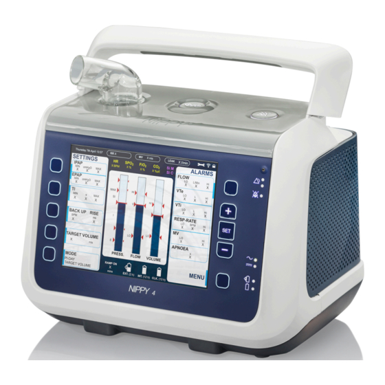
Page 27: Product Description
This section describes the components of the Nippy 4 medical electric equipment. NOTE • There might be local variations of the main components configuration. • The standard Nippy 4 and its packaging do not contain any natural rubber latex. Carry bag Function: Storage for transportation Part No: 006469 Manual... - Page 28 Function: Deliver power to the ventilator Part No: 006396 Power cord Function: Deliver power to the AC power supply Part No: GB: 003521 CN: 005304 EU: 003520 JP: 004834 US: 009024 Nippy 4 Main Unit Main Unit Product Description User Manual Doc. 006553 M-6...
-
Page 29: Front View
Front View 6, 7, 8 Item Function Alarms button Access to alarm settings Sensor Ambient light sensor 3–4 Alarm (red & yellow) LED Alarm indication: Red = High priority Yellow = Medium priority Audio pause LED Paused alarm sound indication Plus, Set, Minus buttons Function according to display Plus = Increase, go up... -
Page 30: Side Views
Side Views Click-in compartment side Item Function Audio pause Pause the alarm sound Start/Stop Start/Stop ventilation treatment Patient air outlet Connection for patient circuit Air bypass unit Click-in airway/silencer for use without the click-in humidifier. (If the click-in humidifier is used, it replaces the air bypass unit) Click-in compartment Compartment for either of... - Page 31 Filter Side Item Function Side panel Cover Memory card slot (SD card) Memory download Alarm beeper Alarm Sounds Output Patient air inlet Air bypass unit in, replaceable filters Internal battery Compartment for the internal battery sensor hatch Compartment for the optional sensor Product Description User Manual...
-
Page 32: Detaching And Reattaching The Side Panels
3.3.1 Detaching and Reattaching the Side Panels Detaching the Filter Side Panel 1 Lift the handle to access the release button (A). 2 Looking from behind, to dismount the filter side panel press the button above the panel (B). The panel is released. 3 Remove the panel. - Page 33 Reattaching the Click-in Compartment Side Panel 1 Lift the handle to access the release button (A). 2 To mount the click-in compartment side panel, insert the tabs (B) on the lower side of the panel into the holes (C). 3 Press the side panel into the casing until it clicks in place at the button (D).
-
Page 34: Equipment Designation
Equipment Designation Description Colour Item/Symbol Electrical connector, for power to the heated patient circuit. Connection for low pressure/bleed-in oxygen source interface port Remote start/stop, Audio pause, inter- face port Remote alarm and Nurse call interface port Network connection port Product Description User Manual Doc. -
Page 35: Additional Symbols
Mains/External DC 12-24V inlet 3.4.1 Additional Symbols This section describes symbols and markings that might appear on the parts or packaging of the Nippy 4. Symbol Description Internal battery Product number Read user instructions. Attention: Read the intended use in the manual. Read the Safety chapter in the manual. - Page 36 Symbol Description Date of Manufacture IEC protection Class II: Double insulated equipment. Indication of applied parts (IEC 60601-1 Type BF, Isolated Applied Part) (Symbol only applicable in U.S.) Caution: U.S. Federal law restricts this device to sale by or on the order of a licensed healthcare practitioner.
-
Page 37: Preparing The Nippy 4 For Use
(refer to the packing note or the invoice, if available). 2 Ensure that the equipment is in good condition. 3 If stored more than 1 month, connect the Nippy 4 to the power supply to recharge the internal battery. 4 Check that the grey and white air filters are installed. - Page 38 2 Make sure that nothing can block the patient air inlet. 3 Make sure that nothing can block the cooling air inlet or outlet. 4 Make sure that the controls are accessible for the operator. Preparing the Nippy 4 for Use User Manual Doc. 006553 M-6...
-
Page 39: Connecting The Nippy 4 To Mains
CAUTION! • Do not place the Nippy 4 on a soft surface that will prevent the air flow under- neath the device. Never cover the device. • Always position the Nippy 4 so the power supply lays on a surface without strain to the power cord. -
Page 40: Connecting The Patient Circuit
3 Connect the power supply’s power cord to the mains supply. To isolate the Nippy 4 from the mains supply, disconnect the power supply. Connecting the Patient Circuit WARNING! Read 2.4 Usage of Patient Circuit, page 18 carefully to make sure all conditions are consid- ered and met. -
Page 41: Inspecting The Nippy 4 Before Use
Check that the cables are properly connected. Inspection of Placement • The Nippy 4 shall be placed on solid flat surface below the patient level (see 4.2 Placing the Nippy 4, page 35). • Make sure that nothing can block the air inlet at the side. -
Page 42: Adjusting The Nippy 4 Patient Settings
CAUTION! A pre-user test is recommended if the patient circuit configuration has been changed. NOTE If the pre-use test has not been performed, the Nippy 4 will operate with default patient circuit compensation. Starting the Pre-use Test Manually 1 On the Menu, select Pre-use Test and then START PRE-USE TEST. -
Page 43: Actions At Pre-Use Test Failure
The result will be displayed for review. Block the end of the patient circuit with an air tight object. Wait while the Nippy 4 is checking the patient circuit compliance and leakage. Test finished. Review the test result. -
Page 44: How To Use The Nippy 4
⇒The Nippy 4 needs about 15 seconds to power up and enter standby mode. 2 If running the Nippy 4 on the internal battery or the click-in battery, press the Start/Stop button. ⇒The Nippy 4 needs about 15 seconds to power up and enter standby mode. -
Page 45: Start The Pressure Ramp
The ramp buttons are only available after the treatment has started. 1 Press the Start Ramp button. 2 Confirm to start the ramp. 3 Read and acknowledge the information message regarding reduced alarm functionality during the ramp period. How to Use the Nippy 4 User Manual Doc. 006553 M-6... -
Page 46: Stop The Pressure Ramp
1 To stop treatment and enter standby mode, first press and hold the Start/Stop button on the front panel. 2 Release the Start/Stop button when the progress bar is filled. How to Use the Nippy 4 User Manual Doc. 006553 M-6... -
Page 47: Turn Off / Enter Sleep Mode
Turn off / Enter Sleep Mode If the Nippy 4. is running on batteries, this procedure turns it off. If the Nippy 4. is connected to mains, this procedure puts it in sleep mode (all functions are off, except battery charging) -
Page 48: Navigating The Display
Menu/More button Use this button to open the menu for accessing information and settings for the device and for comfort functions. How to Use the Nippy 4 User Manual Doc. 006553 M-6... -
Page 49: Symbols Used On The Display
Internal battery For battery level information, see 5.11 Using Batteries, page 61. Click-in battery (accessory)For battery level information, see 5.11 Using Batteries, page 61. Keypad lock activated Keypad lock deactivated How to Use the Nippy 4 User Manual Doc. 006553 M-6... -
Page 50: Display Overview
Multiple pages Press the MORE button to display the next page. Display Overview 5.4.1 Home Mode In Home Mode, the Nippy 4 start screen has the following layout: Alarms IPAP, EPAP TI, Backup Insp. Time Navigation buttons Backup, Rise... -
Page 51: Profiles
Minimum/maximum working IPAP is limited/achieved by a software control of blower speed vs. measured pressure. Unit Default 5.6.2.2 EPAP The EPAP setting is used to define the airway pressure at the end of the expiratory phase. How to Use the Nippy 4 User Manual Doc. 006553 M-6... - Page 52 Backup Rate. The combination of the Backup Inspiratory Time and Backup Rate setting is limited by the I:E ratio 2:1. Unit Default How to Use the Nippy 4 User Manual Doc. 006553 M-6...
- Page 53 When the patient starts a breath, an increasing flow is created in the patient circuit. If the patient’s effort reaches the set inspiratory trigger level an inspiration is initiated. How to Use the Nippy 4 User Manual Doc. 006553 M-6...
- Page 54 Inspiratory Pressure between two adjustable pressure limits: Min Pressure and Max Pressure. When Target Volume is active, the mode field on the ventilator display will indicate "(TgV)". Unit Default 2000 How to Use the Nippy 4 User Manual Doc. 006553 M-6...
- Page 55 Ramp Time. Unit Default Current IPAP–2 5.6.2.17 Always Start Ramp The Always Start Ramp determines whether the ramp is started automatically at the begin- ning of the treatment. How to Use the Nippy 4 User Manual Doc. 006553 M-6...
-
Page 56: The Alarms List
The Alarms list displays the alarm settings. Which alarms that are available depends on the current treatment mode and settings. The Monitored Values Pane This section describes the monitored treatment values that are displayed on the start screen How to Use the Nippy 4 User Manual Doc. 006553 M-6... - Page 57 To the left of the bar a mark discloses the highest pressure during last breath. • To the right of the bar marks discloses the set values for IPAP and EPAP. • Red lines in the bar indicates alarm levels. How to Use the Nippy 4 User Manual Doc. 006553 M-6...
-
Page 58: The Menu
Note that only menu items applicable for the current mode are available. 5.9.1 Humidification Settings This menu item lets you make changes to the humidifier and the heated circuit settings. How to Use the Nippy 4 User Manual Doc. 006553 M-6... -
Page 59: Sigh Settings
5.9.3 Pre-Use Test This menu item is only available in clinical mode and when the Nippy 4 is in standby mode. This menu item contains: • Start Pre-use Test On/Off (Selects whether a pre-use test shall be prompted every time the Nippy 4 is powered on). -
Page 60: Compliance Data (Optional)
5.9.5 Compliance Data (Optional) Compliance data is statistics of usage, such as usage hours and days used. From this menu item you view the compliance data, if the Nippy 4 has been configured to show it. 5.9.6 Alarm/Event Logs This menu item displays the alarm and event logs. -
Page 61: Transferring Data Between The Ventilator And A Pc
Read the chapter 2.2 Electrical Safety, page 16 carefully to make sure all conditions are con- sidered and met. CAUTION! Do not eject the memory card or disconnect the USB cable while the Nippy 4 is transfer- ring data. Doing so may result in loss of data and/or damaged equipment. NOTE In order to view and present patient data, Breas software must be used. -
Page 62: Transferring Data With A Memory Card
With a USB cable, real-time data can also be received and sent between the ventilator and a 1 Connect the USB cable to the ventilator. Make sure it is fitted correctly. 2 Connect the other end of the cable to a PC running Breas PC software. How to Use the Nippy 4 User Manual... -
Page 63: Using Batteries
The internal and click-in batteries in the ventilator are of the Lithium-ion type, which is a high performance battery. It has a long expected lifetime, low weight in relation to its capacity and low self discharge. See the Nippy 4 Service Manual on how to perform service on the batteries. 5.11.1 Power Source Priority 1. -
Page 64: Charging The Batteries
To ensure that the batteries are fully charged, a maintaining charging cycle will be performed. The batteries are not charged when connecting the Nippy 4 to an external DC supply. While charging, the battery level will be animated. The batteries are only charged if the internal temperatures are between 0 to 45°C (32 to 113°F). -
Page 65: Internal Battery
The click-in battery can be replaced during treatment, provided that the internal battery is charged. Connect the Click-in Battery 1 Release the side cover by pressing the button under the handle. How to Use the Nippy 4 User Manual Doc. 006553 M-6... -
Page 66: Battery Operating Time (Internal And Click-In)
5.11.6 Battery Operating Time (Internal and Click-in) The operation time is dependent on the battery condition, its capacity, the ambient air tem- perature and the Nippy 4 pressure setting. These data are based on new and fully charged batteries. Parameter... -
Page 67: Storing The Internal Battery And The Click-In Battery
Do not connect the ventilator to a wheelchair unless the operating manual for the wheel- chair permits this as this can affect the ventilator performance and consequently result in patient death. How to Use the Nippy 4 User Manual Doc. 006553 M-6... -
Page 68: Using Accessories
Both AC power supply and external DC using the Y-cable. With an external DC source connected, the Nippy 4 will automatically switch over to the external DC source if the mains power cord is removed or if the mains power supply fails. -
Page 69: Using The Ventilator With A Nurse Call System
The FiO meas- urements will be stored in the data memory which can be downloaded to a PC and viewed in Breas software. How to Use the Nippy 4 User Manual Doc. 006553 M-6... - Page 70 1 Place the ventilator so the bottom is accessible. 2 Remove the hatch for FiO sensor. Use a torx TX10 screwdriver. 3 Insert the FiO sensor with the electrical contact side in. How to Use the Nippy 4 User Manual Doc. 006553 M-6...
-
Page 71: Using The Ventilator With The Remote Alarm
PC and viewed in the Breas PC software. When installed, the Nippy 4 automatically detects the sensor, also after powering off/on and after power failure. How to Use the Nippy 4 User Manual Doc. -
Page 72: Using The Ventilator With The Remote Start/Stop
2. Port for patient circuit 3. Cooling air inlet 4. Port for cables and O inlet 5. Mounting straps 6. Patient air inlet CAUTION! Do not cover the air inlets or outlets. How to Use the Nippy 4 User Manual Doc. 006553 M-6... -
Page 73: Using The Nippy 4 With The Trolley
The trolley shall only be used in indoor, hospital environment. The trolley system consists of a trolley base and a mounting bracket. This section describes how to use the Nippy 4 and a trolley with mounting bracket. Mount and dismount the Nippy 4 as shown in the picture: The bottom plate is mounted to the trolley using two screws. -
Page 74: Using The Click-In Humidifier
The click-in humidifier is intended to humidify the patient air. It is intended for non-invasive use only. The click-in water chamber is for single patient use only. Reusing a water chamber for a new patient might cause a risk of cross-contamination. The Nippy 4 shall not be moved with a filled water chamber installed. - Page 75 If the ventilator is equipped with click-in battery, remove it before installing the water chamber. Follow the instructions in the illustration below to install the water chamber to the ventilator How to Use the Nippy 4 User Manual Doc. 006553 M-6...
- Page 76 The click-in humidifier only operates during treatment. When the ventilator is in standby mode, the humidification is paused. Prerequisites • The water chamber shall be filled with water and attached. • The ventilator shall be connected to the mains power supply How to Use the Nippy 4 User Manual Doc. 006553 M-6...
- Page 77 Always stop treatment before detaching or attaching the water chamber. Make sure the Nippy 4 with the attached water chamber is placed lower than the patient and on a flat surface. This is to prevent personal injury from accidental spillage or from excess water or condensation flowing down the patient tube and into the patient’s...
- Page 78 For disinfecting the water chamber, use any of the agents listed below. Follow the provider’s instructions. The water chamber will withstand at least 20 disinfections without degradation. Disinfection Agent Duration 15 minutes Gigasept® FF 5% solution Steranios 2% solution 10 minutes How to Use the Nippy 4 User Manual Doc. 006553 M-6...
-
Page 79: 5.12.10 Using The Patient Circuit With Heated Wire
2 Select Heated Circuit Temp and set the temperature according to the respiratory therapist’s prescription. 3 Select Circuit Heating and set it to On. The circuit heating is now activated and will start to operate when the treatment starts. How to Use the Nippy 4 User Manual Doc. 006553 M-6... -
Page 80: Alarms
Never leave a patient unattended during an alarm condition. Setting alarm limits to extreme values could put the patient at risk. Permitted distributed alarm systems are Nippy 4 remote alarm with cable and Nippy 4 nurse call cables provided by Breas Medical only. -
Page 81: Audible Signal Pause
Alarm text in display Displays the name of the active alarm con- dition and a guiding text. The priority of the alarm is indicated by the background colour • Red = High priority • Yellow = Medium priority Audible signals •... -
Page 82: Audible Signal Presilence
6.1.3 Audible Signal Presilence The audible signal can be turned off for the coming 2 minutes. CAUTION! During the presilence period, any new alarms will only be indicated by the visual signals, the audible signal will not be activated. NOTE Power Failure and Function Failure alarms are not affected by presilence and, if triggered, will sound during the presilence period. -
Page 83: High Flow Alarm
Setting display The alarm setting is also displayed by a red line in the Flow bar graph. Ventilator action The Nippy 4 will continue treatment with the current settings, and try to compensate for unintentional leakages. Alarms User Manual Doc. 006553 M-6... -
Page 84: Low Flow Alarm
Below 40 l/min: 1 l/min Above 40 l/min: 5 l/min Setting display The alarm setting is displayed by a red line in the Flow bar graph. Ventilator action The Nippy 4 will continue treatment with the current settings. Alarms User Manual Doc. 006553 M-6... -
Page 85: High Pressure Alarm
A full breath is performed with maximum pressure below the alarm limit. Ventilator action The Nippy 4 will continue treatment according to the current settings. The actual breath is however terminated if the High Pressure alarm limit is reached. Setting range •... -
Page 86: Low Pressure Alarm
Alarm text Priority High Alarm condition A Low Pressure alarm will be given when the Nippy 4 pressure fails to reach the low pressure alarm limit for 15 seconds. The low pressure alarm is disabled during ramp periods. Possible cause •... -
Page 87: High Epap Alarm
Changes in airway resistance and or compliance. Reset criteria EPAP has gone below the alarm limit (lower than 30% above the set value). Ventilator action The Nippy 4 will continue treatment according to the current settings. Setting range • •... -
Page 88: High Vt
6.3.7 High Vt Alarm (High Expired Tidal Volume) Property Description High Vte Alarm text Priority Medium Alarm condition A High Expired Tidal Volume alarm will be given when the monitored Expired Tidal Volume exceeds the alarm limit for 15 seconds. Possible cause •... -
Page 89: High Mv E (High Expired Minute Volume Alarm)
6.3.9 High MV (High Expired Minute Volume Alarm) Item Description High MVe Alarm text Priority Medium Alarm condition A High Expired Minute Volume alarm will be given when the monitored expired minute volume exceeds the alarm limit for 15 seconds. Possible cause •... -
Page 90: High Breath Rate Alarm
• Too sensitive setting of the inspiratory trigger setting. Reset criteria The breath rate goes below the alarm limit. Ventilator action The Nippy 4 will continue treatment according to the current settings. Setting range • 10 bpm to 70 bpm •... -
Page 91: Low Breath Rate Alarm
Decrease in the patient’s spontaneous breathing. • Circuit disconnection. Reset criteria The breath rate goes above the alarm limit. Ventilator action The Nippy 4 will continue treatment according to the current settings. Setting range • 4 bpm to 40 bpm •... -
Page 92: Apnoea Alarm
• Inspiratory Trigger is set too high. Reset criteria Inspiratory effort detected by the Nippy 4. Ventilator action The Nippy 4 will continue treatment according to the current settings. Setting range • 5 to 60 s. (Non MPV mode) •... -
Page 93: Rebreathing Alarm
Too high leakage in the patient circuit. • The patient has removed the mask. • Circuit disconnection. Reset criteria The leakage is back within limits. Ventilator action The Nippy 4 will continue treatment according to the current settings Setting range • • 6.3.15 Rebreathing Alarm Property... -
Page 94: Obstruction Alarm
6.3.16 Obstruction Alarm Property Description Obstruction Alarm text Priority High Alarm condition An Obstruction alarm will be given if the inspiratory breathing tube becomes blocked and remains blocked for 2 consecutive breaths. Ventilator action With each breath cycle, upon detection of an obstruction the ventilator will reduce the airway pressure to the set EPAP. -
Page 95: Low Fio
Possible cause Too high flow of bleed-in oxygen. Reset criteria The SpO value goes back below the alarm limit. Ventilator action The Nippy 4 will continue treatment according to the current settings. Setting range • 90 % to 100 % •... -
Page 96: Low Spo
Bad positioning of the finger probe. Reset criteria The pulse rate goes back below the alarm limit. Ventilator action The Nippy 4 will continue treatment according to the current settings. Setting range 30 to 230 bpm (beats per minute) Setting resolution... -
Page 97: 6.3.22 Low Pulse Rate Alarm
Reset criteria External power supply connected to ventilator. Ventilator action The Nippy 4 stops the treatment, and gives the Power Fail alarm for at least 2 minutes. If power is restored within the alarm time, the ventilator will automatically resume treatment with current settings. -
Page 98: High Patient Air Temp. (High Patient Air Temperature)
This alarm will be given when the last battery source (internal battery) has 15 minutes of operating time left with current settings. Ventilator action The Nippy 4 will continue treatment according to the current settings. Alarms User Manual Doc. 006553 M-6... -
Page 99: Crit. Low Last Power Source Alarm
6.4.5 Crit. Low Last Power Source Alarm Property Description Crit. Low Last Power Source Alarm text Alarm condition A Crit. Low Last Power Source alarm will be given when the last battery source (internal battery or click-in battery) has 5 minutes of operating time left with current settings. Priority High Ventilator action... -
Page 100: Poor Spo2 Signal
6.4.8 Signal Lost Alarm Property Description Alarm text SPO2 Signal Lost signal lost. Alarm condition Priority High Possible cause Signal lost reported by SpO electronics (due to patient remov- ing the probe from finger, or sensor detached from SpO electronics. Ventilator action The ventilator will continue treatment with the same settings. -
Page 101: Fio2 Disconnected
Ventilator action The Nippy 4 will continue treatment according to the current settings. Normal atmospheric pressure at sea level will be used as approximation for the temporary ambient pressure compensa- tion. -
Page 102: Temperature Comp. Lost
6.4.12 Temperature Comp. Lost (Ambient Temperature Compensation Lost Alarm) Property Description Alarm text Temperature Comp. Lost Alarm condition An Ambient Temperature Compensation Lost alarm will be given when the automatic ambient temperature compensation is out of order. There is no communication with the air temperature sensor or the value is out of range (less than -30°C (-22°F) or more than 70°C (158°F). -
Page 103: Led Failure Alarm
6.4.14 LED Failure Alarm Property Description LED Failure Alarm text Alarm condition A LED Failure alarm will be given when one or more LED indicators on the front panel are broken. Priority Medium Ventilator action The ventilator will continue treatment with the same settings. Reset Power-on reset of ventilator (or repair). -
Page 104: Internal/Click-In Battery Hot Alarm
6.4.17 Internal/Click-In Battery Hot Alarm Property Description Internal Battery — Internal Battery Hot Alarm text Click-In Battery — Click-In Battery Hot Alarm condition An alarm for Internal/Click-In Battery Overheat in Discharge will be given when the internal or click-in battery reaches 55°C (131°F). -
Page 105: High Humidifier Temp. Alarm
6.4.19 High Humidifier Temp. Alarm Property Description Alarm text High Humidifier Temp. Alarm condition A Humidifier High Temperature alarm will be given if the humidifier heater plate temperature exceeds 76°C (169°F) for more than 2 seconds. Priority Medium Ventilator action The ventilator will turn off the click-in humidifier and then con- tinue treatment with the same settings. -
Page 106: Heated Circuit Fault Alarm
The ventilator will stop the treatment and shut down. Action to take Restart the Nippy 4. If the alarm persists or reoccurs: Take a note of the error code and contact your supplier of the Nippy 4 . Alarms User Manual Doc. 006553 M-6... -
Page 107: 6.4.23 Air Temp. Sensor Fail Alarm
6.4.23 Air Temp. Sensor Fail Alarm Property Description Alarm text Air Temp Sensor Fail Alarm condition The alarm is given in case of swivel boot temperature sensor communication failure or sensor reporting temperatures out of range (below -30°C (-22°F) or above 60°C (140°F). Priority Medium Ventilator action... -
Page 108: 6.4.26 Cooling Fan Error Alarm
6.4.26 Cooling Fan Error Alarm Property Description Alarm text Cooling Fan Error Alarm Condition The Cooling Fan Error alarm shall be given when the cooling fan runs too slow. Priority High Ventilator action The ventilator will continue treatment with the same settings. Reset When cooling fan speed is above 275 rpm. -
Page 109: 6.4.29 Humidifier/Bypass Loose Alarm
The audio pause LED lights yellow. • In about a second, both LEDs are turned off. If the test fails, do not use the Nippy 4. Contact your supplier of the Nippy 4 for a technical check. 6.5.2 Mandatory Alarm Tests This alarm test should be performed when changing patient, if the ventilator’s function... - Page 110 EPAP 5 cmH Rise Time Insp. Trigger Exp. Trigger Min Insp. Time Max Insp. Time Backup Rate 12 bpm 2.0 s Backup Insp. Time Target Volume 5 All alarm settings shall be set to Off if possible. 6 Start the treatment. 6.5.2.1 High and Low Flow Alarm Tests 1 Set the high flow alarm to 20 l/min.
-
Page 111: Optional Alarm Tests
1 Connect SpO sensor to device and to your finger. 2 Set the low SpO alarm to 85%. 3 Set the high SpO alarm to be 90%. 4 Start treatment and wait 30 s. ⇒ High SpO alarm should be given. 5 Stop treatment. - Page 112 6.5.3.1 High EPAP Alarm 1 Connect the ventilator patient circuit to a test lung and a CPAP device. Set the CPAP device treatment pressure to 10 cmH 3 Adjust the ventilator settings as follows: Setting Value Ventilation Mode IPAP 15 cmH 5 cmH EPAP Breath Rate...
-
Page 113: Cleaning And Maintenance
2 Remove the patient circuit. 3 Disconnect all electric cables. 4 Clean the outside of the Nippy 4 using a lint-free cloth with a mild soap solution, and/ or ethanol 70% for surface disinfection. 5 If the click-in humidifier is used, clean it as described in 5.12.9.6 Cleaning the Water Chamber, page 76. -
Page 114: Air Pathway Disinfection
• Air inlet with filters In case of contamination, the internal air pathways of the Nippy 4 may be disinfected up to 5 times by a maximum 60 minute long validated ozone gas process. Low resistance bacteria filter, if used, should be replaced every 24 hours. -
Page 115: Washing A Coarse Filter
2 First Place the filters in the air inlet compartment, with the coarse filter outside the fine filter. 3 Close the side panel carefully for not displacing the filters while closing. For detailed information about closing the side panel, see 3.3.1 Detaching and Reattaching the Side Panels, page 30. -
Page 116: Change Of Patients
Service and Repair The service and repair of the ventilator must only be carried out by authorised service per- sonnel in accordance with Breas service instructions. Service inspections must always be car- ried out following any repairs to the device. - Page 117 NOTE Batteries used with the ventilator shall be recycled in accordance with the local environ- mental regulations. Cleaning and Maintenance User Manual Doc. 006553 M-6...
-
Page 118: Technical Specifications
Technical Specifications System Description Leakage Port Configuration This diagram provides an overview of the ventilator system when used with a leakage port patient circuit. 1. Nippy 4 2. Tube 3. Leakage port / Patient interface connection 4. Patient 8.1.1 Pneumatic Diagram for the ventilator... -
Page 119: Data
Data 8.2.1 Worst Case Accuracy Pressure Control Modes The worst case Nippy 4 configuration is the 15 mm patient circuit with HCH humidifier and bacterial filter. 8.2.2 Modes Specifications This section lists the settings that can be made for the ventilator’s modes. - Page 120 Technical Specifications User Manual Doc. 006553 M-6...
- Page 121 Technical Specifications User Manual Doc. 006553 M-6...
- Page 122 Technical Specifications User Manual Doc. 006553 M-6...
-
Page 123: Monitored Values Specifications
8.2.4 Monitored Values Specifications This section describes the ranges and tolerances for monitored values on the Nippy 4. All stated tolerances include measurement uncertainty. The accuracies have been tested with all allowed configurations. Stated tolerances only disclose the maximum tolerance. -
Page 124: Power Supply
Spont Rate Range/Performance: 0 to 99 bpm. Tolerance: ±1 bpm % Spont Range/Performance: 0 to 100%. Range/Performance: 70 to 100%. Tolerance: ±3 digits. No motion and flex sensor. Pulse Rate Range/Performance: 25 to 240 bpm. Tolerance: ±3 digits. No motion and flex sensor. Range/Performance: 1:10 to 10:1. -
Page 125: Other
Maximum limited pressure during single fault condition: 80 cmH2O (PCV, PSV) 30 cmH2O (CPAP) Breathing resistance under single-fault: <6 cmH2O at 30 l/min, <6 cmH2O at 60 l/ Nippy 4 Dimensions W × H × D: 216 × 159 × 152 mm Weight: 2.4 kg... -
Page 126: Emission And Immunity Declaration
The performance of all functions of the ventilator is considered as essential performance for the purpose of immunity testing. 8.3.1 Nippy 4 Essential Performance The ventilator will deliver ventilation at the patient-connection port within its published accuracy specifications and within the alarm limits set by the operator, or generate an alarm... - Page 127 IEC 61000-4-8 in a typical commercial, hospi- tal and residential environment. Voltage dips, short 0% U , 0.5 cycle (multiple Nippy 4 runs on internal bat- phase analysis); interruptions and tery during voltage dips, short voltage variations 0% U , 1 cycle;...
- Page 128 Immunity Test Compliance Level Electromagnetic Environ- ment - Guidance Conducted RF IEC (150 kHz to 80 MHz) d=0.35*√P m at 150 kHz to 61000-4-6 (inside ISM/ASR 80 MHz bands) Radiated RF IEC 10 V/m 80 MHz to 2.5 GHz d= 1.2*√P m at 80 MHz to 61000-4-3 800 MHz d= 2.3*√P m at 800 MHz to...
-
Page 129: Emission
8.3.3 Guidance and Manufacturer's Declaration – Electromagnetic Emission The ventilator is intended for use in the electromagnetic environment specified below. The customer or the user of the ventilator should assure that it is used in such an environment. Emissions test Compliance Level Electromagnetic Environ- ment - Guidance... -
Page 130: Recommended Separation Distances Between External Power
8.3.5 Recommended separation distances between external power conductors and the ventilator Rated maximum current in Separation distance (m) conductor (A) 50-60 Hz d= I/2πH= I/188 0.005 0.05 0.16 For conductors rated at a maximum current not listed above, the recommended separation distance d in metres (m) can be estimated using the equation d=I/2πH, where I is the maxi- mum current rating of the conductor in amperes (A) according to the transmitter manufac- turer;... - Page 131 Delivery Settings, Alarms High Pressure Alarm: 25 cmH Low Pressure Alarm: 10 cmH High EPAP Alarm: Off Low EPAP Alarm: Off High Flow Alarm: 100 l/min Low Flow Alarm: 20 l/min High Vt Alarm: 500 ml Low Vt Alarm: 300 ml High MV Alarm: Off Low MV...
-
Page 132: Accessories And Parts
Accessories and Parts WARNING! Only use accessories recommended by Breas Medical. Breas Medical cannot guarantee the performance and safety for the use of other accessories with the ventilator. NOTE Accessory equipment connected to the analogue and digital interfaces must be certified according to the respective IEC standards (e.g. - Page 133 Circuit: Single limb 22 mm, disposable Function: Delivers air to the patient, applied part Part No: 008426 (30-pack of 004465) Circuit: Single limb heated wire 15 mm, disposable Function: Deliver heated air to the patient, non-invasively Part No: 006193 Circuit: 1.8m x 15mm Smoothbore Disposable Function: Deliver air to the patient Part No: 009119 Circuit: Single limb 15 mm...
- Page 134 BFE (Bacterial Filtration Efficiency): 99.9999% • VFE (Viral Filtration Efficiency): 99.999 % Part No: 007963 Low pressure oxygen adapter Function: Oxygen tube adapter with con- nector for the Nippy 4. Part No: 005032 Accessories and Parts User Manual Doc. 006553 M-6...
-
Page 135: Power Accessories
Circuit: Single limb for Mouthpiece ventilation (MPV) Function: Deliver air to the patient Part No: 006093 Mouthpiece Function: Patient interface for Mouthpiece ventilation (MPV) Part No: 006094 MPV arm Function: Hold an MPV circuit so Mouth- piece can be mounted close to the patient Part No: 006095 Power Accessories Car Adapter Cable... - Page 136 EU: 003520 JP: 004834 US: 009024 XPAC - External battery with charger Function: Extends usage time of sup- ported Breas products. Part No Cable for connection to device: 007671 Part No Charger with cable: Single: Charger with one battery Dual: Charger with two batteries...
-
Page 137: Monitoring Accessories
Monitoring Accessories Breas PC software Function: Data monitoring software Part No: 006718 USB cable Function: Data cable: PC to Nippy 4 (USB to USB) Part No: 005757 Memory card Function: Storage and transfer of settings, patient data and usage data... - Page 138 Memory card reader/writer Function: Read/write memory card Part No: 002185 Remote alarm with cable Function: Monitor Nippy 4 alarms remotely Part No: 10 m: 006348, 25 m: 006349 Remote alarm cable Function: Part No: 10 m: 006359, 25 m: 006360, 50...
- Page 139 Remote start/stop Function: Start and stop the ventilator remotely. Also, pause audio remotely. Part No: 006649 sensor Function: Measure FiO to the patient. Part No: 006172 module Function: Connection interface Part No: 006369 sensor Function: Finger Clip SpO sensor Part No: Adult: 006589 Paediatric: 006590 Accessories and Parts...
-
Page 140: Ventilator Filters And Detachable Parts
sensor Function: Multisite SpO sensor Part No: 006591 Ventilator Filters and Detachable Parts Patient air inlet filter, fine, white, disposable Function: Fine inlet air filtration. Material: AS 100 NaCl Penetration: (0.65 μm NaCl @ 95 l/min) = <7.35% Part No: 007103 (5pcs) Patient air inlet filter, coarse, grey, washable Function: Coarse inlet air filtration Material: Bulpren S 28133... - Page 141 Air bypass unit Function: Direct the air flow within the ventilator Part No: 007064 Click-in water chamber Function: Humidify the patient air Part No: 006490 Side panels Function: Protect the internal ventilator components. Part No: Grey: 007065, Blue: 007066, Light blue: 007518 Accessories and Parts User Manual Doc.
-
Page 142: Other Accessories
Other Accessories Trolley Function: Mobile use, transportation Part No: 007384 Universal rail clamp Function: Attach a humidifier to a trolley. Part No: 007858 E-cylinder holder Function: Attach an E-cylinder to a trolley. Part No: 005128 Accessories and Parts User Manual Doc. - Page 143 IV-pole Function: Pole with hooks to hang IV fluid bags. Part No: 007859 Mounting bracket Function: Mount the ventilator to a stand / trolley / rail system. Part No: 006761 Protective cover Function: Shock protection Part No: 006067 Lightweight Mobility Bag Function: Mobile use Part No: 007555 Accessories and Parts...
- Page 144 Carry bag Function: Storage for transportation Part No: 006469 Accessories and Parts User Manual Doc. 006553 M-6...
-
Page 145: Patient Settings
Patient Settings This section can be copied and used for noting the patient’s settings. Patient Settings User Manual Doc. 006553 M-6... - Page 146 Patient Settings - Nippy 4 Patient ....................Date ....................Clinic ....................Set by ....................Ventilation mode:................Patient Circuit IPAP Inspiratory Trigger EPAP Expiratory Trigger Breath Rate Min Inspiratory Time Inspiratory Time Max Inspiratory Time Backup Rate Backup Inspiratory Time Target Volume...
-
Page 147: Faa Compliance
Electromagnetic Compatibility (EMC) in accordance with the current version of RTCA/DO-160, Section 21, Category M. Breas Medical has successfully completed testing for the ventilator System. The ventilator System complies with RTCA/DO-160, Section 21, Category M and can be considered FAA compliant. -
Page 149: Index
Index Internal Function Failure ..104 Internal temp high ....106 +/- buttons ......27 Internal/Click-In Battery Hot . - Page 150 inspect ......39 Caution Electrical safety Icon....... . . 11 user precautions.
- Page 151 High MVe alarm ..... . 87 Leakage circuit (single limb) High Patient Air Temperature pneumatic diagram....116 Alarm (High Patient Air Temp) alarm .
- Page 152 Operating conditions specifications ..... .117 Ramp time ......53 Operator’s position Rebreathing alarm .
- Page 153 Sensor Failure/Discon- nection Alarm (SpO Discon- nected) alarm ......97 Start pressure (ramp) ....53 Start-Stop using remote .
Need help?
Do you have a question about the Nippy 4 and is the answer not in the manual?
Questions and answers