
Subscribe to Our Youtube Channel
Related Manuals for Pfeiffer Vacuum HILOBE 14004


Summary of Contents for Pfeiffer Vacuum HILOBE 14004
- Page 1 OPERATING INSTRUCTIONS Translation of the Original HILOBE 14004 Roots pump without electronic drive unit...
- Page 2 Dear Customer, Thank you for choosing a Pfeiffer Vacuum product. Your new roots pump should support you in your individual application with full performance and without malfunctions. The name Pfeiffer Vacuum stands for high-quality vacuum technology, a comprehensive and complete range of top-quality products and first-class service.
-
Page 3: Table Of Contents
Table of contents Table of contents About this manual Validity 1.1.1 Applicable documents 1.1.2 Variants Target group Conventions 1.3.1 Instructions in the text 1.3.2 Pictographs 1.3.3 Labels on product 1.3.4 Abbreviations Safety General safety information Safety instructions Safety precautions Limits of use Proper use Foreseeable improper use Personnel qualification... - Page 4 Recycling and disposal General disposal information Dispose of HiLobe roots pumps Malfunctions 10.1 General 10.2 Troubleshooting 10.3 Error codes Service solutions by Pfeiffer Vacuum Ordering spare part packages Accessories 13.1 Accessory information 13.2 Ordering accessories Technical data and dimensions 14.1 General 14.2 Substances in contact with the media...
- Page 5 List of tables List of tables Tbl. 1: Labels on product Tbl. 2: Abbreviations used Tbl. 3: Permissible ambient conditions Tbl. 4: Features of the roots pump Tbl. 5: Connection assignment Tbl. 6: Connection assignment Tbl. 7: Pin assignment fan connecting cables Tbl.
- Page 6 List of figures List of figures Fig. 1: Position of the stickers on the product with active air cooling Fig. 2: HiLobe 14004 design Fig. 3: Transporting vacuum pump Fig. 4: Minimum distances Fig. 5: Permissible mounting orientation: Vertical direction of flow Fig.
-
Page 7: About This Manual
Keep the manual for future consultation. 1.1 Validity These operating instructions are a customer document of Pfeiffer Vacuum. The operating instructions describe the functions of the named product and provide the most important information for the safe use of the device. The description is written in accordance with the valid directives. The information in these operating instructions refers to the product's current development status. -
Page 8: Labels On Product
This section describes all the labels on the product along with their meanings. Rating plate (example) The rating plate for the vacuum pump is located on the front of the D-35641 Asslar vacuum pump drive. Mod .: HiLobe 14004 P/N .: PP Vxx xxx S/N .: 12036349 Oil: P3 5.2 l ): max. -
Page 9: Abbreviations
Note: Read the operating instructions 1.3.4 Abbreviations Abbreviation Explanation Operating instructions Fluorinated rubber Frequency converter n.c. not connected Protective earth (earthed conductor) Temperature-dependent resistor (Positive Temperature Coefficient) Pfeiffer Vacuum Service instructions SELV Safety Extra Low Voltage Short-circuit capacity Tbl. 2: Abbreviations used 9/56... -
Page 10: Safety
Safety 2 Safety 2.1 General safety information The following 4 risk levels and 1 information level are taken into account in this document. DANGER Immediately pending danger Indicates an immediately pending danger that will result in death or serious injury if not observed. ►... - Page 11 Safety Risks during installation DANGER Danger to life from electric shock Touching exposed and voltage-bearing elements causes an electric shock. Improper connection of the mains supply leads to the risk of touchable live housing parts. There is a risk to life. ►...
- Page 12 ► Install suitable touch protection if the vacuum pump is accessible to untrained persons. ► Allow the vacuum pump to cool down before carrying out any work. ► Contact Pfeiffer Vacuum for suitable touch protection in system solutions. Risks during operation...
- Page 13 ► Install suitable touch protection if the vacuum pump is accessible to untrained persons. ► Allow the vacuum pump to cool down before carrying out any work. ► Contact Pfeiffer Vacuum for suitable touch protection in system solutions. Risks during maintenance, decommissioning, disposal and in event of malfunctions...
-
Page 14: Safety Precautions
Safety WARNING Health hazard through poisoning from toxic contaminated components or devices Toxic process media result in contamination of devices or parts of them. During maintenance work, there is a risk to health from contact with these poisonous substances. Illegal disposal of toxic sub- stances causes environmental damage. -
Page 15: Proper Use
► Operate the vacuum pump within the application limits of the product and in compliance with the technical data. ► Adhere to the installation, commissioning, operating, and maintenance instructions. ► Only use sensors for temperature monitoring that meet the Pfeiffer Vacuum specifications. ► Use only accessory parts recommended by Pfeiffer Vacuum. 2.6 Foreseeable improper use Improper use of the product invalidates all warranty and liability claims. -
Page 16: Personnel Qualification
2.7.2 Personnel qualification for maintenance and repair Adequately trained individuals are: ● Maintenance level 1 ─ Customer with technical education ─ Pfeiffer Vacuum service technician ● Maintenance level 3 ─ Pfeiffer Vacuum service technician 16/56... -
Page 17: Product Description
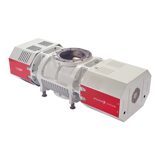
Lubrication is limited to the two bearing and gear chambers which are arranged separately from the suction chambers. Scan the QR code or click here and see how Pfeiffer Vacuum roots pumps work. Fig. 2: HiLobe 14004 design 1 Filler screw... -
Page 18: Cooling
The vacuum pump is suitable for vertical direction of flow. 3.2 Identifying product To ensure unambiguous identification of the product when communicating with Pfeiffer Vacuum, always keep all of the information on the rating plate at hand. The following information is shown on the rating plates: ●... -
Page 19: Transportation And Storage
● Fill the gear and bearing chambers with lubricant only once the final installation posi- tion is reached. Packing Pfeiffer Vacuum recommends storing the transport packaging. Safe transport of the product 1. Observe weight specified on the rating plate. 2. Where possible, always transport or ship the roots pump in its original packaging. -
Page 20: Storing Vacuum Pump
Neither the suction chamber nor the pistons in the roots pump in the roots pump interior are provided with corrosion protection. Storage Pfeiffer Vacuum recommends storing the products in their original transport packaging. Procedure 1. Vacuum-seal both connection flanges. 2. Store the roots pump only in dry, dust-free rooms, within the specified ambient conditions. -
Page 21: Installation
► Install suitable touch protection if the vacuum pump is accessible to untrained persons. ► Allow the vacuum pump to cool down before carrying out any work. ► Contact Pfeiffer Vacuum for suitable touch protection in system solutions. General notes for the installation of vacuum components ►... -
Page 22: Filling With Lubricant
– Only the lubricant used during initial installation is permissible. – D2 is permitted as a replacement for D1. ► Contact Pfeiffer Vacuum if you want to use another type of lubricant. Required consumables ● Lubricant of the vacuum pump Required tools ●... -
Page 23: Connecting Vacuum Side
Installation Fig. 6: Filling with lubricant 1 Filler screws Drain screw 2 Fill level limiter Filling up lubricant The oil chambers of the roots pump are each equipped with a fill level limiter. A riser tube limits the max. fill level. ●... - Page 24 Installation WARNING Risk of crushing from rotating parts Fingers and hands may be caught by rotating pistons within the connection flange. This results in se- vere injuries. ► Keep limbs out of the reach of the roots pump. NOTICE Property damage from intake of solid particles During commissioning, there is a risk of damage to the suction chamber from dirt from the system or the pipes.
-
Page 25: Connecting The Fore-Vacuum Side
● Ring spanner, WAF 16 with flange DN 250 ISO-F ● Ring spanner, WAF 30 with flange DN 250 PN16 Condensate separator Pfeiffer Vacuum recommends installing a condensate separator, with condensate drain at the lowest point of the exhaust line. Connecting the fore-vacuum side 1. -
Page 26: Connecting Gas Temperature Sensor
Installation CAUTION Danger of burns on hot surfaces If the PTC thermistor temperature sensor (PTC) is incorrectly connected, or not connected, the sur- face temperature of the motor rises as a result of an increased winding temperature. ► Always make sure that the PTC is connected correctly. CAUTION Electric shock and damage to the vacuum pump and electronic drive unit due to improper connection and disconnection of components... -
Page 27: Connecting Lubricant Temperature Sensor
Installation G 1/2” Fig. 9: Installation dimensions, gas temperature sensor, fore-vacuum side Connecting gas temperature sensor ► Install the gas temperature sensor on the fore-vacuum connection. ► Connect the connecting cable to the matching connector on the respective control unit. ►... -
Page 28: Connecting Fan
Installation Fig. 10: Installation dimensions, lubricant temperature sensor Connect the lubricant temperature sensor on both sides ► Install the temperature sensors on both oil chambers. ► Connect the connecting cables to the matching connectors on the respective control unit. ► Use the control unit supplied by the customer to evaluate the measured values. ►... -
Page 29: Designing Frequency Converter
Installation Connecting cable Assignment SELV brown (+) 24 V DC 90 W; 3.75 A black (n.c.) n. c. blue (-) Tbl. 7: Pin assignment fan connecting cables Connecting extension cable ► Connect the connecting cables of the two fans to the matching connections on the respective con- trol unit. -
Page 30: Connecting Accessories
– Observe the frequency converter manufacturer's specifications. 5.11 Connecting accessories Installation and operation of accessories Pfeiffer Vacuum offers a series of special, compatible accessories for its roots pumps. ● Information and ordering options for approved accessories can be found online. -
Page 31: Operation
► Install suitable touch protection if the vacuum pump is accessible to untrained persons. ► Allow the vacuum pump to cool down before carrying out any work. ► Contact Pfeiffer Vacuum for suitable touch protection in system solutions. Observe before switching on ●... -
Page 32: Adjusting Sealing Gas Amount
Operation 2...3 sec Fig. 12: Checking direction of rotation with pressure measurement Direction of rotation check One way of detecting the direction of rotation is via a pressure measurement at the roots pump. 1. Close the vacuum flange. 2. Establish the tube connection at the fore-vacuum flange. 3. -
Page 33: Operating Modes
Operation ● Q = Sealing gas flow under standard conditions [Nm ● p = Intake pressure [hPa] ● p = Ambient pressure under standard conditions [hPa] ● ∆p = Differential pressure max. [hPa] ● p = Fore-vacuum pressure [hPa] ● A = Sealing gas content at the operating gas flow (0.01 ≤... -
Page 34: Check The Lubricant Level
Operation Acknowledge error - Query status ► Set up the control unit so that the vacuum pump does not start up automatically after eliminating the fault. ► Set up the control unit so that it actively starts up the vacuum pump after acknowledging the mal- function message. -
Page 35: Maintenance
► Keep limbs out of the reach of the roots pump. NOTICE Danger of property damage from improper maintenance Unprofessional work on the vacuum pump will lead to damage for which Pfeiffer Vacuum accepts no liability. ► We recommend taking advantage of our service training offering. -
Page 36: Changing Lubricant
We recommend that Pfeiffer Vacuum Service (PV) carry out maintenance work at level 3. Pfeiffer Vacuum will be released from all warranty and liability claims if maintenance work is not carried out properly. This also applies wherever parts other than original spare parts are used. -
Page 37: Draining Lubricant
The usable life may deviate from the reference value specified depending on thermic and chemical loads, or due to penetrating process media in gear and bearing chambers. Safety data sheets You can obtain the safety data sheets for lubricants from Pfeiffer Vacuum on request, or from the Pfeiffer Vacuum Download Center. -
Page 38: Filling With Lubricant
Maintenance Draining lubricant Unscrew the fill level limiter To drain the lubricant, in addition to the drain screw, also unscrew the fill level limiter on the pump bottom side. 1. Make sure that there is sufficient space underneath the vacuum pump to place a collection recep- tacle for the lubricant. - Page 39 Maintenance 3. Fill the lubricant on both sides up to the maximum fill level. – Once full, lubricant overfills the fill level limiter, and drips out of the drain hole. 4. Screw the filler and drain screws back in. 39/56...
-
Page 40: Decommissioning
The useful life of the lubricant is limited (max. 2 years). Prior to recommissioning, carry out the follow- ing operations following inactivity of 2 years or more: ► Observe the maintenance instructions – consult Pfeiffer Vacuum where necessary. ► Change the lubricant. -
Page 41: Recycling And Disposal
– Potentially contaminated components that come into contact with media 9.2 Dispose of HiLobe roots pumps Pfeiffer Vacuum roots pumps from the HiLobe series contain materials that you must recycle. 1. Fully drain the lubricant. 2. Disconnect the electronic drive unit. -
Page 42: Malfunctions
● Suction chamber dirty ● Suction chamber dirty ● Switch off the vacuum pump immediately. ● Clean suction chamber. ● If necessary, contact Pfeiffer Vacuum Serv- ice. Vacuum pump rotating in ● Incorrect phase sequence ● Check the phase sequence. -
Page 43: Error Codes
● Clean suction chamber. ● Damage to the bearing or gear ● Switch off the vacuum pump immediately. wheels ● Contact Pfeiffer Vacuum Service. ● Imbalance due to deposits on or ● Clean the pistons. in the pistons Tbl. 10: Troubleshooting 10.3 Error codes... - Page 44 Err# Overload (FC) ● Suction chamber contaminated – Vac- ● Check the vacuum pump uum pump clogged over a longer peri- ● Contact Pfeiffer Vacuum Service od or overloaded ● Observe the intended use ● Short-circuit Err# Excess temperature ●...
-
Page 45: Service Solutions By Pfeiffer Vacuum
We are always focused on perfecting our core competence – servicing of vacuum components. Once you have purchased a product from Pfeiffer Vacuum, our service is far from over. This is often exactly where service begins. Obviously, in proven Pfeiffer Vacuum quality. - Page 46 Service solutions by Pfeiffer Vacuum 5. Prepare the product for transport in accordance with the provisions in the contamination declaration. a) Neutralize the product with nitrogen or dry air. b) Seal all openings with blind flanges, so that they are airtight.
-
Page 47: Ordering Spare Part Packages
► Use only original spare parts. Spare part packages Pump version Order number Maintenance kit 3 HiLobe 14004 PP E42 200 -T Maintenance kit for cleaning suction chamber HiLobe 14004 PP E48 200 -T Tbl. 13:... -
Page 48: Accessories
Accessories 13 Accessories View the line of accessories for Pfeiffer Vacuum roots pumps online at pfeiffer-vacuum.de. 13.1 Accessory information Fixing materials Type-specific assembled packages ensure secure fastening of the vacuum pump. Optionally with splint- er shield or protective screen. Connecting cable Connection and extension cables provide a secure and suitable connection. Different lengths on re- quest. -
Page 49: Tbl. 15: Consumables
Accessories Description Order number F5, Perfluoropolyether, 1 l PK 001 852 -T F5, Perfluoropolyether, 5 l PK 001 853 -T Tbl. 15: Consumables 49/56... -
Page 50: Technical Data And Dimensions
Technical data and dimensions 14 Technical data and dimensions 14.1 General Basis for the technical data of Pfeiffer Vacuum roots pumps ● Specifications according to PNEUROP committee PN5 ● ISO 21360-1: 2016 “Vacuum technology - Standard methods for measuring vacuum-pump per- formance - General description”... -
Page 51: Tbl. 19: Technical Data Hilobe | Vertical Direction Of Flow
Technical data and dimensions Type designation HiLobe 14004 Mounting orientation Vertical, inlet on top Nominal pumping speed 2 700 – 13 540 m³/h Max. permissible pressure differential at max. rotation speed 10 hPa Max. permissible pressure differential at min. rotation speed 30 hPa Emission sound pressure level (EN ISO 2151) at intake pres- <... -
Page 52: Dimensions
Technical data and dimensions 14.4 Dimensions DN 250 PN16 / DN 250 ISO-F M24 - (12x) M10 - (12x) G1/2" (4x) G3/8" (4x) DN 250 PN16 / DN 250 ISO-F 1433 Fig. 15: HiLobe 14004 Dimensions in mm 52/56... -
Page 53: Ec Declaration Of Conformity
DIN EN 60204-1: 2019 DIN ISO 21360-1: 2020 DIN EN IEC 63000: 2019 The authorized representative for the compilation of technical documents is Dr. Adrian Wirth, Pfeiffer Vacuum GmbH, Berliner Straße 43, 35614 Asslar, Germany. Signature: Pfeiffer Vacuum GmbH Berliner Straße 43... -
Page 54: Declaration Of Conformity
ISO 21360-1: 2020 EN IEC 63000: 2018 The manufacturer's authorized representative in the United Kingdom and the authorized agent for compiling the technical documentation is Pfeiffer Vacuum Ltd, 16 Plover Close, In- terchange Park, MK169PS Newport Pagnell. Signature: Pfeiffer Vacuum GmbH Berliner Straße 43... - Page 55 55/56...
Need help?
Do you have a question about the HILOBE 14004 and is the answer not in the manual?
Questions and answers