Table of Contents
Advertisement
Quick Links
Advertisement
Table of Contents

Related Manuals for ePropulsion I-20


Summary of Contents for ePropulsion I-20
- Page 1 I-20 User Manual 2023.04 Version 1.0 Copyright © ePropulsion Technology Limited...
-
Page 3: Acknowledgement
Before use of the product, please read this user manual thoroughly to understand the correct and safe operations. By using this product, you hereby agree that you have fully read and un- derstood all contents of this manual. ePropulsion accepts no liability for any damage or injury caused by operations that contradict this manual. - Page 4 You need to be alert, perform relevant operations reasonably, and pay atten- tion to safety. when installing, operating, maintaining or serving ePropulsion products, there are many safety risks in the process. You need to be alert, perform relevant operations reasonably, and pay attention to safety.
-
Page 5: Product Identification
Product Identification Below picture indicates the serial numbers of the I-20 inboard motor. Please note the position of the serial numbers and record them for access to warranty service and other after-sale services. Product Label... -
Page 6: Table Of Contents
Table of Contents Acknowledgement ....................1 Using This Manual ....................1 Symbols ......................... 1 Product Identification ..................... 3 1 Product Overview ....................7 1.1 In the Package ..................... 7 1.2 Parts and Diagram ..................11 1.3 Specifications .................... 11 1.4 Instructions before Use ................12 2 Unpacking steps and notices ................ - Page 7 4.3.1.2 Installation ................29 4.3.2 Connect the DC-DC module .............. 32 4.3.2.1 Required accessories and tools ..........32 4.3.2.2 Installation ................32 4.3.3 Connect the G102-100 Battery ............33 4.3.3.1 Required accessories and tools ..........33 4.3.3.2 Installation ................33 4.3.4 Connect the DC-DC module to the 12V battery .........
- Page 8 5.6.3 General setting ................56 5.6.3.1 System firmware information ..........56 5.6.3.2 Maintenance - All maintenance timing tips ......57 5.6.3.3 ePropulsion Connectivity Service ......... 58 5.7 Connectivity ....................58 5.7.1 Mobile application ................58 5.7.2 How to connect ................60 5.7.3 OTA update ..................
-
Page 9: Product Overview
If there is any loss or transport damage, please contact your dealer immediately. Items Qty. Figure Function Provide the ship's propulsion, I-20 main part driving the ship. Transfer the electrical energy of the power supply from the Bus bar main circuit of the power supply system to different components or modules in the circuit. - Page 10 页 加工余量 N10074 机型 页 面 广东逸动科技有限公司 fixing and locking the bus bar 单位:mm Guangdong ePropulsion Technology Limited N10024 完成日期 2023/4/9 Hex wrench The 5mm wrench is used for fixing and locking the DC-DC 1. 4 cross groove outer hexagonal flange tapping 1.
- Page 11 Other accessories not included in the package are also required to operate the outboard motor, such as smart throttle, smart display, battery, charger and communication cable, etc. Users can buy official accessories provided by ePropulsion from ePropulsion authorized dealers. The accessories list is shown below: Items Qty.
- Page 12 未注尺寸公差 比例 未注几何公差 重量 共 页 第 页 加工余量 N10074 机型 页 面 广东逸动科技有限公司 Guangdong ePropulsion Technology Limited N10024 完成日期 2023/4/12 单位:mm Provide electrical energy 12V battery for the system's 12V power requirements equipment 3.3kW charger Charge the G102 battery...
-
Page 13: Parts And Diagram
12V power cable 5m High voltage power cable 2m Figure 1-1 1.3 Specifications Input power 20kW Recommended battery ePropulsion Lithium Iron Phosphate Battery 86~115V (high voltage); Input voltage range 9V~16V (low voltage) Rated output torque 140N.m Weight 49.5kg Dimensions (L*W*H) -
Page 14: Instructions Before Use
1.4 Instructions before Use 1. Only adults who have fully read and understood this manual are allowed to operate this product. Read the full user manual carefully before operation, ePropulsion accepts no liability for any damage or malfunction caused by operations violating this manual. - Page 15 7. Check before each trip if there is enough safety equipment including but not limited to enough life jackets, personal flotation devices, fire extinguishers, bells and whistles, communication equipment, and paddles, etc. Check available local boating safety requirements before operating. 8.
-
Page 16: Unpacking Steps And Notices
2 Unpacking steps and notices 2.1 Safety Notice Use appropriate safety equipment, wear gloves, protection shoes and other safety props; Ensure that all safety and measures are understood before operation; Due to the large weight of the product, ensure that at least two people operate; 2.2 Tools and equipment required for unpacking Prepare unpacking tools, such as rubber hammer, screwdriver, etc. -
Page 17: Remove The Inner Packaging And Inspect The Product
4. Take out CAN communication extension cable, CAN communication cable, main power cable, check whether the appearance is abnormal; 5. Sort out the motor, accessories, packaging and other related materials. Check the product for broken or missing parts, if there is a problem, please contact ePropulsion after-sales service for help. -
Page 18: Dispose Of Discarded Packaging Materials
2.6 Dispose of discarded packaging materials 1. Classify and recycle packaging materials, such as wood, paper, etc. 2. Follow local environmental regulations to dispose of waste materials. Make sure to read the user manual that come with the product carefully. Please follow the local material handling requirements to recycle the package, reasonable disposal, to protect the environment. -
Page 19: Install The I-10 Motor
3.1.1 Before installation 1. Check the materials: ① Motor: Check the I-20 machine structure to ensure that there is no loosening or abnormality. Arrange the main power cables, 12V power cable, and communication cable and fix them in appropriate positions for easy handling. - Page 20 Suggestions for the mounting platform: First, design the proper mounting platform according to the size model of the motor, the space inside the ship and the position of the stern shaft. The size of the fastening hole of the mounting platform is M10, and the size distribution is determined according to the position of the fixing hole of the suspension support foot.
-
Page 21: Center The Output Shaft
Lifting objects hazard: pay attention to safety when hoisting equipment or objects nearby to avoid being hurt or crushed by falling objects. 88mm 100mm The cover shall be installed after the 4G antenna is installed. 3.1.2 Center the output shaft 1. - Page 22 3. Move the motor so that the output shaft flange of the motor is close to the input shaft flange of the stern shaft, align the input shaft flange of the stern shaft, and compare the height difference between the output shaft and the input flange of the stern shaft. Adjust the suspension height, the ship machine shaft flange and the stern shaft input flange to adjust to the same height;...
-
Page 23: Lock The Output Shaft And Fix The Suspension
5. Flange surface fitting, flush the outlet flange with the stern shaft input flange end face, so that the positioning boss is embedded in the output shaft flange, so that the two flange faces fit, observe the size of the gap. (Note: pay attention to the mounting position of the suspension simultaneously) Positioning boss Positioning boss... - Page 24 13mm Caution: when installing, operating, maintaining or serving ePropulsion products, there are many safety risks in the process. You need to be alert, perform relevant operations 86mm 90mm reasonably, and pay attention to safety.
-
Page 25: Connect Seawater Inlet And Outlet Pipes
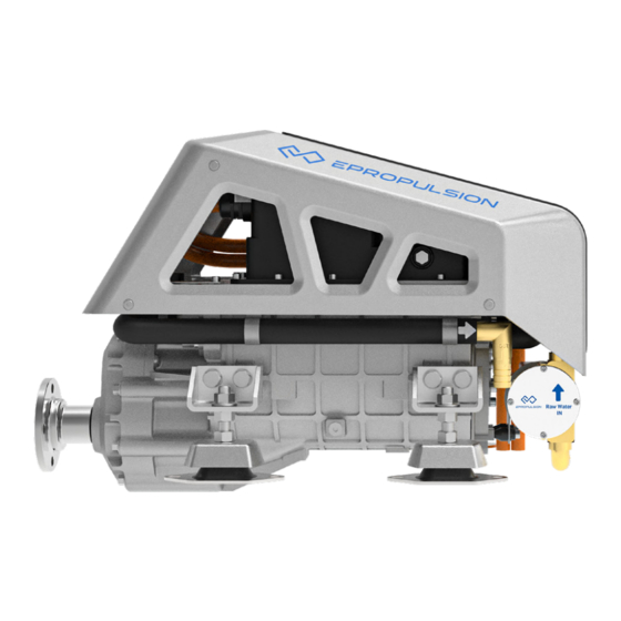
3.2 Connect seawater inlet and outlet pipes The machine has a water pump. According to the logo in the above figure, the water pipes with an inner diameter of 19mm are selected to be connected to the water inlet and the water outlet respectively, and the water pipes are fixed on the pagoda joint with clamps. -
Page 26: Connect The System Before Operating The Machine
4 Connect the system before operating the machine 4.1 System connection diagram 4.1.1 System connection diagram of the single-motor 1. CAN Comm extension cable 10. Battery to bus bar power cable 2. 5-way T connector 11. Charger output power cable 3. -
Page 27: System Connection Diagram Of The Dual-Motor
4.1.2 System connection diagram of the dual-motor 1. For dual-motor with a 12V battery 1. CAN Comm extension cable 10. Battery to bus bar power cable 2. 5-way T connector 11. Charger output power cable 3. 3-way T connector 12. Bus bar to DC-DC power cable 4. - Page 28 2. For dual-motor with two 12V batteries 1. CAN Comm extension cable 10. Battery to bus bar power cable 2. 5-way T connector 11. Charger output power cable 12. Bus bar to DC-DC power cable 3. 3-way T connector 4. Communication terminator 13.
-
Page 29: Notes
4.1.3 Notes 1. Do not cover the 4G antenna and GPS module to avoid wireless signal attenuation. 2. When using batteries, make sure the main switch is off before connecting. 3. Users can also connect multiple batteries in parallel to expand battery capacity. For details about battery usage and notices, refer to the G102 battery user manual. - Page 30 The section structure of the cable is shown in the figure above. ① Outer sheath; ② metal shielding layer; ③ inner sheath; ④ copper core conductor (2) Use a wire stripper to strip the length of the " ① outer sheath" by 20mm(+5,-0)mm. The cable Aater peeling off the outer sheath is shown below: (3) Use a scissor to cut 10mm(+5,-0)mm of the exposed "...
-
Page 31: Cable Connection
(6) Cover the heat shrink tube Cut the length of 60-100mm heat shrink tube (red and black), refer to the color of the existing heat shrink tube at the end of the cable, put the red and black heat shrink tube on the corresponding cable respectively (red-red, black-black corresponding set), put the cable lug and the cable "... - Page 32 (1) Remove the screws and top cover of the bus bar with an M4 socket wrench Figure 4-1 The disassembled bus bar (2) Install the cable lug of 4 groups of cables It is necessary to install 4 groups of cables ( ② , ③ , ④ and ⑤ ) of 4.3.1.1, a total of 8 cables to the terminals on the top.
- Page 33 3. After installing the positive cable, install and lock the positive and negative baffles with screws; 4. Install the negative cable (black sleeve) on the upper copper bar, the locking torque of M6 nut is 5N·m, the locking torque of M8 nut is 10N·m, ② connect MOT-, ③ connect BAT-, ④ connect 96V-2- and ⑤...
-
Page 34: Connect The Dc-Dc Module
4.3.2 Connect the DC-DC module 4.3.2.1 Required accessories and tools ① The part of the bus bar completed in Step 4.3.1 ② Phillips Screwdriver ③ DC-DC to 12V battery power cable 4.3.2.2 Installation (1) Connect the bus bar to the DC-DC module Remove the transparent protective cover of the DC-DC terminal. -
Page 35: Connect The G102-100 Battery
4.3.3 Connect the G102-100 Battery 4.3.3.1 Required accessories and tools ① G102-100 battery ② The bus bar connected in Step 4.3.1 4.3.3.2 Installation (1) Connect the bus bar to the G102-100 battery Plug the aviation plug of the bus bar portion into the corresponding color port on the G102- 100 battery. -
Page 36: Connect The Power Cable Of The Motor Of The Ship
4.3.5 Connect the power cable of the motor of the ship 4.3.5.1 Required accessories and tools ① Motor ② The connection of the bus bar, DC-DC module, 12V battery completed in step 3.3 ③ M8 hex socket screws and nuts ④... - Page 37 Press down on the black handle, using the black handle to make the connector fit tightly and close the latch, as shown below. Figure 4-10 High Voltage Interlock Plug (2) Connect the 12V power cable Connect the red and black wires drawn from the machine to the positive pole of the 12V battery according to the red cable, and the black cable to the negative pole of the 12V battery, and connect to the 12V battery terminal post, and lock the terminal post nut.
-
Page 38: Connect Interactive Devices And Accessories
4.3.6 Connect interactive devices and accessories (Smart throttle, smart display, external GPS module, 4G antenna, G102-100 battery) 4.3.6.1 Required accessories and tools ① Smart throttle ×1; ② Smart display ×1; ③ External GPS module ×1; ④ G102-100 battery ×1; ⑤ Communication cable ×3; ⑥... - Page 39 After the interactive device is connected, the thread of each connector should be tightened to ensure stability and waterproof. (3) Connection of smart throttle BUS port and DUAL port are at the bottom of smart throttle. Connect to the other throttle and use as dual-throttle Connect to system The cable connections for specific application scenarios are as follows:...
- Page 40 If the cover has been removed when hoisting, then this step can be ignored. 2. Connect the SMA male at the end of the 4G Antenna to the corresponding interface of the drive module, and install the I-10 cover after confirming tightening; Driver module SMA female 4G antenna...
- Page 41 3M adhesive stick fixed Glue the sealing cover plate fixing adhesive of the accessories to the specified area at the bottom of the GPS external module, and paste it in an open outdoor area. Before pasting, ensure the cleanliness of the pasting position to avoid improper pasting due to impurities at the pasting position.
-
Page 42: Connection Of Communication Terminator
4.3.7 Connection of communication terminator In the process of using the onboard machine, in order to make the communication between the various components more stable, it is necessary to connect different combinations of end point resistors on the T-connector combination according to the following scenarios. The end point resistance value is marked at the tail of the end point resistance, as shown in the figure: (1) Single-machine Please connect a communication terminator marked "120Ω"... -
Page 43: Status After Connection
4.3.8 Status after connection It is recommended to place each module in the actual installation position on the ship before connecting the cable. The cable marked as "1", "2", "3" and "4" in Figure 15 can be properly expanded or coiled according to the actual position and distance of each module. The part labeled "1"... -
Page 44: Operation
5 Operation 5.1 Smart Throttle Button Description Single-throttle operation Button Function Power on and off the system: When the motor is turned off, long press the Power button for 1 second to start the motor. When the system is turned on, long press the Power button for 1 second to Power stop the motor. - Page 45 Dual-throttle operation Button Function Power on and off the system: When the motor is turned off, long press the Power button for 1 second to start the motor. When the system is turned on, long press the Power button for 1 second to Power stop the motor.
-
Page 46: Smart Throttle Button Description
Note: The kill switch is placed correctly. Please place a kill switch on either side of the Smart Throttle to start the motor. Please remove the kill switch after the machine is turned off. Stop the inboard motor in emergency by detaching the kill switch. To run the motor again, first attach the kill switch, then start the motor. - Page 47 Step 2: Configure the location of the equipment When there is only one console and one propulsion, the system will automatically complete the system initialization settings and directly enter the home page. When there are more than one console and more than one propulsion, the user needs to configure the console accessories and the position of the propulsion.
- Page 48 When it is a single-throttle, manually click any button of the throttle to match successfully. When it is a dual-throttle, click any button of the left and right throttles respectively to match successfully. 3. After console A is configured, the remaining parts will be automatically matched to console B.
-
Page 49: Home Page
5.4 Home Page Function Description Setting page Click to go to the setting page. Home page Click to go to the home page. Propulsion page Click to go to the propulsion page. When the system fails, it will prompt a fault icon, Warning with the number representing the number of faults. - Page 50 Function Description Battery indicator bar The indicator changes with battery level. Battery level Battery level The remaining distance/time supported by the Remaining distance or time current battery level. You can switch between distance and time in the settings. Compass When it reach the rated power, it is full grid. The Power indicator indicator will change accordingly when the power changes.
-
Page 51: Powertrain Diagram
5.5 Powertrain diagram 5.5.1 Control console Click on the console to view the accessories for each console. -
Page 52: Power Battery
When the accessories fail, the icon will turn orange or red. Click the fault icon to view the detailed fault. 5.5.2 Power Battery The power battery can be clicked to view the remaining power, voltage, and current. -
Page 53: Propeller
5.5.3 Propeller Motors can be clicked to view current power, rotational speed and accumulated running time since the last maintenance. 5.6 Setting The Settings include three major module Settings: motor Settings, control console Settings, and general Settings. -
Page 54: Propulsion Setting
Button Function Click to enter the propulsion setting page, you can set the motor INBOARD switch and reverse propeller switch. Click to enter the console setting page, you can set single-throttle CONTROL assembly, dual-throttle FN function, Smart display, etc. GENERAL Click to enter the general setting page to set firmware update, maintenance, connectivity and more. -
Page 55: Control Console Settings
5.6.2 Control console Settings 5.6.2.1 Smart throttle settings 1. Single-throttle Settings Button Function Click and set the smart throttle installation mode to starboard Starboard installation. If it springs back, the setting fails. Click and set the smart throttle installation mode to port installation. Port If it springs back, the setting fails. - Page 56 2. Set dual-throttle Button Function None Set the FN function of smart throttle as invalid after clicking. Set the FN function of smart throttle to sync left and right handle after clicking. When the throttle values of the left and right throttle are not much Sync different, the system will forcibly synchronize the throttle values of the two sides into one value.
-
Page 57: Display Settings
Motor output indication home page will change accordingly after the switch. The unit can be switched between knot, km/h and mile/h. After the Unit switch, the speed limit unit of the home page and ePropulsion setting page will be changed accordingly. -
Page 58: General Setting
5.6.3 General setting 5.6.3.1 System firmware information Button Function System version Display the propulsion version. Click Device List to go to the device serial number list page. You can Serial number view all device SN and software and hardware version. When there is a new version to be updated, you will be prompted with the content of the new version and the estimated time. -
Page 59: Maintenance - All Maintenance Timing Tips
Device list page 1. Click Reset to reset the device to its factory device state. 2. Device List displays the SN and software and hardware versions of all components of the propulsion. 5.6.3.2 Maintenance - All maintenance timing tips 1. The period of maintenance is 220 hours and the system will automatically calculate the maintenance countdown based on the accumulated running time since the last maintenance. -
Page 60: Epropulsion Connectivity Service
5.6.3.3 ePropulsion Connectivity Service Register in the ePropulsion Link account with your mobile phone, and when you add a new boat, you can scan the code to bind the power system. ePropulsion Link is a software product developed by ePropulsion, which provides shipowners with major functions such as boat status monitoring, voyage log management and firmware upgrades. -
Page 62: How To Connect
5.7.2 How to connect 1. Log in to the websites. a. ePropulsion Link: https://link.ePropulsion.com b. ePropulsion Fleet: https://fleet.ePropulsion.com 2. Sign up for your account. a. Click the Sign Up button to sign up for your account b. Please use your usual email address to register, so that you can retrieve your password if you forget it. - Page 63 After logging in to the home page for the first time, click Create Boat button to enter relevant information (Boat Name, Boat Brand, Model, Registration Number). Boat Name is mandatory. Before creating boats in ePropulsion Fleet, it is necessary to create a fleet first, which can be completed according to the App prompts.
- Page 64 After the connection is successful, you will see a prompt indicating that the connection has been successful and can see information such as the current boat's location and power level. You can use the Add to Home Screen feature for iOS and Android systems to pin the Bookmark to the first screen for quick access.
-
Page 65: Ota Update
1. Receive OTA notification a. The display will receive OTA update notifications with the ePropulsion Link as well as the ePropulsion Fleet. b. The ePropulsion Link and ePropulsion Fleet will be notified of OTA updates on the Notifications page. -
Page 66: Motor Operation
3. Complete OTA update a. After the binding is successful, you will see a message indicating that the binding is successful. You can also see that the current software version is the latest version on the user's software and display. (1). -
Page 67: Stop
Neutral Forward Neutral Forward Backward Backward Port Starboard 5.8.3 Stop This product can be stopped in one of four ways 1. Turn throttle to zero position. 2. Remove the Kill Switch. 3. Switch off the power button. 4. Disconnect the power cable. 5.8.4 Notices 1. -
Page 68: Troubleshooting
2. Rotating parts can cause severe injury or death. Never wear jewelry, unbuttoned cuffs, ties or loose-fitting clothing and always tie long hair back when working near moving/ rotating parts such as the flywheel or PTO shaft. Keep hands, feet and tools away from all moving parts. -
Page 69: System Faults
5.9.2 System faults Module Fault Solution 1. Check the external wiring. Encoder fault P101003 2. Replace the rotary encoder. 3. Replace the motor controller. 1. Check the external wiring. Power tube pass- P100F03 2. Check the insulation of the motor. through failure 3. - Page 70 Module Fault Solution The generator is generally P100912 Check the battery SOC undervoltage 1. Check the operating condition. The MOS 2. Check whether the heat dissipation is severely P100003 channel is blocked. overtemperature 3. Check the coolant level 1. Overhaul the motor or transmission The motor system.
- Page 71 Module Fault Solution 1. Do not need to be processed if it is recoverable CAN_B BUSOFF P130941 2. Check whether the cable is in poor contact 1. Do not need to be processed if it is recoverable CAN_C BUSOFF P130A43 2.
- Page 72 Module Fault Solution 1. Recalibrate away from strong Abnormal throttle magnetic fields H120203 calibration data 2. If it occurs repeatedly, contact after- sales treatment Abnormal throttle Smart throttle H120003 Stay away from strong magnetic fields Angle Abnormal safety Check that the safety switch is properly H120403 switch sucked into the slot...
-
Page 73: Maintenance
6 Maintenance 6.1 Repair and maintenance: Maintenance cycle Every interval First maintenance thereafter Components Items Work 50 hours 100 hours 250 hours 1000 hours (or 3 (or 6 (or 1 year) (or 4 years) months) months) Suspension Foot pads of repair and Check/Replace suspension... -
Page 74: Part Of The Repair And Maintenance Guide
页 第 页 机型 N10074 1 00 页 面 加工余量 广东逸动科技有 Guangdong ePropulsion Techno N10074 机型 单位:mm N10024 完成日期 2023/4/1 页 面 广东逸动科技有限公 3. Check the O-ring and new impeller on the pump casing for damage (if any, it needs to be Guangdong ePropulsion Technology 单位:mm... -
Page 75: Regular Cleaning Of Heat Exchanger
Please pay attention to the placement of the container to prevent the coolant from leaking and polluting the environment. 3. Use the movable wrench to remove the I-20 vent pipe on the gearbox (be careful not to scratch the sealing ring of the I-20 vent pipe);... - Page 76 8. Install the external circulation water pipe to the pagoda head of the heat exchanger, and lock the adjustable clamp; 9. Tighten the I-20 vent pipe with a movable wrench, and pay attention not to press the sealing ring of the I-20 vent pipe during installation;...
-
Page 77: List Of Fasteners
6.3 List of fasteners Assembly to be Locking reference Items Specifications fastened moment (Nm) Hex socket flat head Cover M5x12 1.5~2.0 screw Hex socket round head Deflector series M5x10 1.5~2.0 screw Hex socket round head Fan fasteners M5x10 1.5~2.0 screw Suspension foot Hexagon bolt M10×18... -
Page 78: Warranty
(the “ePropulsion Service Partners”) with minimum maintenance charge per occurrence. In all warranty cases, ePropulsion will only bear the repair cost and other costs (such as those related to product installation, disassemble, transportation, financing, rental, etc.) as a direct result forof issues covered by the Limited Warranty only. -
Page 79: Out Of Warranty
The Limited Warranty may change from time to time. Pls visit our website (http://www.epropulsion.com) for the latest version. 7.1 Out of Warranty ePropulsion may refuse a warranty claim if: • Any improper operation contradicts what is written in the user manual; • Accident, misuse, dropping, improper care or storage, willful abuse, physical damage, overcharging, over discharging, or unauthorized repair;... -
Page 80: Limited Warranty Claim Procedures
6. In case your warranty claim be rejected, a repair/replace cost and fee with round trip delivery cost will be estimated and sent to you for confirmation. ePropulsion Service Partners will only begin the work after your written confirmation. - Page 83 WARRANTY CARD ePropulsion Control System (*In order to validate warranty, please fill in this form first and read the Warranty Policies.) OWNER INFO. Owner Name Address Email Phone DEALER INFO. Store Name Address Email Phone PRODUCT INFO. Date of Purchase (mm/dd/yyyy)
- Page 84 Thanks for reading this user manual. If you have any concerns or find any problems while reading, please don't hesitate to contact us. We are delighted to offer service for you. Guangdong ePropulsion Technology Limited Webseite: www.epropulsion.com E-Mail: service@epropulsion.com...
Need help?
Do you have a question about the I-20 and is the answer not in the manual?
Questions and answers