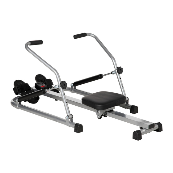
HOMCOM A90-276 Assembly & Instruction Manual
Hide thumbs
Also See for A90-276:
- Assembly & instruction manual (17 pages) ,
- Assembly instruction manual (18 pages)

Related Manuals for HOMCOM A90-276


Summary of Contents for HOMCOM A90-276
- Page 1 INapa013_IT_EN A90-276 IMPORTANT, RETAIN FOR FUTURE REFERENCE: READ CAREFULLY ASSEMBLY & INSTRUCTION MANUAL...
- Page 2 VISTA ESPLOSA – DIAGRAMMA DI ASSEMBLAGGIO...
- Page 3 LISTA PARTI NOME QTA’ Montante principale Traversa posteriore Bulloni di fissaggio (M8 x 50 mm) Tappo di gomma posteriore Bullone cieco Disco puleggia Sedile Sedile Cacciavite (1/4’’ x ½’’) Tubo di supporto destro Tubo di supporto sinistro Bulloni (M8 x 55 mm) Disco puleggia Due dadi di sicurezza Bullone cieco...
- Page 4 LISTA VITERIA & STRUMENTI Bulloni bulloni di supporto Bulloni (8x50mm) (M8x55mm) (M10x45mm) Bulloni Vite Vite Due dadi di sicurezza (10x55mm) (1/4’’x1/2’’) (M4x16mm) (M10mm) Dado Disco puleggia rondella in plastica Rondella di plastica (1/2’’)
- Page 5 ASSEMBLAGGIO Passo 1: Fissare il sedile tramite 4 viti (parte 9) al supporto del sedile come mostrato in figura seg- uente. L'estremità più spessa del sedile deve essere rivolta verso l'estremità posteriore del vogatore. Passo 2: Fissare il tubo di supporto sinistro (10b) e destro (10a) al montante principale (parte 1) e avvitare questi supporti (parte 10a e 10b) con due viti a sei bulloni (parte 11), ogni set con due rondelle (parte 12) e due dadi di sicurezza (parte 13) come mostrato in figura seg- uente.
- Page 6 Passo 3: Spingere il pedale con il supporto per poggiare i piedi attraverso i fori del montante. Quindi spingere un tappo di plastica (Parte 15), il supporto (Parte 16) e una rondella di gomma (parte 17) sul montante e avvitare con l'aiuto del secondo dado grande (parte 18). Passo 4: Collegare il montante destro del vogatore (parte 19a) con la staffa laterale destra (parte 19a);...
- Page 7 Passo 5: Stringere la vite di fissaggio (parte 27) nel morsetto ad H (parte 26) e un disco puleggia (parte 12) sul montante destro del vogatore (19a) e stringere la vite. Ripetere questa operazione sull'altro lato (19b). I due morsetti ad H devono essere alla stessa altezza rispettivamente sui montanti sinistro e destro.
- Page 8 COMPUTER Dopo aver inserito la batteria (2 batteria AAA da 1,5 V), lo schermo si illumina e scorre brevemente tutte le opzioni di visualizzazione. Assicurati di inserire la batteria con la corretta polarità registrata. I fili di contatto devono toccare i poli per una facile alimentazione. ATTENZIONE: Se non vengono visualizzati dati a schermo dopo aver inserito corretta- mente la batteria, rimuovere nuovamente la batteria e reinserirla dopo un’attesa di circa 15 secondi come descritto sopra.
- Page 9 Valori totali [T.CNT] Il totale integrato conta il numero ripetizioni da 0 a 9.999 dall'ultimo inserimento delle batterie all'inizio dell'allenamento. Questo contatore può essere azzerato solo rimuovendo le batterie. Calorie [CAL] Il conta calorie integrato conta fino a 9.999 cal consumate dall'inizio dell'allenamento. Questo valore è...
- Page 10 EXPLODED-VIEW ASSEMBLY RAWING...
-
Page 11: Parts List
PARTS LIST NAME Core Rear cross bar Fixing bolts (M8 x 50 mm) Rubber cover for rear Endstops Disc Seat Seat Screwdriver (1/4’’ x ½’’) Frame tube right Frame tube left Bolts (M8 x 55 mm) Disc Safety Nut Endcap Plastic Pedal support Rubber... -
Page 12: Hardware & Tools List
HARDWARE & TOOLS LIST Bolts Carriers Bolts (8x50mm) (M8x55mm) (M10x45mm) Bolts Screw Screw Safety Nut (10x55mm) (1/4’’x1/2’’) (M4x16mm) (M10mm) Plate disc Rubber washer Plastic (1/2’’) - Page 13 ASSEMBLY Step 1: Attach the seat by means of 4-screw screws (Part 9) to the seat holder as shown below. The thicker end of the seat should point to the rear end of the rowing machine. Step 2: Attach the left (10b) and the right (10a) connecting rod to the main tube (Part 1) and screw these connecting rods (Part 10a&...
- Page 14 Step 3: Push the pedal rod with the attached foot support through the holes in the main frame. Then push a plastic bucket (Part 15), the second base (Part 16) and a rubber disc (Part 17) onto the spindle and screw it with the help of the second big nut (Part 18). Step 4: Connect the right rudder arm (part 19a) with the right side bracket (part 19a);...
- Page 15 Step 5: Attach the fixing screw (part 27) with the help of the H-clamp (part 26) and a disc (part 12) to the right rudder arm (19a) and tighten the screw. Repeat this working step for the rudder arm on the other side (19b). Imagine r that the two H-clamps are on the rowing arms at the same height.
- Page 16 COMPUTER After inserting the battery(2 chunk AAA 1,5V battery), the display lights up and briefly examines all display options. Make sure you insert the battery with the correct recorded polarity. The contact wires must touch the poles for an easy power supply. WARNING: If the display does not show after inserting the correct battery, remove the battery again and place after a waiting period of approximately 15 seconds as described above.
- Page 17 Total Number [T.CNT] The integrated total countes the number of rwoing trains from 0 to 9.999 since the last time the batteries were inserted from the begining of the training. This counter can only be reset to 0 by removing the batteries. Calories [CAL] The integrated calorie counter counts up to 9.999 cal from the start of the training.
Need help?
Do you have a question about the A90-276 and is the answer not in the manual?
Questions and answers