
Related Manuals for HOMCOM A90-275


Summary of Contents for HOMCOM A90-275
- Page 1 INapa006_FR_EN A90-275 IMPORTANT, RETAIN FOR FUTURE REFERENCE: READ CAREFULLY ASSEMBLY & INSTRUCTION MANUAL...
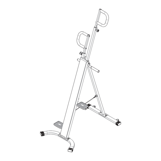
- Page 2 GRAPHIQUE ÉCLATÉ...
-
Page 3: Liste Des Pièces
LISTE DES PIÈCES La liste de pièces suivante décrit toutes les pièces illustrées sur le graphique éclaté de la page suivante. Veuillez noter que la plupart de ces pièces sont déjà préassemblées sur votre appareil. Description Description Stabilisateur avant Bague carrée □38 à □30 Cadre avant Bague carrée □30 à... -
Page 4: Liste Du Matériel
LISTE DU MATÉRIEL Le matériel suivant est utilisé pour assembler votre unité. Veuillez prendre un moment pour vous familiariser avec ces éléments. Veuillez noter que certains de ces éléments sont déjà préassemblés sur la machine. Ne vous inquiétez pas si vous voyez sur cette page des pièces qui ne seraient pas incluses dans votre paquet de matériel. -
Page 5: Instructions D'assemblage
INSTRUCTIONS D'ASSEMBLAGE Étape 1 1. Retirer (#15) 2. Ouvrez (#02) et (#03) 3. Remettre en place (#15) Étape 2 Fixez (#01) à (#02) avec deux (#45), deux (#46), deux (#47). Fixez (#04) à (#03) avec deux (#45), deux (#46), deux (#47). - Page 6 INSTRUCTIONS D'ASSEMBLAGE Étape 3 Insérez les deux (#05) dans les positions correspon- dantes à (#03) respectivement. Étape 4 Connectez le fil de connexion (#16A) au fil sur (#16B).
- Page 7 INSTRUCTIONS D'ASSEMBLAGE Étape 5 1. Insérez (#11L) et (#11R) dans la position correspondante au-dessus de (#02). ***Attention ! La position montrée sur la photo, (#11L) a un aimant (#16C).*** 2. Déplacez (#19) avec votre main comme indiqué, remarquez le trou fileté qui est vide ici, ciblez (#11R) et (#06), verrouillez-les avec un (#49).
- Page 8 INSTRUCTIONS D'ASSEMBLAGE Étape 6 Placez (#08R) dans la position correspondante de DROITE (#06) sur le côté droit, puis alignez les deux trous, verrouillez-les avec deux (#50). Placez ensuite (#08L) dans la position correspondan- te de (#06) sur le côté gauche, puis alignez les deux trous et verrouillez-les avec deux (#50).
- Page 9 INSTRUCTIONS D'ASSEMBLAGE Étape 8 Prendre deux (#13) dans les positions correspondantes de deux (#12) respectivement, les verrouiller avec deux (#47), deux (#48) respectivement. *** L'ASSEMBLAGE est terminé***...
- Page 10 AUTRES Vous pouvez le plier comme indiqué sur le schéma. 1. Retirer (#15) 2. Rabattre (#02) et (#03) 3. Remettre en place (#15) La machine a une fonction mobile. Vous pouvez la déplacer comme indiqué sur la représentation graphique.
-
Page 11: Spécifications
AUTRES BOUTON FONCTIONNEL : MODE/RESET – Appuyez sur ce bouton pour sélectionner les fonctions. – Appuyez vers le bas pour remettre à zéro le temps, le compte et les calories pendant 4 secondes. FONCTIONS ET UTILISATIONS : 1.SCAN : Balayage automatique des fonctions de temps, de comptage total et de calo- ries, chaque affichage sera maintenu 6 secondes 2.TEMPS : Accumule automatiquement le temps d'entraînement lors de l'exercice. -
Page 12: Exploded Diagram
EXPLODED DIAGRAM... -
Page 13: Parts List
PARTS LIST The folowing parts list describes all of the parts illutrated on the exploded diagram on the following page. Please note, most of these parts are already pre-assembled on your unit. Description Description Front stabilizer Square bushing □38 to □30 Front frame Square bushing □30 to □20 Rear frame... -
Page 14: Hardware List
HARDWARE LIST The following hardware is used to assemble your unit. Please take a moment to familiarze yourself wth these items. Please note some of tis hardwar is aready pre-assembled on the machine. Do not be alarmed if you see parts on this page that are not included in your hardware packet. - Page 15 ASSEMBLY INSTRUCTFIONS Step 1 1.Pull out (#15) 2.Open (#02) and (#03) 3.Insert (#15) back Step 2 Secure (#01) to (#02) with two (#45), two (#46), two (#47) . Secure (#04) to (#03) with two (#45), two (#46), two (#47) .
- Page 16 ASSEMBLY INSTRUCTFIONS Step 3 Insert the two (#05) into the corresponding positions at (#03) respectively. Step 4 Connect the Connecting wire (#16A) to the wire on (#16B).
- Page 17 ASSEMBLY INSTRUCTFIONS Step 5 1. Insert (#11L) and (#11R) into the corresponding position above (#02). ***Attention! The position shown in the picture, (#11L) has a magnet (#16C).*** 2. Move (#19) by your hand as shown, see the threaded hole that is empty here, aim at (#11R) and (#06).
- Page 18 ASSEMBLY INSTRUCTFIONS Step 6 Put (#08R) in the corresponding position of (#06) at right side, then align the two holes, lock them with two RIGHT (#50). Then put (#08L) in the corresponding position of (#06) at left side, then align the two holes,lock them with two (#50).
- Page 19 ASSEMBLY INSTRUCTFIONS Step 8 Take two (#13) in the corresponding positions of two (#12) respectively, lock them with two (#47), two (#48) respectively. ***The assembly is completed***...
- Page 20 OTHERS You can fold it as shown in the diagram. 1. Pull out (#15) 2. Close (#02) and (#03) 3. lnsert (#15) back The machine has a movable function. You can move it as shown in the diagram.
-
Page 21: Functional Button
OTHERS FUNCTIONAL BUTTON: MODE/RESET – Push down to select functions. – Push down to reset time、count and calories for 4 seconds. FUNCTIONS AND OPERATIONS: 1. SCAN: Automatically scan functions of time、count、total count and calories, each display will be hold 6 seconds. 2.
Need help?
Do you have a question about the A90-275 and is the answer not in the manual?
Questions and answers