Advertisement
Quick Links
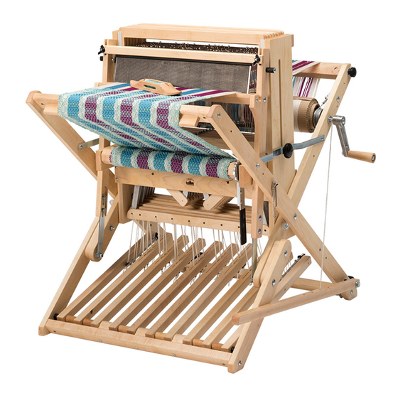
WOLF PUP 8.10 LOOM
A
D
ssembling
BEFORE YOU BEGIN
■ Read through the directions before starting to assemble your
loom.
■ You'll find a complete labelled diagram of the Wolf loom in your
Maintenance and Warranty manual and at schachtspindle.com.
■ Wolf loom legs are called out by where they cross each other.
The legs that touch the ground at the front of the loom are called
"inside" legs because they are covered by the "outside" legs when
they cross at the loom center.
■ The beater is at the front of the loom. The brake is on the right
side of loom.
■ All wooden parts of the loom have been finely sanded and
finished with hand-rubbed Danish oil. From time to time, you may
wish to apply more finish to the loom. Use a Danish oil (tung oil and
polyurethane mixture) and hand-rub the wood with a soft lint-free
cloth. Be sure to follow the finish manufacturer's instructions.
TOOLS
#2 Phillips screwdriver
slotted (flat) screwdriver and/or masking tape
adjustable wrench or wrenches in the following sizes:
5/16", 7/16", 3/8", 1/2"
COMMON HARDWARE
These drawings are not to scale and hardware is not shown in
every size listed.
■ Screws and bolts are sized in inches, measured by shaft
length. Measure the shafts of screws and bolts with a metal tape
measure or the ruler on this page. First identify all the screws and
bolts in a bag, then it will be easier to identify any nuts.
■ Nuts attach to carriage bolts and machine screws. They have
to match the bolt or machine screw in diameter and thread
size. Match the numbers at the beginning of the description (for
instance, 10-24 or 1/4-20) to the corresponding bolt or machine
screw.
■ Washer sizes refer to the diameter of the hole; measure
the hole with a metal tape measure or the ruler on this page. The
washers shown below are all the same size, but they are different
types. For the same size washer, SAE washers have the smallest
outside diameter, fender washers have the largest outside
diameter, and USS washers are in the middle.
For more help identifying hardware, see our guide at
www.schachtspindle.com/pdfs/schacht-hardware-guide.
pdf.
Find out more at schachtspindle.com
Schacht Spindle Company 6101 Ben Place Boulder, CO 80301
303.442.3212
© 2023 Schacht Spindle Company, Inc.
l
isAssembleD
TM
ooms
■ Unpack the loom parts carefully and compare them to the
drawings on pages 2–5. Do not throw away the carton or any of the
packing material until you have checked to see that all of the parts
and hardware bags have been included.
■ Hardware for your loom has been packed into bags for different
steps in the assembly process. Open each bag only when you reach
those steps, then identify the pieces included in that bag.
■ Follow the exact order of assembly. Take care and work slowly. It
will be easier to assemble your loom with a helper. Some steps may
require two people.
■ When you finish assembling the loom, go back over all of the
screws and make sure they are tight. For screws on parts that need
to pivot, tighten the screw firmly, then unscrew just enough to allow
free movement. It is a good idea to re-tighten all screws on your loom
every few months.
carriage bolt
Phillips truss head
sheet metal screw
IDENTIFYING SCREWS AND BOLTS
barrel nut
lock nut
IDENTIFYING NUTS
SAE washer
IDENTIFYING WASHERS
- 1 -
Phillips truss head
machine screw
Phillips pan head
sheet metal screw
washer wing nut
cap nut
slim lock nut
hex nut
USS washer
fender washer
FL3008E
FL3010E
0
1
2
3
4
5
6
06.23
Advertisement

Subscribe to Our Youtube Channel
Related Manuals for Schacht WOLF PUP 8.10 LOOM


Summary of Contents for Schacht WOLF PUP 8.10 LOOM
- Page 1 For more help identifying hardware, see our guide at www.schachtspindle.com/pdfs/schacht-hardware-guide. pdf. SAE washer USS washer fender washer Find out more at schachtspindle.com Schacht Spindle Company 6101 Ben Place Boulder, CO 80301 IDENTIFYING WASHERS 303.442.3212 06.23 © 2023 Schacht Spindle Company, Inc. - 1 -...
- Page 2 Quantities given for hardware bags are the minimums needed for assembly; there may be extras included. Photos on pages 2 and 3 are not to scale. fold bar HARDWARE BAG A—STEPS 1–3 fold bars 10-24 x 1-1/4" carriage bolts #8 SAE washers 10-24 lock nuts 1/4"...
-
Page 3: Accessories Pack
HARDWARE BAG G—STEPS 22–25 warp beam crank handle 3/8" cap nut 3/8" USS washer 1/4-20 barrel nuts 1/4" fender washer back beam knobs (plastic knobs with 2-1/4" threaded shafts) beater pin and chain beater pin holder #6 x 5/8" Phillips flat head sheet metal screw caster &... - Page 4 WOLF PUP 8.10 PARTS left and right pairs of legs—right pair has brake release pedal attached left and right castle sides treadle assembly rear leg brace cloth beam front castle cross brace front beam with front beam extension left and right beater sides beater bottom beater top jack assemblies (numbered on yellow stickers):...
- Page 5 rear leg brace (small pins on each end) cloth beam front castle cross brace SERIAL NUMBER warp beam rear castle cross brace front beam & front extension upper castle support treadle aid bar and dowel beater bottom beater top removable back beam treadle tracker apron bars lease sticks...
- Page 6 ASSEMBLY INSTRUCTIONS left inside leg left outside leg Attach the fold bars to the legs. Parts: left and right pairs of legs 10-24 Hardware bag A: 4X fold bars, 4X 10-24 x 1-1/4" carriage bolts, lock nut 8X #8 SAE washers, 4X 10-24 lock nuts NOTE: Wolf loom legs are called out by where they cross each other.
- Page 7 Attach the fold bars to the castle. RIGHT CASTLE SIDE Hardware bag A: 2X plastic T-nut slides, 2X fold knobs FRONT OF Turn over the leg and castle side assemblies so the slot in the LOOM plastic T-nut slide castle side faces up. Slide the metal T-nut at the bottom of the slot to the middle of the slot.
- Page 8 Install the cloth beam and ratchet advance lever. Parts: cloth beam ratchet dog right cloth beam support Hardware Bag B: 1X ratchet advance lever, 2X 3/8" USS washers Place the ratchet advance lever on the right axle of the cloth 3/8"...
- Page 9 Assemble the beater. Parts: left and right beater sides, beater race, beater top Hardware Bag C: 2X 1" plastic beater pegs, 4X 1/4-20 x 2" Phillips 1" plastic beater peg #12 SAE washer truss head machine screws, 2X #12 SAE washers, 2X 1/4-20 slim 1/4-20 slim lock nut lock nuts, 2X #8 x 1-1/2"...
- Page 10 Install the jacks and lamms. jack pivot rods, with two washers on each rod Parts: 2X #1 jack assemblies, 2X #2 jack assemblies, 2X #3 jack assemblies, 2X #4 jack assemblies Hardware Bag D: 2X 6-1/2" jack pivot rods, 22X 3/8" SAE washers From the rear of the loom, insert the jack pivot rods into the larger holes of the front castle cross brace.
- Page 11 Install carriage bolts on the castle cross braces. front castle cross brace Hardware Bag D: 2X 1/4-20 x 7" carriage bolts, 2X 1/4" USS washers, 2X 1/4-20 lock nuts rear castle Push the jacks down in the center. From the front of the loom, cross brace insert the carriage bolts through the square holes in the front castle cross brace, all the way through the holes in the rear castle...
- Page 12 Install the upper castle support. upper castle support #8 x 1-1/2" Phillips truss #8 x 1-1/2" Phillips truss Parts: upper castle support head sheet metal screw head sheet metal screw Hardware Bag E: 2X #8 x 1-1/2" Phillips truss head sheet metal screws Orient the upper castle support with the logo right side up.
- Page 13 Install the brake bar and brake cable. Hardware Bag F: 1X brake bar and cable, 2X 1/4" USS washers, 1X 5/16-18 slim lock nut pre-installed screw with packing material Remove all packing material from the pre-installed screw on the inside right leg, just above the roll pin (Figure 19A). Place the roll pin brake bar and a 1/4"...
- Page 14 Install the brake eye bolt and brake spring. brake eye bolt Hardware Bag F: 1X brake eye bolt, 1X #12 SAE washer, 1X brake spring with insert Hook the brake spring to the brake bar in the same hole as the brake cable (Figure 21).
- Page 15 Install the beater pin. #6 x 5/8" Phillips pan beater pin head sheet metal screw Hardware Bag G: 1X beater pin and chain, 1X beater pin holder, 1X #6 x 5/8" Phillips pan head screw Insert the #6 x 5/8" Phillips pan head sheet metal screw through the hole in the end of the beater pin chain and through the hole beater pin in the beater pin holder (Figure 24A).
- Page 16 Install the tie-ups. lamm Cords Bag: 80X tie-ups There is one tie-up cord for every lamm hole. The two outermost holes on each lamm have metal inserts; thread tie-ups through them just as in the other holes. Loop one end of each tie-up through a hole in the lamm.
Need help?
Do you have a question about the WOLF PUP 8.10 LOOM and is the answer not in the manual?
Questions and answers